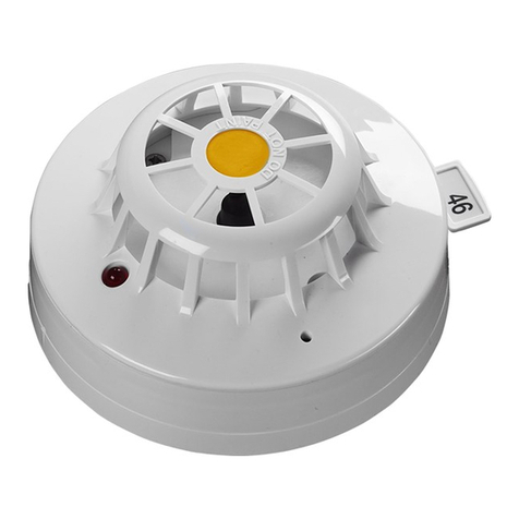
Telefire FireBeam Xtra Owner's manual

Input devices
FireBeam Xtra
Servo-Motorized Beam
Detector for Automatic
Alignment & Displacement
Compensation
Technical instructions
TELEFIRE FIRE AND GAS DETECTORS
LTD.
P.O. Box 7036
Petach Tikwa 49250
Tel: (03) 970 0400
Fax: (03) 921 1816
www.telefire.com
Date: 2.2020Revision: 1.11

i
Please Note!
Do not install, operate or conduct maintenance operations in the device before reading
this manual thoroughly.
©2007-2020 ALL RIGHTS RESERVED TO TELEFIRE FIRE AND GAS DETECTORS LTD.

70 -TBD
©2007-2020 ALL RIGHTS RESERVED TO TELEFIRE FIRE AND GAS DETECTORS LTD.REVISION 1.11 FEBRUARY 2020
Page 1of 19
1 Operation range and location
1.1 Operation range
FIREBEAM Xtra detectors can be installed at three distance ranges:
•7-70-m (detector + prims)
•70-140m (Detector + 4 prisms)
•140-160-m (detector + 9 prisms)

70 -TBD
©2007-2020 ALL RIGHTS RESERVED TO TELEFIRE FIRE AND GAS DETECTORS LTD.REVISION 1.11 FEBRUARY 2020
Page 2of 19
1.2 Location
When installed beneath a flat ceiling (where the level of the high part of the ceiling is not
60-cm higher than its lower part), the FireBeam detector can be installed at a level of 30-
60cm below the highest point on the ceiling, at a level up to up to 40-m from the floor.
The detection area is up to 7.5-m on both sides of the beam.
If the ceiling is sloped, install the detector 30-60cm beneath the highest point on the
ceiling. The beam width will be extended by 1% for each degree of ceiling slope.
Install the detector on a solid and stable structure.
Install the detector at a level of 2.7-m minimum from the floor, to prevent the passage of
people and equipment through the beam.
Also take into account the traffic of vehicles (forklift trucks) through the beam, as
relevant.
The detector location and installation distances will comply with these technical
instructions or Israeli Standard IS 1220, part 3, the stricter of the two.
!
Warning
Prevent solar radiation from directly entering the detector.
2 Installation
2.1 Installation of the detector head
Determine the location of detector installation. It is important to install it on a stable wall
at a level of 30-60-cm beneath the ceiling and at a distance of 50-cm minimum from an
adjacent wall.
Ensure a direct line of sight between the detector and point where the prism that refracts
the beam is installed.

70 -TBD
©2007-2020 ALL RIGHTS RESERVED TO TELEFIRE FIRE AND GAS DETECTORS LTD.REVISION 1.11 FEBRUARY 2020
Page 3of 19
Connect the detector head to its base by connecting the connector and tightening it to
the base with the Allen key supplied with the detector.
2.2 Installation of the control unit
Install the control unit at a suitable level, taking into account accessibility and
convenience considerations.
Insert the control unit through the screws holes outside the rubber seat. Wire to the
detector using the color connector.

70 -TBD
©2007-2020 ALL RIGHTS RESERVED TO TELEFIRE FIRE AND GAS DETECTORS LTD.REVISION 1.11 FEBRUARY 2020
Page 4of 19
2.3 Wiring

70 -TBD
©2007-2020 ALL RIGHTS RESERVED TO TELEFIRE FIRE AND GAS DETECTORS LTD.REVISION 1.11 FEBRUARY 2020
Page 5of 19
2.4 Alignment
Detector initialization.
The Firebeam detector initialization is an easy process.
Check that the installation is properly completed, according to the installation
instructions, and that the path of the laser beam to the reflector is free from
interferences.
The first stage is setting the language and the speed mode.
1. Important: the cover has to be removed from the reflector. The beam cannot be
started when the reflector is exposed.
2. Switch on the detector. FirebeamXtra will appear on the screen. The displayed
screen will be as follows:
3. Entre the menu by pressing Enter " "
4. The first screen you will see will be "English" . If you wish to
change language, use the right and left buttons to select the desired language.
When you finish selecting the desired language, press Enter.
5. Press Enter. The Normal Fast screen will be displayed. In most cases, it is
recommended to use Fast Mode (in Normal Mode, the system uses 3.5 mA and
in Fast Mode, it uses 17 mA). If you have no current limitations, it is preferable to
use Fast Mode to shorten the process. Fast Mode is 4 times quicker than Normal
Mode.
Use the right and left buttons to select between normal and fast mode. The *
(asterisk) indicates the selected mode. Press Enter to continue.
Beam alignment
6. The next screen is the Pre-alignment screen, the most important part in the
configuration of the beam detector settings.
The beam alignment defines the received signal strength for the distance
covered by the device, and provides a warning in case of reflections from
undesired sources.
7. Press Enter to start the beam alignment, as stated, with no reflector.

70 -TBD
©2007-2020 ALL RIGHTS RESERVED TO TELEFIRE FIRE AND GAS DETECTORS LTD.REVISION 1.11 FEBRUARY 2020
Page 6of 19
The receiver sensitivity adjustment starts by going up to 100%, and then the
output power is increased to 100%. Additional output power is provided if
necessary to cover the distance, and the said levels are reduced when an
automatic alignment process takes place. The air quality at this point has to
remain at 0%.
8. Press Enter to confirm the beam pre-alignment and settings, press the right
button and enter a manual alignment mode.
The Firebeam detector searches for the far wall of the building. In case of
installations with short distances, FireBeam will stop raising the infrared beam
intensity. In such cases, you can press Enter to confirm the alignment, and then
press the right button and Enter to enter a manual adjustment mode.
Caution: If a free radius of 50-cm is impossible, and the detector beam is
obstructed by objects, the IR intensity will stop increasing and the beam
alignment will be stopped when the beam conducts a wrong calculation, as in the
case of striking the far wall. In this case, the obstacle has to be removed or the
detector location/alignment have to be adjusted. The following figure presents an
example for an obstacle in the beam path.
Obstacles next to the upper part of the beam will interfere with the alignment
process, therefore you must make sure there is no solid object close to the beam
path.
Ensure a free range along the beam of 1.50-m from the reflector ends.
If the wall on which the reflector is placed is shiny or made of glass, a surface in
the size of 1-m. made of a non-reflecting material like MDF, has to be installed on
it to allow correct operation.
Manual alignment
At the completion of pre-alignment of the beam, enter a manual alignment mode.

70 -TBD
©2007-2020 ALL RIGHTS RESERVED TO TELEFIRE FIRE AND GAS DETECTORS LTD.REVISION 1.11 FEBRUARY 2020
Page 7of 19
9. Now locate or expose the reflector.
When you install or expose the reflector, the AQ value will increase to 135%.
This means that the beam detects the reflector. Press Enter to go to Auto
Alignment.
As long as there is a signal in the range of 80-100%, as the ideal value is above
100%, you can go to the next stage –auto alignment.
If the AQ does not significantly increase, use the left, right, up and down buttons
to move the detector eyes to the reflector. When properly placed, the AQ will be
significantly higher.
The detector can move by maximum 5 degrees by using the various direction
arrows. To make sure that the detector detects the reflector, cover the reflector.
The AQ will be significantly reduced.
Auto alignment
10. When the value of AQ is higher than 100%, manually press Enter to exit manual
mode and then press Enter to enter Auto Alignment mode.
Auto alignment is an automatic process that first reduces the sensitivity and
beam intensity, in order to achieve optimal settings, by the installation
environment.
The detector is automatically aligned to the center of the reflector. You can see
that axes X and Y move when the detector moves up, down, left and right.
When the detector finishes the process, Align Complete will be displayed. Press
Enter to confirm. The message Air Quality 100% Status –Normal will be
displayed.
Caution: This process can take 10 minutes. If the detector does not complete the
process after 10 minutes, check axes X and Y and make sure that the beam is
directed to the reflector and that there is no obstacle in the beam path.
Axes X and Y have to be below 1.5 each, and below 0.9 in normal state.
If this is not the case, start manual alignment and return the axes to 0.00 (Reset)
and remove any interfering object.

70 -TBD
©2007-2020 ALL RIGHTS RESERVED TO TELEFIRE FIRE AND GAS DETECTORS LTD.REVISION 1.11 FEBRUARY 2020
Page 8of 19
2.5 Inspection
Two tests have to be carried out to ensure the correct detector alignment:
"FIRE"TEST
Alarm - Cover the detector gradually and make sure that
the air quality is up to 70%. Cover the reflector with a
piece of cardboard. After 10 seconds the detector should
activate a fire alarm and a red LED will be lit.
PRISM INSPECTION TO ENSURE THAT THE BEAM IS
REFLECTED TO THE DETECTOR
Cover the prims entirely and quickly. If the beam is well
aligned, an error message will be displayed after 10
seconds. The yellow fault lamp on the detector head and
on the control unit will be flashing and the word FAULT
will be displayed.
3 Screens and menus
This screen is displayed when the beam is aligned.
The air quality is below the alarm threshold.
If the detector is set to latching alarm, you have to reset the
detector's alarm mode by Alarm Reset.
Reset can be conducted also by cutting off the power for 5
seconds. If automatic initialization was set, the detector will
initialize to normal mode automatically.
The beam path is completely blocked within 1 second (when
used to check for faults).

70 -TBD
©2007-2020 ALL RIGHTS RESERVED TO TELEFIRE FIRE AND GAS DETECTORS LTD.REVISION 1.11 FEBRUARY 2020
Page 9of 19
No communication with the controller. Check the wires. You can
check this by reading the resistance on the grey and black
terminals. If connected, 110-Ohm has to be shown, and if
disconnected, the resistance will be 220-Ohm.
This screen is displayed when the beam conducts alignment
(deviation compensation) due to displacements of the structure.
This screen is displayed when the detector reaches the end of the
compensation range. The fault or alarm lamps may be flashing.

70 -TBD
©2007-2020 ALL RIGHTS RESERVED TO TELEFIRE FIRE AND GAS DETECTORS LTD.REVISION 1.11 FEBRUARY 2020
Page 10 of 19
Specification of the main menus
Press Enter to enter the system menu. Then press Down to browse the main menu
options:
Press Enter to change the language.
Press Enter to align the detector.
Press Enter to set the detector settings (sensitivity, hysteresis,
etc.)
Press Enter for routine maintenance
Press Enter to access the settings of the transmission output,
receiver sensitivity, temperature and gain.

70 -TBD
©2007-2020 ALL RIGHTS RESERVED TO TELEFIRE FIRE AND GAS DETECTORS LTD.REVISION 1.11 FEBRUARY 2020
Page 11 of 19
Sub-menus The default language is English. If this is ok, press Enter to
continue the initiatlization. Press up to return to the home
screen. To change the language, press the left and right
arrows, and to confirm the language, press Enter. The
available languages are Enlish, Dutch, Italian, Spanich, Czech
and German.
Press Enter to enter the commissioning screen.
Press the right and left buttons to change between normal and
fast mode. In most cases, it is recommended to use fast mode
(in normal state, the system uses 3.5mA and in fast mode,
17mA).
Press Enter to start pre-alignment. When conducting pre-
alignment, the reflector must be always covered. Start with
receiver settings of 10% output and 5% sensitivity. The
receiver sensitivity will be automatically increased to 100%,
and then the output power will increase. These settings will be
automatically disabled when the received signal, with no
reflector, reaches 6%. If the detector increases gradually to
100%, the message "Pre Align Complete" will be displayed.
Otherwise, a too high output power was obtained, because of
reflection of light from an adjacent object.
Use the left, right up and down arrow keys to avoid the objects
that blocks the reflector.
When the readings are correct, press Enter and confirm by
pressing the right arrow key to enter manual alignment. If you
wish to abort the pre-align command, press the left arrow key.
Press Enter to enter manual alignment. Now the reflector has
to be installed and exposed. A high jump in the signal intensity
should be observed. If not, use the X and Y buttons to
properly align the reflector (the higher the signal intensity, the
more aligned the beam). Try to reach 100% or more for auto
alignment. Press Enter to confirm and enter Auto Alignment.
Press Enter to start Auto Alignment. The beam will calibrate
the power and search for the reflector ends –it will adjust the
power when aligned with the reflector. When the four reflector
ends are detected twice, the detector will be aligned to the
center and Align Complete will be displayed. Press Enter to
return to the main menu, if Align Aborted is displayed, this
means that an object obstructs the received signal beam.
Press Back or the left arrow to return to Auto Alignment.

70 -TBD
©2007-2020 ALL RIGHTS RESERVED TO TELEFIRE FIRE AND GAS DETECTORS LTD.REVISION 1.11 FEBRUARY 2020
Page 12 of 19
Here you can change the beam behavior. Press Enter to enter
the mode change menu and sub-menus.
Press the left and right arrow keys to increase/decrease the
beam sensitivity. The default is 35% (meaning the received
signal has to decrease by 35% to activate the alarm relay. This
sensitivity can range between 25-50%). Press Enter to return
to Mode Change or the down arrow to enter Time to Fire.
Here you can set how much time the beam has to be in Time
to Fire state before it activates the alarm relay. As default, this
time is set to 10 seconds. You should increase this time if
there are interferences like birds, lifting platforms etc. This time
can be set between 2-30 seconds, by pressing the left and
right arrows (press Enter to return to Mode Change or the
down arrow to Time to Fault.
Here you can set the fault time between 2-60 seconds by
pressing the right and left arrows (the default is 10 seconds).
In order for the beam to enter fault mode, the beam has to be
completely blocked within 1 second (press Enter to return to
Mode Change or the down arrow for Auto Reset.
The detector's default is Auto Reset, when the received signal
exceeds the alarm threshold. The detector can be set to
latching alarm, by the right and left arrows. Press Enter to
return to Mode Change or to down arrow to enter Auto Reset.
Align On/Off allows to cancel the auto alignment function for
compensation. For example, in an environment where there is
a lot of smoke from welding, Auto Alignment will be on when
the received signal is less than 90%, the value at which the
beam automatically checks for structure displacements. The
beam will try to align through the smoke, which can be difficult
if the beam does not detect the reflector edges. Use the right
and left arrows to switch it on and off. When this function is
disabled, check that the detector is installed on a rigid surface,
free from movements. Auto Alignment will still be enabled in
commissioning state (press Enter to return to Mode Change
or the down arrow to go to Align Time.
The default is 4 hours. It can be changed, using the left and
right arrows, between 0 and 12 hours.

70 -TBD
©2007-2020 ALL RIGHTS RESERVED TO TELEFIRE FIRE AND GAS DETECTORS LTD.REVISION 1.11 FEBRUARY 2020
Page 13 of 19
Use the right and left arrows to turn on or off the green
flashing LED lamp on the controller.
When using several beam detectors directed one against the
other, an error in data reading can occur. By properly setting
each beam and its phase, you can solve this problem. Use the
right and left arrows to set a different phase pattern for each
beam (conduct samplings of the output beam). You can
choose from 0 (default) to 6 (press Enter to return to Mode
Change or the down arrow to go to Hysteresis.
A change in the hysteresis changes the hysteresis in the
transition between Fire mode back to Normal Mode. For
example, the beam default is 15%, such that if the beam is set
to alarm mode at 65% (threshold of 35%), the beam intensity
has to reach 15-80% before it returns to normal state. This
operation prevents fluctuations in the reflected signal causing
the beam to go in and out of alarm mode. It can be adjusted
between 1% and 40% using the left and right arrows (press
Enter to return to Mode Change or down to go to
Compensation fire/ fault).
Press Enter to go to Beam Maintenance.
This screen displays the beam compensation due to
construction dust that goes up to the beam head and reflector.
Always look at this value as part of the ongoing maintenance.
If a value higher than 50% is displayed, the beam head and
reflector have to be cleaned (after cleaning, activate auto
alignment to reset the beam).
A negative value can be displayed, when the detector is
installed in a dusty environment. To reset, press Auto
alignment (press Enter to return to Beam Maintenance or
the down arrow to go to Event Counts).

70 -TBD
©2007-2020 ALL RIGHTS RESERVED TO TELEFIRE FIRE AND GAS DETECTORS LTD.REVISION 1.11 FEBRUARY 2020
Page 14 of 19
You can see the number of times the beams was in fault or
alarm mode since the detector was installed or since the
recent event list was erased, including tests.
Press Enter to clear events.
Press the left/right arrows to go to Beam Maintenance or
the down arrow to go to self-test.
Press Enter to conduct self-test. In this screen, an
algorithm test is run to reduce the input power. The
receiver identifies this as blocking, when the received
signal is below a threshold value. The beam activates the
alarm relay. The relay will not be released before the Time
to Fire expires. This value can be between 2-30 seconds.
Press the left/back arrows to end the test. Fire Test will be
displayed. Press the left/back arrows to return to Beam
Maintenance or down to go to On/Off.
If a maintenance operation has to be done on the beam
path, use the right and left arrows to switch the system on
or off. This will appear as a fault.
Press Enter to go to Beam maintenance.
Press Enter to go to the Diagnostics screen.
This screen presents the level of transmitted output power.
This value can be increased or decreased by using the left
and right arrows (press Enter to return to Diagnostics or
down to go to RX Sensitivity).
This screen presents the temperature of the detector head
and the necessary temperature adjustment. Press Enter to
return to Diagnostics.

70 -TBD
©2007-2020 ALL RIGHTS RESERVED TO TELEFIRE FIRE AND GAS DETECTORS LTD.REVISION 1.11 FEBRUARY 2020
Page 15 of 19

70 -TBD
©2007-2020 ALL RIGHTS RESERVED TO TELEFIRE FIRE AND GAS DETECTORS LTD.REVISION 1.11 FEBRUARY 2020
Page 16 of 19
4 Connection to the TeleFire panels
i
Note
24VDC supply to the detector will be provided from 24R input in TSA-200 /
TSA-240 and TSA-1000 panels, and from 24V input for ADR-712 assembly.
Make sure that the ADR-712 assembly is of software version 6 and higher.
Do not use ADR-812A assembly to connect to addressable panels .
Usually smoke that goes up starts spreading sideways at a certain distance below the
ceiling, because of a layer of hot air that is found next to the ceiling. Therefore the
detector has to be installed on the building wall, at least 50-cm and no more than 1-m
below the ceiling, to meet the requirements of NFPA 72/ UL 268 and Israeli Standard IS
1220-3, 2014 revision.
4.1 Connection to addressable panels
Drawing 1: Connection of FireBeam detector to addressable panels
Note!
In software version 6 and higher of the
ADR-712, TBR-5100 reset circuit is not
necessary. Do not use assemblies of
software revision 5 and lower.
Zone 2
Zone 1
24V supply to zones
24VR supply
Fire beam detector
Continued 24V line to the next device
Communication line to the next device
Communication line to devices
from the panel or previous
device
Connect 5.1k end-of-line resistor to
each zone
Continued 24V line to the next device
Shielding

70 -TBD
©2007-2020 ALL RIGHTS RESERVED TO TELEFIRE FIRE AND GAS DETECTORS LTD.REVISION 1.11 FEBRUARY 2020
Page 17 of 19
4.2 Connection to TSA-1000 panel
Drawing 2: Connection of Fire Beam detector to TSA-1000 panel
Note!
When connecting a beam detector to TSA-
1000 panel, properly set the zone to verify
the alarm.
FireBeam detector

70 -TBD
©2007-2020 ALL RIGHTS RESERVED TO TELEFIRE FIRE AND GAS DETECTORS LTD.REVISION 1.11 FEBRUARY 2020
Page 18 of 19
4.3 Connection to TSA-200 / TSA-240 panel
Drawing 3: Connection of Fire Beam detector to TSA-200 / TSA-240 panel
Note!
When connecting a beam detector to TSA-
200 panel, properly set the zone to verify
the alarm.
FireBeam detector
Table of contents
Other Telefire Security Sensor manuals
