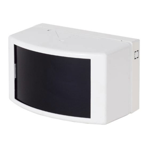
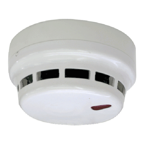
Telefire TFB-180SA Owner's manual

אצומ ינקתה
TFB-180SA / TFB-180BSA
Detector base integrated with a
addressable horn/strobe horn
Technical instructions
TELEFIRE GAS AND FIRE DETECTORS
LTD.
P.O. Box 7036
Petach Tikwa 49250
Tel: (03) 970 0400
Fax: (03) 921 1816
www.telefire.com
TFB-180BSAHb101.pdf
Date 4.2.2020
Rev 11.0

i
Note
The equipment must not be installed, operated or maintained before reading this
manual and understanding its content.
2020 – 2019 ALL RIGHTS RESERVED TO TELEFIRE GAS AND FIRE DETECTORS LTD.

2019 – 2020 © ALL RIGHTS RESERVED TO TELEFIRE GAS AND FIRE DETECTORS LTD. Rev 1.01 Date 4.2.2020
Page 1 of 7
1 Introduction
TFB-180SA and TFB-180BSA are devices with a base for an addressable detector integrated
with an addressable horn or a base for an addressable detector integrated with an addressable
strobe horn.
There are two models:
•TFB-180SA –base for an addressable detector integrated with an addressable horn
•TFB-180BSA –base for addressable detector integrated with an addressable strobe horn
The bases comply with the Telefire addressable detector series (TFO-480A ,TFH-280A ,
and TPH-482A).
Pressing the Horn Silence button in the fire detection panel stops the operation of the horn and
strobe light.
2 Compatibility
2.1 Fire detection panels
The addressable strobe horn and horn comply with the following panels:
•ADR-7000 ,SAVER-7000 ו , - GUARD-7
•ADR-3000 ו- ADR-SAVER
2.2 Detectors
The addressable strobe horn and horn serve as a basis for the following detectors:
•TFO-480A
•TFH-280A
•TPH-482A
3 Installation
The quantities and location of detectors and alarm devices will be planned according to the
latest Israeli standard IS 1220, part 3, and upon the requirements of the planning consultant.
3.1 Planning of the installation
3.1.1 Capacity Planning
Make sure the fire detection panel has free addresses, as necessary.
3.1.2 Wiring planning –communication line to addressable devices
Use a 2-strand wire of 12-20AWG (section area –quadrat –of 0.5-3.3mm2). The
following table presents the maximum line lengths by the section area of each cable
strand. It is recommended to use a twisted pair when the detection loop connects
between different buildings.
Cable type
Maximum cable length (for a given size) as input
to:
Cable
(AWG)
Diameter
(mm)
Section
(mm2)
ADR-7000 ,SAVER-7000 ,GUARD-7 ו ,- ADR-3000
20
0.812
0.518
570

2019 – 2020 © ALL RIGHTS RESERVED TO TELEFIRE GAS AND FIRE DETECTORS LTD. Rev 1.01 Date 4.2.2020
Page 2 of 7
Cable type
Maximum cable length (for a given size) as input
to:
Cable
(AWG)
Diameter
(mm)
Section
(mm2)
ADR-7000 ,SAVER-7000 ,GUARD-7 ו ,- ADR-3000
19
0.912
0.653
710
18
1.024
0.823
900
17
1.15
1.04
1,125
16
1.291
1.31
1,425
15
1.45
1.65
1,800
14
1.628
2.08
2,275
13
1.828
2.62
2,875
12
2.053
3.31
3,625
Table 1: selection of communication loop cables for addressable devices (SLC)
i
Note
IS 1220 part 3 (2014) states in section 12.1.4 that "When using cables that
are composed of two strands and up, the section area of each conductor in
the cable strand will be 0.5 mm2, as a minimum".
The cable lengths stated in table 1 are brought as an estimate, assuming the
cables are single-stranded.
In any case, the cable resistance, as measured in the field, has to be taken
into account.
In communication lines for addressable devices (SLC), the loop resistance
and capacitance –the stricter of the two, has to be considered. The
capacitance of the SLC loop will not exceed 1 μF .
3.1.3 Wiring planning –24VDC supply
The assembly is fed by +24Vdc supply from the panel or local addressable power
supply, like TPS-74A or TPS-34A.The resistance of the power supply line between the
power source 24Vdc and an addressable assembly will be calculated such that the
maximum voltage drop at the end of line, under full load, will not exceed 2V, or a
voltage level that supplies the last device with the minimum operating voltage,
according to the manufacturer's data –the stricter of the two.
Use TPS-74A or TPS-34A when the assembly is installed far from the panel, or when
the sum of consumer currents in regular operating mode or in alarm state exceeds the
maximum permissible current on the main power supply (the panel).

2019 – 2020 © ALL RIGHTS RESERVED TO TELEFIRE GAS AND FIRE DETECTORS LTD. Rev 1.01 Date 4.2.2020
Page 3 of 7
i
Note
24V lines that feed several loops will be split only on the panel output. It is
forbidden to connect in the field 24V lines to different loops.
TPS-74A or TPS-34A power supply will feed 24V to devices that belong to
one loop only. It is forbidden to bridge 24V between devices in the field that
belong to different loops.
3.1.4 Wiring planning –shielding
It is recommended not to conduct wiring outside of a building, because of the potential
risk of lightning strike. If necessary, shielded cables must be used. The shield must be
connected to the grounding by the grounding clamps on the panel.
3.1.5 Location
The device has to be installed indoors. Exposure to outdoor and weather conditions
must be prevented to avoid high humidity or dust and air contamination from external
sources.
3.1.6 Connection of 24V power input and communication line to addressable
devices
Connect to the assembly the communication line for addressable devices (SLC) from
the panel, and 24VDC input from the panel or external power source, like TPS-74A or
TPS-34A .
i
Note
Check the wiring before making the connection, to ensure that is no short-
circuit in the wires.
The addition or removal of assemblies from the panel will be done when the
power sources to the panel (AC input voltage and batteries) are
disconnected.
Drawing 1: wiring of TFB-180BSA or TFB-180SA
To the next device
From the panel or
previous device

2019 – 2020 © ALL RIGHTS RESERVED TO TELEFIRE GAS AND FIRE DETECTORS LTD. Rev 1.01 Date 4.2.2020
Page 4 of 7
3.2 Installation
3.2.1 Programming of the device address
Burn the address of the horn/strobe horn to the device's card. Use the wire supplied with
the software PROG-4000 or the technician kit TFC-7000 and connect the gator clips to
lug 1 (positive) and 2 (negative).
i
Note
Burning an address to the base sets the address of the horn/strobe horn only.
The detector installed on the base uses its own address and the setting of the
device on the panel.
3.2.2 Device settings on the panel
Set the assembly on the panel to "Silenced Horn". When this option is selected, the horn
will be off.
On the TFB-180BSA, setting the panel to Silenced Horns will disable the horn, but the
strobe light will continue to be on, until Respond is pressed in the panel.
Set the operating matrix of the device in the panel. Read the technical instructions of the
panel for additional instructions about setting the devices and operating matrix.
3.2.3 Configuration switches – TFB-180BA
i
Note
The switch is set to 1 when the selector is close to 1, and to 0 when the
switch is away from 1 (OPEN state).
Switch
3
Switch
2
Switch
3
Sound
1
1
1
Constant - 910Hz
1
1
0
Goes up from 500Hz to 1,200Hz for 3.5 sec; stops for
0.5 seconds
1
0
1
Switches between 910Hz and 685Hz at a rate of 2Hz
1
0
0
Intermittent sound, half a second at 910Hz, half a
second off
0
1
1
Goes down from 1,200Hz to 500Hz every second
0
1
0
Sounds three pulses of 500mS at 910Hz and then
goes off for 1.5 seconds
0
0
1
Goes up and down every 0.5 second in the range of
800Hz –1,000Hz
0
0
0
Goes up from 800Hz to 970Hz every second

2019 – 2020 © ALL RIGHTS RESERVED TO TELEFIRE GAS AND FIRE DETECTORS LTD. Rev 1.01 Date 4.2.2020
Page 5 of 7
3.2.4 Configuration switches – TFB-180BSA
i
Note
The switch is off when the selector is close to the digit, and on when the
switch is far away from the digit.

2019 – 2020 © ALL RIGHTS RESERVED TO TELEFIRE GAS AND FIRE DETECTORS LTD. Rev 1.01 Date 4.2.2020
Page 6 of 7
- Switch 1: sets the operating mode to horn/strobe or horn only.
- Switch 2: volume adjustment: high volume (off) or low volume (On).
- Switches 3 and 4: the horn sound:
oContinuous sound (910Gz): switch 3 is On, switch 4 is On
oBell (1440 Hz), switch 3 is On; switch 4 is Off
oAlternating sound (910Hz/600 Hz), switch 3 is Off; switch 4 is On.
- Switch 5: stay in off state.
3.2.5 Device connection
Connect the device to the communication line of addressable devices and +24Vdc input.
i
Note
Measure the wiring to ensure there is no short circuit or connection or
leakage to the ground, before connecting the device to the fire detection
panel.
Addition or connection of devices to the fire detection panel will be done
when all power sources to the operation panel (AC input voltage and
batteries) are disconnected.
Notify the system manager that the fire detection panel will be temporary cut
off, before adding devices to the panel.
3.3 Preinstallation tests
Check that the device is included in the relevant matrix and follow the provisions of the
standard and the instructions of the planning consultant.

2019 – 2020 © ALL RIGHTS RESERVED TO TELEFIRE GAS AND FIRE DETECTORS LTD. Rev 1.01 Date 4.2.2020
Page 7 of 7
4 Technical data
Diameter ( including base)...................................... 124 mm
Height (without detector)......................................... 58 mm
Operation temperature range: ................................ -10°C –+60°C
Relative humidity: ................................................... 10% –93% without condensate
Operating voltage
(supplied by the operation panel on the device communication line) 20V modulated
(supplied by the operation panel or addressable output assembly) 24 Vdc
4.1 TFB-180SA
Maximum current consumption –device line .......... 180 µA (quiescent state)
2 mA (alarm state)
Maximum current consumption from 24Vdc power source 10 mA (quiescent state)
22 mA (alarm state)
4.2 TFB-180BSA
Maximum current consumption –device line .......... 180 µA (quiescent state)
2 mA (alarm state)
Maximum current consumption from 24Vdc power source 12 mA (quiescent state)
34 mA (alarm state)
All data are nominal and can be changed without prior notice.
5 Accreditation
The equipment meets the following standards:
•Certified to Israeli standard IS 1220
This manual suits for next models
1
Table of contents
Other Telefire Security Sensor manuals
Popular Security Sensor manuals by other brands
GROUNDTECH
GROUNDTECH DISCOVERY Series user manual
Code 3
Code 3 Sprinter Installation & operation manual

Hytronik
Hytronik HIM38/RF Installation and instruction manual
Argus Security
Argus Security TAURUS TW-DO-01 quick start guide
Theben
Theben PlanoCentro 101-E Series operating manual
Inficon
Inficon Sensistor XRS9012 user manual
