Telefire TFO-480A User manual
Initiating Devices
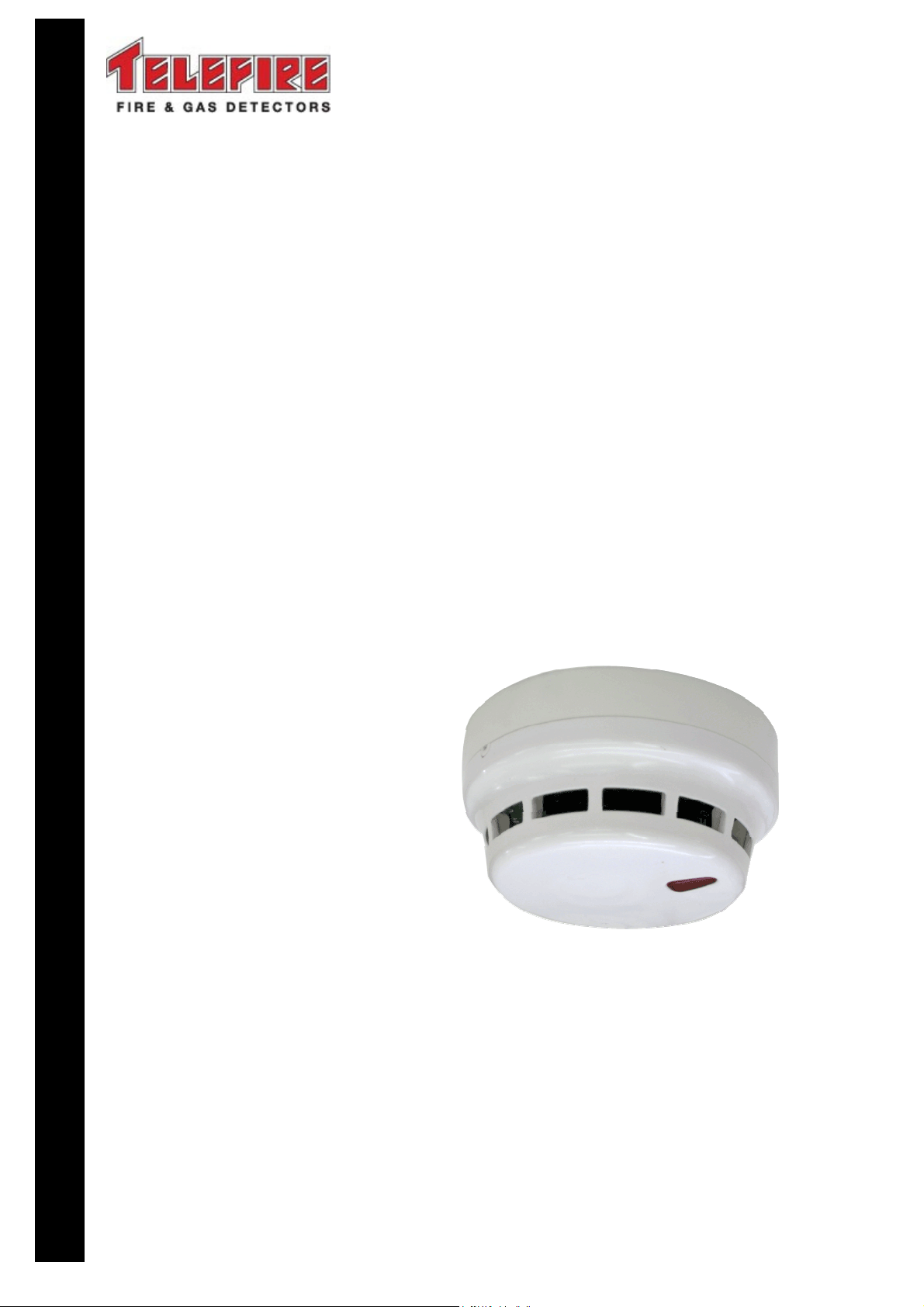
TFO-480A
Analog Addressable
Photoelectric Smoke Detector
Technical Manual
T
ELEFIRE
F
IRE
&
G
AS
D
ETECTORS
L
TD
PO Box 7036
Petach Tikva 49250
Israel
Tel: 972 3 921 1955
Fax: 972 3 921 1816
eMail: marketing@telefire.co.il
Web: www.telefire.co.il
TFO
TFOTFO
TFO-
--
-480A
480A480A
480AEn
EnEn
En101
101101
101.pdf
.pdf.pdf
.pdf
Revision 1.01
January 2012

i Note
The terms “Trouble” as used in NFPA 72 guideline, UL 864 and UL 268
standards and “Fault” as used in EN 54 standards are used interchangeably
throughout this manual.
i Note
Do not install, operate, and maintain this product before fully reading this
manual.
© 2010 – 2012 Telefire Fire & Gas Detectors Ltd.

TFO-480A
© 2010 – 2012 Telefire Fire & Gas Detectors Ltd Revision 1.01 January 2012
– Page 1 of 5 –
1 Introduction
Telefire's TFO-480A Analog Addressable Photoelectric Smoke Detector is an advanced
detector that offers the following advantages:
•It is considered “green” (environment friendly) as it does not contain radioactive
materials.
•The TFO-480A contains a powerful microprocessor that performs initial signal
processing locally. The final processing and decision making is performed by the
control panel.
•The TFO-480A's microprocessor offers a high level of noise immunity and
interactively performs with the control panel drift compensation in order to overcome
environmental changes and dust accumulation in the chamber. Once the detector is
no longer able to compensate the control panel will display a trouble signal
requesting cleaning. The microprocessor also performs signal processing, enables
accurate control of the photoelectric chamber according to parameters set at the
control panel, and manages the communication process with the control panel.
•The TFO-480A detector excels in sensing smoldering smoke and smoke from
burning of various materials.
•Soft-set address – the detector’s address is programmed into its memory without
the use of mechanical switches or moving parts.
•Can be tested directly with a test magnet or remotely from the control panel.
•The detectors chamber and labyrinth can be cleaned in the field by authorized
people.
The detector consists of a vented chamber (labyrinth), an infrared transmitter and a
receiver that detects light scattering from the smoke particles in the chamber.
The sensitivity of the detector can be adjusted from the control panel within the range of
0.8% – 2.0%/foot (obscuration) in 0.2% increments. Please refer to the appropriate
control panel manual for details.
The detector contains an alarm LED that has 360°visibility. This LED flashes during
normal operation and is latched on during an alarm.
2 Compatibility
2.1 Control Panels
The TFO-480A is compatible with Telefire's ADR-3000 Analog Addressable Control
Panel.
2.2 Bases
The TFO-480A is compatible with Telefire's TFB-180 Standard Detector Base.
!
Warning
Do not connect these detectors to control panels made by
manufacturers other than Telefire.
3 Installation
Planning of quantity and location of detectors shall be done according to the local codes
and regulations and in accordance to the planning consultant's requirements.

TFO-480A
© 2010 – 2012 Telefire Fire & Gas Detectors Ltd Revision 1.01 January 2012
– Page 2 of 5 –
3.1 Pre-Installation Planning
3.1.1 Capacity Planning
Ensure that the total number of initiating devices (detectors, switches, call point, etc.)
does not exceed the maximum allowed per detection zone, floor area, or other
limitations as specified by the applicable standards and regulations. Ensure that the
ADR-3000 has an available address for each detector.
3.1.2 Cabling Planning
The detector is connected to the control panel via a TFB-180 standard detector base via
a two-wire connection (the control panel's SLC loop). The detector has an output for
activating a TFL-1AN Auxiliary Signaling Indicator for Analog Addressable Detectors. It
is recommended that you use a twisted pair cable for SLC connection. Please look at
the technical manuals of the TFB-180 and TFL-1AN for additional details about
connecting the SLC cables and TFL-1AN to the base.
i
Note
Notify the operator or the security personnel that the system will be temporary
disconnected before adding detectors to the control panel.
3.2 Installation
3.2.1 Address Programming
Assign the TFO-480A’s address in the range of 1 – 127 prior to installation by using the
PROG-4000 Analog Addressable Detector and Accessory Programmer. Please refer to
the PROG-4000 manual for additional details.
3.2.2 ADR-3000 Configuration
Configure the detector as “Photoelectric Detector” in the ADR-3000. Configure the
detector’s sensitivity at the control panel (“0.8” – most sensitive, “2.0” – least sensitive”) ,
if required.
Please refer to the ADR-3000 technical manual for a detailed description of
programming and configuration.
3.2.3 Location
The TFO-480A is designed to protect indoor fire risk areas, except environments where
smoke, steam, dust, or corrosive gasses are present under normal conditions.
Photoelectric smoke detectors should be used for detecting smoldering fires in corridors
and along escape routes, wood- or paper stores, electric cabinets, etc., They should not
be used in steamy, dusty, or smoky areas such as kitchens, bathrooms, saunas,
laundries, etc.
Observe NFPA 72 guidelines and local fire codes when installing the TFO-480A.
When installing a TFO-480A smoke detector on a slanted (up to 45°) ceiling that allows
free flow of smoke (i.e., there are no beams or other obstacles) the detector should be
installed parallel to the flow line of the ceiling, and not horizontally. For ceilings with
impediments to free smoke flow please refer to the relevant local fire code standard.
Use only Telefire's TFB-180 Standard Detector Base.
For remote signaling use only Telefire's TFL-1NA Auxiliary Signaling Indicator for Analog
Addressable Detectors.

TFO-480A
© 2010 – 2012 Telefire Fire & Gas Detectors Ltd Revision 1.01 January 2012
– Page 3 of 5 –
UL
UL Requirement
Smoke detectors are not to be used with detector guards unless the
combination has been evaluated and found suitable for that purpose.
3.2.4 Connecting to the ADR-3000 SLC Line
Connect the SLC to the detector’s base. Refer to the TFB-180 technical manual for
wiring diagrams.
All wiring must conform to applicable local codes, ordinances and regulations.
i
Note
Measure the wiring to ensure there are no shorts before connecting the wiring
to the control panel.
Connecting or adding detectors to the control panel shall be done when all
power to the control power (AC and batteries) is disconnected.
3.2.5 Detectors Init
It is recommended that you perform detector initialization after initial system activation,
adding, or replacing detectors in order to reduce system stabilization time. If you do not
perform this action, it will be done automatically within several hours of normal operation.
Please see the control panel's technical manual for an explanation on performing
Detectors Init.
i
Note
Ensure that detector initialization is performed when all detectors are in a
smoke-free condition.
3.3 Post-Installation – Field Test
Perform a field test (also known as "Walk Test") to ensure that all detectors function
properly. Please see the control panel's manual for a detailed explanation on how to
perform a field test.
Testing is automatic other than the activation of the detector that is done manually by
putting a magnet next to the detector's test point. See section 4.1.1 for a detailed
explanation on how to perform the test.
Ensure that the detector functions properly and is included in the necessary activation
matrices.
!
Warning
Do not apply naked flame to the detector!
3.4 Documentation
Mark the detector's address on the label.
4 Maintenance
The ADR-3000 control panel monitors the analog detectors continuously. Any abnormal
condition in the detector will cause a trouble signal to be displayed on the control panel.
When a detector becomes contaminated to a degree that cannot be compensated, the
control panel will display a maintenance trouble signal. At this point the detector must
be cleaned.
Table of contents


