TELEFLY TELE2210G-2GF-8GT User manual

TELE2210G-2GF-8GT
Full Gigabit Din-rail mount Industrial
Ethernet Switch
User Manual
(Edition: V1.0)
www.telefly.cn
TELEFLY TELECOMMUNICATIONS EQUIPMENT CO.,LTE

TELE2210G-2GF-8GT Full Gi
g
abit Din-rail mount Industrial Ethernet Switch
III
Safe Use Instruction
This product performance is excellent and reliable in the designed range of use,
but it’s necessary to avoid man-made damage or destroy for the
equipment.
Read the manual carefully and keep this manual for reference if need
afterwards.
Do not put the device close to the water sources or damp places.
Do not put anything on the power cable, it should be placed out of reach.
To avoid causing fire, do not knot or wrap the cable.
Power connector and other device connectors should be firmly
connected with each other, frequently inspection is needed.
Please keep the fiber socket and plug clean. Do not look directly at the
fiber section when the equipment is working.
Please keep the equipment clean and wipe it with a soft cotton cloth if
necessary.
Please do not repair the equipment by yourself, unless there is clear
instructions in the manual.
Under the following circumstances, please cut off power immediately and
contact us.
Equipment water damage.
The equipment is broken or the casing is broken.
The equipment works abnormally or the performance has completely
changed.
The equipment produces odor, smoke or noise.
Statement: Information requiring explanation in use of the managed software.
Attention: Matters requiring specific attention in the use of the managed
software.
www.telefly.cn

IV
Catalogue
1. System outline............................................................- 1 -
1.1. Product Introduction.................................................................... - 1 -
1.2. Product Characteristic................................................................ - 1 -
1.2.1. Industrial network features................................................................- 1 -
1.2.2. Industrial-grade power supply design............................................. - 1 -
1.2.3. Solid exterior design.......................................................................... - 1 -
1.3. List...................................................................................................- 2 -
1.4. Product election............................................................................- 2 -
2. Technical Index...........................................................- 3 -
3. Hardware installation and testing......................... - 4 -
3.1. Hardware structure...................................................................... - 4 -
3.1.1. Product configuration.........................................................................- 4 -
3.1.2. Front panel and side panel............................................................... - 4 -
3.2. Power supply................................................................................ - 5 -
3.2.1. LED indicator lights............................................................................ - 6 -
3.3. Hardware installation...................................................................- 6 -
3.3.1. Din-rail installation..............................................................................- 6 -
3.3.2. Cable connection............................................................................... - 7 -
3.3.3. Fiber connection.................................................................................- 7 -
3.4. Simple test.....................................................................................- 9 -
3.4.1. System self-examination...................................................................- 9 -
3.4.2. RJ45 port testing................................................................................ - 9 -
3.5. Fiber port testing.......................................................................... - 9 -
4. Maintain and service...............................................- 11 -
4.1. On-line service............................................................................- 11 -
4.2. Call for technical support service........................................... - 11 -
4.3. Warranty Policy.......................................................................... - 11 -
TELE2210G-2GF-8GT Full Gi
g
abit Din-rail mount Industrial Ethernet Switch
www.telefly.cn

- 1 -
1. System outline
1.1. Product Introduction
The TELE2210G-2GF-8GT is a high performance unmanaged industrial
Ethernet switch with total 10 Gigabit Ethernet ports. It has 2x1000Base-X SFP
fiber ports and 8x10/100/1000Base-T RJ45 ports, which is suitable for the big
bandwidth Ethernet communications.
The product has a power failure alarm output function which is helpful for
field engineers to discover and deal with faults in time. It adopts standard
35mm pitch DIN rail installation method and very suitable for industrial field
installation applications.
1.2. Product Characteristic
1.2.1. Industrial network features
Store-and-forward switch with 20G bandwidth
Support 2x1000Base-X SFP ports for fiber connection.
8x 10Base-T/100Base-TX/1000Base-T adaptive port, automatic
MDI/MDI-X connection.
According to the IEEE802.3, IEEE802.3u, IEEE802.3ab, IEEE802.3x
standard.
Stably work in strong electromagnetism environments.
1.2.2. Industrial-grade power supply design
Provide different power supply application options:
DC power supply range: DC12~48V(redundant dual power input
supported)
DC/AC power supply range: DC110~370V and AC85V~264V(only single
power input)
Reliable EMC protection and over-current/ over-voltage protection.
With relay alarm output function and can be connected to other sound
and light alarm equipment.
1.2.3. Solid exterior design
Single-ribbed aluminum chassis cooling surface design, efficient heat
dissipation without fan, the system can work reliably at -40 °C ~ +85 °C
environment.
Closed high-strength aluminum casing, enabling the system to work
reliably in harsh and hazardous industrial environments.
Standard DIN-Rail mounted installation and it is also ok to provide
accessories required for other installation methods.
TELE2210G-2GF-8GT Full Gi
g
abit Din-rail mount Industrial Ethernet Switch
www.telefly.cn
- 2 -
1.3. List
The product package of TELE2210G-2GF-8GT contains the following
items. If any of the items is lost or damaged, please contact the agent or the
customer service center of Co., Ltd., they will
assist you to replace or supplement.
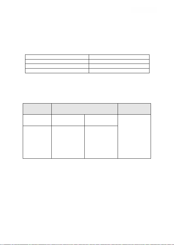
Chart 1-1 Industrial Ethernet Switch Product Packing List Table
Item Quantity
TELE2210G-2GF-8GT switch 1
User manual 1
Certificate and warranty card 1
1.4. Product election
The TELE2210G-2GF-8GT switch provides two types of AC and DC
products for customers to choose. The product model list is shown in Table 1-2.
Table 1-2 TELE2210G-2GF-8GT switch product model list
Optional
model Port Power supply
range
Standard
model Fiber port Copper port 1:DC power
supply 12~48V
2:AC power
supply:
DC110~370V
or
AC85~264V
adaptive
TELE2210G
-2GF-8GT 2 8
Telefly Communications Equipment
TELE2210G-2GF-8GT Full Gi
g
abit Din-rail mount Industrial Ethernet Switch
www.telefly.cn

- 3 -
2. Technical Index
Content TELE2210G-2GF-8GT
Ports quantity
2x1000Base-X SFP socket
8x10Base-T/100Base-TX/1000/Base-T RJ45
port
System parameter
Standard support: IEEE802.3,IEEE802.3u,
IEEE802.3ab,IEEE802.3x
MAC address table:4K
Switch method: storage and forward
Fiber port parameter
GF:1000Base-X
Wavelength: 1310nm or 1550nm (Single
mode); 850nm (Multimode)
Transmission Distance: 10~80Km optional
(Single mode) ;550m (Multi mode)
Converter type: shielded SFP socket
Transport rate: 1.25Gbps
RJ45 parameter
Physical port:RJ45 (shielded)
RJ-45 port:
10Base-T/100Base-TX/1000Base-T,auto-neg
otiation
Transmission distance:100m (standard
CAT5, CAT5e network cable)
Power parameter
Voltage input:
a.DC power:DC12~48V(redundant dual
power input supported)
b.DC/AC power:
DC110~370V/AC85V~264V(only single
power input)
Power consumption: 5.2@DC24V (full load)
Overcurrent protection: built-in
Mechanical parameter
Shell: Metal with no fan
Dimensions(HWD):138mm110mm54m
m(not include the DIN rail equipment
dimensions)
IP grade:IP40
Installation:din-rail mountin
g
Working environment
Working Temperature: -40℃~+85℃(AC
power supply model: -25℃~+70℃)
Storage temperature: -40℃~+85℃
Humidity: 5~95% (no condensation)
TELE2210G-2GF-8GT Full Gi
g
abit Din-rail mount Industrial Ethernet Switch
www.telefly.cn

- 4 -
3. Hardware installation and testing
3.1. Hardware structure
3.1.1. Product configuration
The TELE2210G-2GF-8GT uses Din rail mount installation and whole
machine with six sides fully enclosed structure.The dimensions(not including
DIN rail size) are: 136mm×54mm×110mm (height×width×depth).
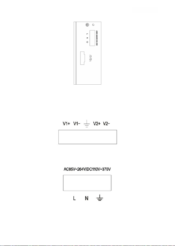
3.1.2. Front panel and side panel
Front panel
Side panel of DC12~24V model
TELE2210G-2GF-8GT Full Gi
g
abit Din-rail mount Industrial Ethernet Switch
www.telefly.cn
- 5 -
Side panel of DC/AC model
3.2. Power supply
The DC power supply model of the TELE2210G-2GF-8GT switch supports
DC12~48V power supply, dual power input, and the two power supplies are
mutually backup. Use 5-ways lockable 5.08mm pitch terminal, as shown in the
figure below:
The TELE2210G-2GF-8GT has a 3-ways lockable 5.08mm pitch terminal
and the DC/AC power model supports DC110~370V and AC85~264V power
supply,as shown in the figure below:
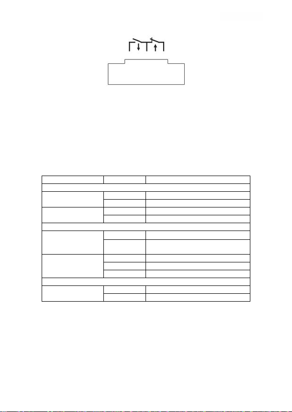
Power failure alarm relay:
This switch supports the power failure alarm relay function and normally
closed node and normally open node. As shown below:
TELE2210G-2GF-8GT Full Gi
g
abit Din-rail mount Industrial Ethernet Switch
www.telefly.cn
- 6 -
When the switch works well, the normally open relay is closed,and the
normally closed relay is off.When the device power off, the normally open relay
is off,and the normally closed relay is closed. Recommended load capacity of
the relay switch is 1A (24VDC).The user can connect other sound and light
alarm devices with the output of relay contacts.
3.2.1. LED indicator lights
The LED indicator on the front panel can show the status of the system
and port operation, easy to find and solve the stoppages. The below table
shows the LED indicator lights functions:
LED indicator lights
LED Status Function
System Status LED
PWR1
(Red)
On Power 1 input is correct
Off Power 1 input is not working
PWR2
(Red)
On Power 2 input is correct
Off Power 2 input is not working
RJ45 Port Status LED
10M/100M/100M
(Yellow)
On 1000M state (1000Base-T)
Off 10/100M state
(10Base-T/100Base-TX)
LNK/ACT
(Green)
On Link is active
Blinking Data is being transmitted
Off Link is inactive
SFP fiber port LED
1000M
(Green)
On Link is active
Off Link is inactive
3.3. Hardware installation
3.3.1. Din-rail installation
Most of the industrial applications use 35mm standard DIN-Rail installation.
The DIN-Rail plate should be fixed to the back panel of the switch when you
take it out of the box. Before you install the switch on the din-rail, please check
the DIN-Rail is situated and notice following two contents:
Checking DIN-Rail is fixed firm and whether there is enough space for
TELE2210G-2GF-8GT Full Gi
g
abit Din-rail mount Industrial Ethernet Switch
www.telefly.cn
- 7 -
the installation of the switch.
Checking if there was suitable power supply for the switch.
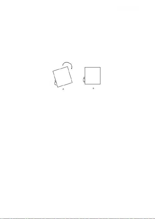
Please select the correct position for the switch. Install switch on DIN-RAIL
as following steps:
Insert the upper part of the DIN rail into the slot on the upper part of the
DIN rail connection base with the circlip. Slightly push down on the top panel of
the switch and rotate the device as below picture.
Insert DIN-rail into DIN-Rail slot and confirm the switch reliable installed
on the DIN-rail.
3.3.2. Cable connection
After the switch is correctly installed , you can install and connect the
cables,which mainly include cable connections of the following interfaces.
Operation port
The terminal equipment interfaces are Gigabit and 100M Ethernet RJ45
interfaces and gigabit optical ports, so it can be connected to terminal
equipment or network equipment by using direct network cables and optical
fiber cables
Power connect
The switch use power according to the instructions on the product label.
When all other cables are connected, you can connect to the power supply.
3.3.3. Fiber connection
This product has two full-duplex 1000Base-X single mode / multi mode
fiber interface and use hot-pluggable SFP during the optical interface using LC
connectors. Optical interface to be used in pairs (TX and RX as a pair), TX port
is the optical transmitting end,which is connected to the optical receiving end
RX of the another remote switch optical interface; RX ports is the optical
receiving end which is connected to the optical transmitting end TX of the same
remote switch optical interface. Two remote switches optical interfaces can be
connected by using 2 redundant 1000Base-X optical fiber interfaces at the
same time.
SFP optical module shown in the figure :
TELE2210G-2GF-8GT Full Gi
g
abit Din-rail mount Industrial Ethernet Switch
www.telefly.cn

- 8 -
Hot-pluggable SFP modules as follows:
Hot-plug procedure:
Observe the end with PCB gold finger during SFP
Insert the golden finger end into the metal shielding cage of the SFP, and
hear a clicking sound to indicate that the device has been inserted in place,
and then put the SFP plug-in handle on the normal position parallel to the
interface.Then it means we can use it.
Hot pull steps:
First pull the SFP's plug handle perpendicular to the interface,the optical
device should be disconnected from the hook of the SPF shielding cage at this
time.
Pull out the SFP module in parallel
Notice
This switch uses lasers to transmit signals on fiber optic cables. The
laser meets the requirements of Class 1 laser products and normal operation
is harmless to eyes. However, when the equipment is powered on, do not
look directly at the optical transmission port and the end face of the optical
fiber terminator.
The steps to connect the pluggable fiber optic module are as follows:
Remove and keep the rubber cover of the ST/SC/FC. When not use, put
on a rubber sleeve to protect the optical fiber terminator .
Check the optical fiber terminator if it is clean. Slightly moisten a clean
paper towel or cotton ball, and gently wipe the cable plug. Dirty optical fiber
terminator will reduce the quality of optical transmission and affect port
TELE2210G-2GF-8GT Full Gi
g
abit Din-rail mount Industrial Ethernet Switch
www.telefly.cn
- 9 -
performance
Connect one end of the optical cable to the optical interface, and the
other end to the optical interface of another device
After connection is completed, check the corresponding LINK/ACT
indicator of the fiber port on the front panel. If the indicator is on, the connection
is valid.
3.4. Simple test
3.4.1. System self-examination
When the device is powered on, all the indicator lights on the front panel
will flash once.When the RUN indicator flashes, the switch starts to work
normally.
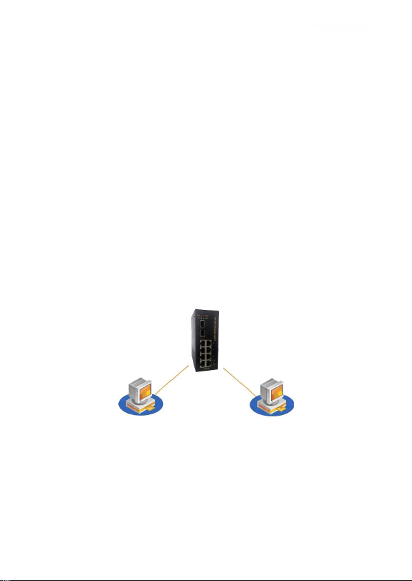
3.4.2. RJ45 port testing
As picture show below, power on the switch, connect any two RJ45 ports
to the network port of two test computers through a direct-connected network
cable, and send Ping commands to each other. Both can correctly ping each
other without packet loss. At the same time, the yellow light on the
corresponding port should be always on (computer network card is working in
1000M state) or always off (computer network card is working in 10M/100M
state), and the green light on the corresponding port should flash. It means that
the hardware of the tested two RJ45 ports is working normally.
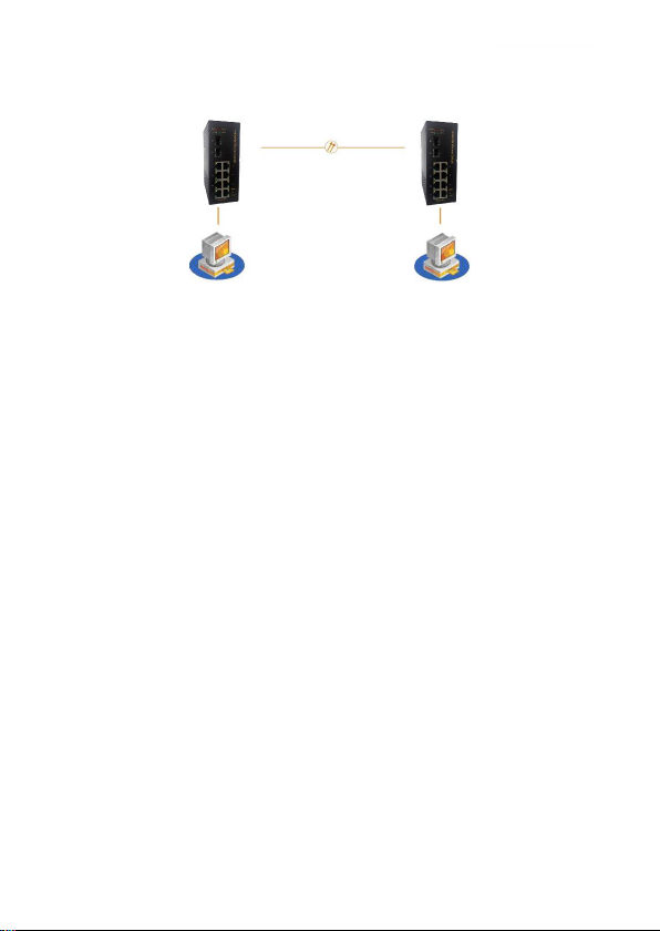
3.5. Fiber port testing
Combine the equipment with optical fiber interface into the optical fiber
chain network shown in Figure 3-10 (TX connects to another RX, RX connects
to another TX). Any RJ45 port of each device is connected to the test computer
through a direct-connected network cable and sends Ping commands to each
other. Both parties can correctly ping each other without packet loss. At the
same time, the LINK lights corresponding to the optical ports should flash,
indicating that the two optical ports under test are working normally. Figure 3-8
TELE2210G-2GF-8GT Full Gi
g
abit Din-rail mount Industrial Ethernet Switch
www.telefly.cn
- 10 -
is a schematic diagram of the optical port test in the TELE2210G-2GF-8GT
switch.
Figure 3-8 Schematic diagram of optical port test
TELE2210G-2GF-8GT Full Gi
g
abit Din-rail mount Industrial Ethernet Switch
www.telefly.cn

- 11 -
4. Maintain and service
The switch has 5 years’ guarantee according to the product specifications
of Maiwe, we will maintain or replace the product for free if has any problem
during the guarantee.However, the above commitment does not cover damage
caused by improper use, accidents, natural disasters, incorrect operation or
incorrect installation.
To ensure the customer’s benefit, we also provide some methods to help
the customer and solve their problem as followings:
Service on line
Call technical support office
Maintain or replace
4.1. On-line service
In our website,you can get more useful product information and usage
methods in the part of technical support.
4.2. Call for technical support service
when you have any problem, please contact our technical support
department at any time.Our engineer will give you reply and solve your
problem at first time.
4.3. Warranty Policy
As for product maintenance, replacement or return, you should first
confirm with the technical staff and then contact the sales and get the problem
resolved. The above should be handled in accordance with the processing
procedures of Co., Ltd.
.
Telefly Communications Equipment
TELE2210G-2GF-8GT Full Gi
g
abit Din-rail mount Industrial Ethernet Switch
www.telefly.cn
Table of contents
Other TELEFLY Switch manuals

Popular Switch manuals by other brands

HRT
HRT SW-HDMI-3A user manual

Moeller
Moeller DE5-LZ1 V Series installation instructions

Painless Performance Products
Painless Performance Products 50201 installation instructions

Jung
Jung 1180 Series Operation manual

ANTAIRA
ANTAIRA LMX-2012G-SFP Series Hardware manual

Renkforce
Renkforce RF-3353154 operating instructions


