Telefunken RT200 Operation manual

2011.X.27
Telefunken RT200
Device Type
Digital Synthesizer Tuner
Start of Sale
1981
Original Price
DEM 799,-
General Description
The medium-sized tuner of the Silver Series includes a feature even not present in the larger RT300: a
digital timer/clock, allowing to turn the tuner plus two other devices on and off at preselected times. A
single point of time and a daily-repeating time may be programmed. The tuner is never really off: the
power switch is in reality only a key that instructs the microprocessor to turn the relay for the outlets and
the tuner section off; the display then switches to a 24-hour time display. Since there are only five digits
available, the time display doesn't include the seconds.

In contrast to the RT300 and MT1, the other digital tuners in the Silver Line, the RT200 does not allow
entering a frequeny via the numeric keys. Note that '16 program memory places' means 8*FM and 8*AM;
you can't have more places in one range and less in the other!
Features
UKW/MW, 16 program memory places, manual and automatic station search, PLL tuning system, LED
signal strength indicator, exact tuning indicator, digital timer clock, mono switch, AFC (switchable)
Connectors
AF Output (DIN and Cinch), Antenna (75 Ohms asymmetric 240 Ohms symmetric AM/FM), 2 switched
outlets for timer operation
Technical Data
(taken from the user's manual and the service manual; I took the values from the service manual in case of
contradictions)
FM Receiver
Wave Band:
87.5 - 108 MHz
Circuits:
11, 4 adjustable
Sensitivity:
0.8 µV / 2.6 µV Mono/Stereo
at 26 dB at 75 Ohms
1.6 µV / 5.2 µV Mono/Stereo
at 26 dB at 300 Ohms
Limit Range:
<1.0 µV for -3 dB at 75 Ohms
Intermediate Frequency:
10.7 MHz
IF Bandwidth:
160 kHz
Selection:
65 dB (2 signal method)
Mirror Selection:
>=70 dB
Capture Ratio:
<1 dB
Phase Suppression:
>55 dB
Carrier Signal Suppr.:
>70 dB
Frequency Response:
10 Hz - 16.0 kHz
Distortion Factor:
<0.5 % stereo
<0.3 % mono
at 1 kHz and 40 kHz deviation
Cross Talk Dampening:
>38 dB at 1 kHz
>30 dB at 12.5 kHz
Voltage Ratio:
>62 dB stereo (eff)
>65 dB mono
S/N Ratio:
>64 dB stereo
>67 dB mono
Range of Strength Display:
1 µV - 2 mV
Accuracy of Standards:
0 digit for station frequency in 50 kHz steps
AM Receiver
Wave Band:
MW 522 - 1611 kHz

Sensitivity:
9 µV at 600 kHz
(at 1 kHz 30% Modulation)
Circuits:
6, 2 adjustable
Intermediate Frequency:
450 kHz
IF Bandwidth:
4.8 kHz
Voltage Ratio:
36 dB at U = 1 mV,
Accuracy of Standards:
+/- 1 digit
Range of Strength Display:
8 µV - 5 mV
Frequency step:
9 kHz
General
Components:
13 Integrated Circuits
42 Transistors
43 Diodes, 20 LEDs
Mains Connection:
220 V
Fuses:
1 x T 2.5 A (primary)
1 x T 630 mA
1 x T 100 mA
Dimensions:
435 x 56 x 250 mm
Weight:
~ 4.5 kg
Common Failures
Leaked Accumulator
The RT200 contains a 4.8V NiCd accumulator pack. This is needed to keep the processor and the clock
running while the device is disconnected from the mains supply (as I noted above, the microprocessor and
its supply is still on when you turn the tuner off). During normal operation, the accumulator will be
recharged. However, there is no protection against driving the accumulator into deep discharge when the
tuner is disconnected from power for a longer period of time. Similar to the accumulators on older PC
mainboards, this will (1) destroy the NiCas and (2) make them leak! If you see a pack with the white,
crystal-looking electrolyte leaked out, immediately replace it, since the acid can also destroy traces on the
PCB. The cells used in the pack have a non-standard size. Simply use a pack of four standard AA/R6 cells
and connect it via some inches of wire to the PCB. Even the smallest AA cells available these days have
four times the capacity of the original cells, and there is plenty of space in the case to install the new pack
somewhere.

Out of Tune
The second next common failure is a synthesizer crystal out of tune. This becomes notable by the tuner's
exact-tuning display: though the correct frequency for a certain station is set, the exact-tuning indicator
does not 'show green'. Typically, it will claim a mistune towards lower frequencies. Since the tuning
principle is a PLL synthesizer with a closed loop, aging of analog components like the varicaps or OpAmps
is out of question, the synthesizer's reference clock must be wrong - just by a couple ppm, but enough...
You may try swapping the crystal, but since you will need to readjust the oscillator anyway, you may try to
get the old one back to the correct frequency: the crystal is stabilized with two small ceramic capacitors.
Their purpose is to assure a correct start and a stable oscillation, and they also have the property of slightly
reducing the crystals resonance frequency. They are located between the crystals's contacts and ground. Try
reducing their values (one of them is adjustable, but that is usually not enough) or unsolder them. For
example, I had an RT200 that came 'back into tune' after I removed C272...
Linked to the out-of-tune phenomenon is the tuner's incaopability to reliably receive in stereo; an RT200
going mono in the music's rhythm is not uncommon ;-)
Failed +5V Supply
In case the tuner starts acting 'funny' or the display stays dark altogether, it's worth to check the +5V supply
of the microprocessor. If it is more than half a volt too low, try to swap the regulating transistor for the +5V
supply, T236. Seems this transistor is slightly underdimensioned and may get 'cooked' over time. I usually
replace it with a BD135 plus a small heatsink.
Broken Processor
Another failure I had so far was a broken microprocessor (which is a complete project on its own, see
below), but this is surely not a standard failure and more due to incompetent handling/repair of the previous
owner...
Spare Part Numbers
(taken from Telefunken's 1981-1991 Service Handbook and the Service Manual)
ICs, Transistors,
Diodes
IC201
IC TA7060 AP
339 575 227
IC202
IC HA12412
339 575 228
IC203
IC LB1450
339 575 278
IC204
IC LA1245
339 575 285
IC205
IC LB1426
339 575 279
IC206
IC TCA4500A
339 575 284
IC207
IC NJM4558D
339 575 087
IC208
IC MN6147
339 575 281
IC209
IC MN1455LF (IC209)
339 575 280
IC210
IC MC1741 (IC210)
339 575 123
IC211
IC MB74LS42 (IC211)
339 575 282
IC212
IC NJM7812A (IC212)
339 575 283
transistor BF451
339 556 289
transistor BC639
309 001 313

T204-207,209,224,228,
transistor 2SC1815Y
339 556 292
229,231,233,234,237,
238
T201
transistor 2SC380
339 556 052
T202
transistor 2SK212D
339 556 453
T203
transistor 2SK212C
339 556 454
T208-225,210-223,227,
transistor 2SA1015
339 556 216
230,232
T235
transistor 2SA1020
339 556 456
T236
transistor 2SD592
339 556 455
T101
transistor 3SK45B
339 556 456
T102,104
transistor 2SC535B
339 005 901
T103
transistor 2SC461B
339 005 925
D201-204,207,208
diode 1S446
309 327 925
D205,206
diode KV1225
339 529 322
D209-214,217,220-223,
diode 1S1555
339 529 017
304,305,501-504,506)
D215,216,218,224,225,
diode SR1K
339 529 101
229,230,303
D219
diode KB262
339 529 092
D226
diode DBA10B
339 529 368
D227
diode 05Z7,5X
339 529 317
D228
diode 05Z6,8Z
339 529 318
D301,302
diode 05Z16X
339 529 319
D101-104
diode 1SV53F2
339 529 314
D105
diode 1S2687C
339 529 315
D520,522,523
LED SR531D
339 529 323
D521
LED SG231D
339 529 320
D524-528
LED LN05202P
339 529 321
D503
LED SLP135B
339 529 324
rectifier
339 520 051
Filters
FL201,202
low-pass filter
339 368 014
CF201
ceramic filter 10.7MHz
339 367 116
CF202
ceramic filter 10.7MHz
339 368 016
CF204,205
ceramic filter
339 367 132
L201
coil 10.7MHz (L201)
339 347 039
L202
lowpass filter 195 kHz
339 367 117
L203
choke coil 2.2µH
339 348 655
L204
coil 3.3mH
339 347 045
choke coil 220µH
339 347 038
L206
antenna coil
339 347 139
L207
oscillator coil 100µH
339 347 138
L208
coil
339 367 114
L209
coil
339 367 115

L210,211
choke coil 39µH
339 347 040
symmetrical transformer
339 312 114
L101
coil
339 347 134
L102,104
coil
339 347 135
L105
coil
339 347 136
L108
oscillator coil
339 347 143
L106
coil
339 347 137
L107
coil
339 367 113
Misc. Electrical Parts
accumulator 4.8V
339 283 128
key
339 442 121
mains button w. rod
339 202 109
push button
339 222 132
push button
339 222 124
push button, 2 fold
339 222 125
push button, 3 fold
339 222 126
tuning knob
339 222 123
J201
antenna socket
309 670 928
J202
DIN socket, 5 poles
339 540 114
J203
cinch socket
339 540 146
FLU201
digital display
339 335 108
FU201
fuse T2.5A
309 627 916
FU202,203
fuse T400mA
339 572 004
FU204
fuse T100mA
339 570 023
R220,267
var. res. 10KOhm
339 508 651
R246,279,286
var. res. 20KOhm
339 508 653
R355
var. res. 5KOhm
339 502 015
RY201
relay
339 360 108
S201
push button assembly
339 442 119
XTAL201
crystal 4.5MHz
339 349 154
battery 4.8V/150mAh
339 168 006
FM mixer board
339 337 145
C101,109,112
trimmer
339 510 061
C124
trimmer
339 510 062
station buttons board, cpl.
339 337 137
tact switch w/o diode
339 442 020
tact switch w. diode
339 442 018
scanning board, cpl.
339 442 130
key assembly for it
339 442 120
mains socket
339 480 107
mains switch
339 442 121
mains transformer
339 312 112
mains cable
339 480 106
Misc. Mechanical Parts
cable binder
339 911 713

front plate, cpl.
339 132 128
side part f. front plate
339 232 125
frame f. tuning knob
339 222 145
button frame
339 222 144
buttons guiding, 8 fold
339 222 143
indicator window
339 272 128
display frame
339 337 142
push button holder
339 917 111
push button spring
339 917 110
housing, upper part
339 112 107
housing, rear panel
339 137 110
foot
339 062 112
Available Documents
Manual
Service Manual/Circuit Diagram
Goodies
xxxxxxxxxxxxxxxxxxxxxxxxxxxxxxxxxxxxxxxxxxxxxxxxxxxxxxxxxxxxxxxxxxxxxxxxxxxxxxxxxxx
Replacing The Broken Microprocessor in a Telefunken RT200
Introduction
NOTE: This is a project for people who are absolutely crazy, like me. It took me altogether more than two
months of work to do this project, not counting the hassle to find appropriate information (and realizing
that I had to find out things myself). This report mostly has documentational purposes and there is probably
noone who has an RT200 with the same problem and can use this text as a 1:1 guide. To do something like
this, you need to have experience in reverse engineering devices, understanding both analog and digital
electronics, building hardware, and programming embedded controllers. If you try something similar along
the lines of this project, you are absolutely on your own and I might not be able to help you out. Especially,
you are yourself responsible for anything you break. So for the moment, lean back, read, enjoy, and see if
you can reuse some aspects for your projects.
The root of this project is one of my collecting passions, Telefunken Hifi components built in the late
70s/early 80s. The RT200 is an FM/AM Tuner with a built-in timer clock, i.e. you may use it to switch
other devices on and off at preprogrammed times. Typically, those were the cassette deck and/or amplifier,
either to wake yourself in the morning with a sound quality better than any alarm radio clock or make
unattended recordings of radio programs.
I bought this RT200 for a few bucks at a flea market. Normally, there are few things in a synthesizer-based
digital tuner that can break: no movable parts except for the buttons, no lamps to burn out, just a NiCd
accumulator that may start to leak after a couple of years of operation. This RT200 however was perfectly
dead: plug it in and you won't get any reaction to key presses, just a few cryptic symbols on the display.
Checking the parts that are usually broken in such a case (power supply, clock generator) revealed nothing,
so it was clear that the central microprocessor chip had passed away. A truly uncommon event, so I guess
this happened due to incompetent repair attempts by the previous owner.

Contents
Some Reverse Engineering
Since the tuner's PCB is single-sided, it is principally possible to reverse-engineer the device by following
the traces, but at least in Germany, there is a much simpler way: go to www.schaltungsdienst.de, the web
page of the Lange circuit service in Berlin. This company offers a unique service: it archives schematics
and manuals for about any piece of audio/video equipment that was ever sold in Germany. Manufacturers
usually only have schematics for the newer devices, but Lange always gets a copy of the schematic and
stores it (hopefully) forever. It might even happen that when you ask a manuacturer for an older schematic,
they will automatically forward your request to Lange. Of course this service is not free; expect about
20..40 DEM plus shipping, depending on the number of pages to copy. I however think that this is well
worth the money, given the amount of time and nerves you save. Fortunately, this schematic already gives
the pin functions of the central microprocessor IC (a Matsushita MN4500 by the way, but that doesn't help
anyone...):
Pin
No.
Name
Direction
Function
1
Vss
----
Ground
2
LW
Output
goes high if switched to long wave AM (unused on the RT200)
3
MW
Output
goes high if switched to medium wave AM
4
FM
Output
goes high if switched to FM
5
OUTLED OUT
Output
goes high to turn tuner on
6
MUT OUT
Output
goes high to mute the AF output
7
LATCH OUT
Output
controls data transfer to the synthesizer chip
8
DIGIT OUT 5
Output
row selectors for the display/keyboard matrix
9
DIGIT OUT 4
Output
"
10
DIGIT OUT 3
Output
"
11
DIGIT OUT 2
Output
"
12
DIGIT OUT 1
Output
"
13
DIGIT OUT 0
Output
"
14
KEY IN 0
Input
sense lines for the keyboard matrix
15
KEY IN 1
Input
"
16
KEY IN 2
Input
"
17
KEY IN 3
Input
"
18
STAT DET
Input
goes high when a signal of sufficient quality is received; needed for
auto scan
19
PWR DET
Input
issues a 'reset pulse' after the main supply comes back
20
KEY IN 4
Input
sense lines for the keyboard matrix
21
KEY IN 5
Input
"
22
BCDOUT 0
Output
contols the decoder driving the station key LEDs
23
BCDOUT 1
Output
"
24
BCDOUT 2
Output
"
25
BCDOUT 3
Output
"
26
TEST
Input
unused input
27
RESET
Input
low-active reset for the CPU
28
GND
----
Ground
29
LOCKDET IN
Input
goes high when the synthesizer's PLL has synchronized to the
programmed frequency

30
CLOCKIN
Input
250Hz clock from the syntesizer chip for the internal timer
31
SEGMENT OUT
0
Output
segment data for the display + addr/data for the synthesizer chip
32
SEGMENT OUT
1
Output
"
33
SEGMENT OUT
2
Output
"
34
SEGMENT OUT
3
Output
"
35
SEGMENT OUT
4
Output
"
36
SEGMENT OUT
5
Output
"
37
SEGMENT OUT
6
Output
"
38
SEGMENT OUT
7
Output
"
39
Vdd
----
5V supply voltage
40
CPU CLOCKIN
Input
CPU clock input (562.5kHz)
Luckily, these are all only digital functions and the processors works with a standard 5V supply and TTL
levels, which simplifies the selection for a new processor:
Selecting a Microprocessor Platform
The microcontroller market offers lots of different families and variants of controllers. Some of them are
well-known and for general-purpose use, some of them were designed with a specific application in mind.
Since the synthesizer's PLL loop (see below) is completely done in the PLL chip, the main CPU's
functionality mainly consists of driving the multiplexed display, querying the keys, running the internal
clock for the timer and moving around some data - all not very advanced tasks even a 4-bit CPU could
handle (I guess the original MN4500 is a 4-bit CPU!), but most 4-bit-CPUs are not general purpose and
difficult to get or require expensive development systems, so let's settle with an 8-bit core. What other
things do we need?
Must be available in CMOS, to allow operation from the built-in accumulator for power failures or
for times when the tuner is not connected to a mains supply.
Must be able to run with the slow 562.5kHz clock supplied by the synthesizer chip. Of course we
could add an own oscillator, but I already said that there is no need for much compute power and
the low clock helps keeping the power consumption low.
Must be available without problems. Not yet another obscure chip ;-)
Development tools must be available for free at best...
Summing up, I settled with a CPU family that is the most widely used family of 8-bit controllers: The 8051
family. Originally introduced by Intel, 8051 derivatives are available from more than a dozen of
manufacturers. The two 'standard' ROMless components 8031 and 8032 are available from probably more
than 10 different manufacturers. I finally settled for the 80C32, the variant with more internal RAM
(needed for the stations' frequency storage) and a third timer (not needed here). By coincidence, I got an
TS80C32X2 from Temic, formerly Telefunken Microelectronics. It has the nice capability of running in X2
mode, i.e. an internal frequency divider is turned off and the device runs at double speed with the same
external clock. A very nice feature, especially considering the low external clock frequency.
The other stuff around the CPU is pretty basic: an address latch to demultiplex address and data lines, an
EPROM for the code (the C32's internal RAM of 256 bytes is sufficient for this task), and some latches and

bus drivers for additional parallel I/O: since the external memory interface eats a lot of I/O lines, an I/O
expansion is necessary in some way. I could have used one of the more modern x51 variants with built-in
flash EPROM and thereby get most of the processor's pins as I/O, but as I already mentioned, I have a
strong preference for components that are not single-sourced.
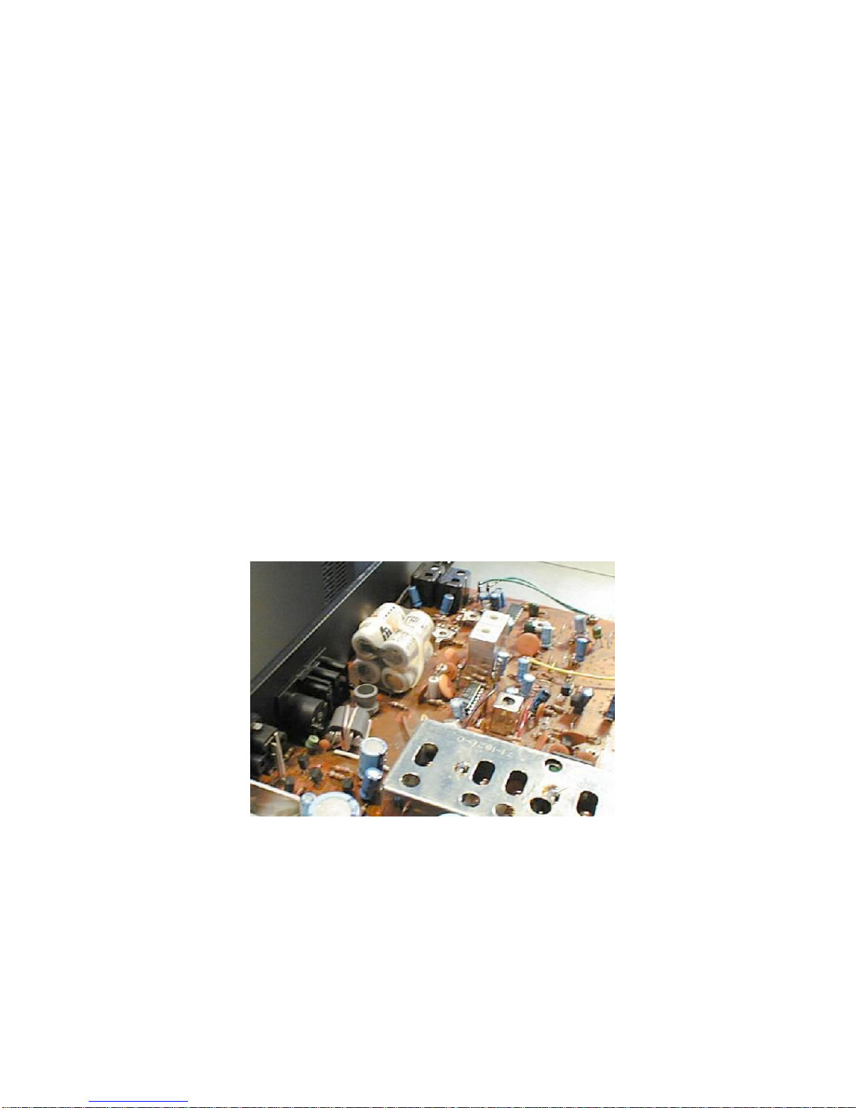
The whole circuitry is built on a prototype card and wired with thin isolated copper wires, a popular
method for prototypes. Needs a bit patience and requires accuracy...the connection to the tuner's mainboard
is done via a ribbon cable with a crimped plug on one end and an IC socket on the mainboard; of course, I
had to unsolder the broken processor and replace it with a socket. The DIL connector is in my case a
simple IC socket with the cable soldered onto it wire by wire; there are however also crimpable connectors
available for this end.
Basic Layout of the Software
As you may imagine, it is by far too complex to explain the firmware on a line-by-line basis at this place;
I'm also not going to explain the basics of the 80C32's architecture at this place - there's plenty of literature
available in the Internet about that. I will therefore describe the basic building blocks and line out how they
work together:
Initialization
Of course, the first step after a power-on or a reset is the initialization. The interrupt-driven background
processes have to be initialized, and some global memory cells are resetted to meaningful defaults.
Interrupt Routines
There are two interrupt-driven background processes that run on the CPU. At least on a standard C32
without X2 mode, they consume about 70% of the CPU time, which is no miracle given the low clock
frequency. The remainder is however still fully sufficient for our purposes.
The first process runs at about 400 interrupts per second and is used to drive the flourescent display and
read the keyboard matrix. As with most consumer electronics, the RT200's display is a 'dumb' display that
does not the refresh by itself, so the processor has to do the multiplexing itself. It works in the following
way: Initially, the CPU outputs the data for the leftmost digit to the SEGMENT OUT pins and pulls the
DIGIT OUT 0 line low while DIGIT OUT 1..4 remain high; this way, the contents of the leftmost digit are
displayed at the correct place. In the next cycle (==interrupt), the first digit is turned off, the data for the
second digit outputted, and the second digit is turned on. This process continues until the last digit is done,
and we jump back to the first digit. So at any point of time, only one digit is on, but if this done fast
enough, you get the impression of a still display. Similar to a computer monitor, about 60..70 complete
cycles are needed per second for a flicker-free display, which results in the interrupt frequency mentioned
above for 6 digits.
The other regular process is an interrupt service routine triggered by the precise 250Hz delivered by the
synthesizer chip. This clock is used to run a real-time clock needed for the time display and timer
functionality. For each interrupt, a byte in memory is incremented. As soon as its value reaches 250, the
seconds value is incremented. The rest should be clear ;-)
Since the keyboard matrix and display share their row select, is is only natuaral that the process mentioned
first also scans the keyboard. If one row of the matrix is pulled low, any key that is pressed and connected
to that row will generate a low level on the keyboard scan lines. The scanned values are stored in 6
consecutive memory cells, resulting in an image of the keyboard matrix stored in memory that gets updated
regularly. The x51 family allows to assign either a low or a high priority to each interrupt source. In our
case, the keyboard/display multiplexer gets a high priority, while the clock update process works with the
standard (low) priority. This is necessary to allow the multiplexer to interrupt a running clock service
routine. Especially when one or more counter(s) roll over, the clock update consumes more time and can
significantly delay the next multiplex cycle (don't forget we have a rather slow 8032!) and result in a

visible sort of 'flicker' resulting from some segments being turned on longer than others and therefore
seeming to be brighter.
Main Loop
The RT200 has a row of buttons that release each other and define the current 'operating mode' of the
tuner's 'user interface':
Timer On: Normal tuner operation, timer function enabled;
Timer Off: Normal tuner operation, timer function disabled;
Timer Set: (Re)program timer settings;
Timer Check: Recall/display timer settings;
Timer Cancel: Erase timer settings;
Clock Set: Set the timer's clock.
Once the system is initialized, the CPU contiuously queries which button is pressed and branches into the
appropriate sub-handler. Normally, this handler immediately returns to the main loop once the appropriate
actions are done, but it may decide to delay this return in case a multi-key entry (time or frequency) is
made. Of course, such an entry is immediately terminated in case the operation mode changes, so the key
input routines inside these handlers also regularly check the current mode.
The Timer Section
is not overly complex: The handler for the 'Timer On' and 'Timer Off' modes is basically the same. in
'Timer On' mode, this handler is additionally followed by another routine that compares the current time
against the preprogrammed timer values and issues the appropriate on/off sequences when necessary. This
check is only done if the seconds value is zero; i.e. there is no problem with the background interrupt
process updating the time in the same moment this routine runs. Problems only would occur if the
comparison took longer than a minute...
Programming the Synthesizer Chip
The probably hardest part was the programming of the synthesizer chip, the chip responsible for selecting
the frequency to be received. Its function is to generate a freely programmable frequency that is mixed with
the amplified and coarsely preselected signal from the antenna. When you mix two frequencies properly,
you get as a result two new signals with a frequency of the sum resp. difference of both frequencies. In our
case, only the difference is interesting. If we program the synthesizer with a frequency that is higher than
the signal to be received by a fixed amount, the difference remains constant and the following circuits need
not be tunable; they can be accurately adjusted for this frequency. This principle is called Superhet
Receiver in contrast to a Straight Receiver where all circuits have to be tuned synchronously to the
frequency of the station to be received. Though this is in theory doable, it becomes extremely difficult to
keep more than two variable circuits 'in tune'. Two circuits is however not enough for a good selection, so
practically all radio receivers, including the simplest pocket radios, are superhet-type receivers.
The synthesizer chip generates a variable frequency with a tunable oscillator whose frequency is divided
and compared to a given reference clock. The difference signal is fed back to the oscillator's tuning
circuitry. As soon as the oscillator is 'in tune' (i.e. the regulator doesn't have to correct any more), the
oscillator outputs a frequency that is the reference clock multiplied by the divisor. So if we make the
divisor programmable, we have an oscillator with a programmable frequency!
In case of the RT200, a Matsushita MN6147 is used that contains the reference oscillator, frequency
comparator/regulator, and the programmable divider. The oscillator is an LC-circuit inside the RF frontend
that contains a Varicap diode. A Varicap is a diode that operates in blocked direction and varies its
parasitic capacitance according to a DC voltage applied to it.
From the schematic, we get the MN6147's pinout:

Pin No.
Name
Direction
Function
1
Vss
----
Ground
2
OSC OUT
Output
Goes high if PLL has locked
3
OSC1
----
Connect to 4.5 MHz crystal
4
OSC2
----
"
5
CLOCK1
Output
562.5 kHz clock for CPU
6
CLOCK2
Output
250 kHz clock for CPU timer
7
VCC CLOCK
----
+5V supply
8
PD OUT
Output
Output of Varicap voltage
(externally amplified with 741 OpAmp)
9
LATCH CLOCK
Input
control signal from CPU
10
DAIN 3
Input
Data/Address input from CPU
11
DAIN 2
Input
"
12
DAIN 1
Input
"
13
DAIN 0
Input
"
14
VCC
----
+5V supply
15
AM LOIN
Input
Input from AM oscillator
16
FM LOIN
Input
Input from FM oscillator
17
SW/MW
Input
Select short or medium AM wave band
(unused, tied low)
18
FM/AM
Input
Select AM or FM operation
Though this helps understanding the circuitry, it doesn't help us with out new firmware, since there is no
information about how to program the synthesizer to a certain frequency. After a couple of phone calls
with Panasonic/Matsushita Germany, it was clear that I would have had to contact the japanese mother
company to get this piece of information (the people I spoke to however were quite friendly and trying to
help me, I must add at this point!).
Since I also own a still working RT200, there was a simpler way of finding things out: take a working
sample, tap onto the data and clock lines, and see what is happening when the frequency changes. I was
able to use a digital logic analyzer from HP for this job:

Shown on the LA's display is the result of a single programming cycle. The synthesizer chip contains a
couple of registers, each 4 bits wide. With a low-to-high transition of the clock line, a certain register is
selected; with a high-to-low transition, data is written to the addressed register. So a single write operation
consists of the following steps:
Apply register address to data lines
Pull clock line high
Apply register data to data lines
Pull clock line low again
The frequency to be programmed (remember this is 10.7 MHz resp. 450 kHz higher than the frequency
ultimately to be tuned) is simply written in BCD code to the synthesizer's registers. Specifically:
Write 0 to register 2
For FM:
oWrite 1 to register 1
oWrite hundreds of MHz to register 3
oWrite tens of MHz to register 4
oWrite ones of MHz to register 5
oWrite hundreds of kHz to register 6
oWrite 2 to register 7 if +50 kHz, otherwise write 4
For AM:
oWrite 2 to register 1
oDivide frequency by 9
oWrite hundreds of kHz to register 3
oWrite tens of kHz to register 4
oWrite ones of kHz to register 5
oWrite 0 to register 6
oWrite 0 to register 7
Write 7 to register 8
Note that in AM mode, you can only tune in 9 kHz steps!
Adding a Remote Control Input

The larger brother of the RT200, the RT300, features a remote control input to control the tuner via the
infrared remote control receiver in the RP300 pre-amplifier. Now that we have a firmware we can extend
and modify easily, there is no reason not to add some nice features you had always been missing...
The RP300 contains a Siemens infrared receiver & decoder chip that outputs the code of the pressed button
as a 6-bit-code (all bits zero means that no button is pressed). For the 'less intelligent' devices like the
cassette deck or the record player, some logic decodes these codes into individual signal lines for the
controllable functions. The tuner in contrast directly gets the 6-bit-code and has to do the decoding itself.
The reason for this is simple: About 20 buttons of the remote control are assigned to the tuner, and you
only have 8 pins in the used DIN connectors. Of course this also saves I/O pins at the tuner's processor, and
what is more interesting: the tuner also can 'see' codes destined for other devices in the system and react on
them. For example, if you turn the system off via the remote control, the tuner can also turn itself off
automatically. And what is more interesting: The buttons on the RP300's front panel run via a virtual
remote control whose signal is merged with the IR receiver's output, the tuner also can notice when you
switch the signal source to 'Tuner' and turn itself on. Another goodie I added to display the selected signal
source on the tuner's display for a few seconds. Adding the remote control input was relatively simple: the
signal are fed into the system with an extended low-level keyboard scan routine. Whenever a higher-level
routine queries the keyboard, this routine first checks the remote control input for a non-zero code and
returns this code in case the code translates to a 'usable' button. Otherwise, the normal key matrix scan is
initiated.
Actual Implementation
Below is a photo about how I installed the board in the RT200.
There is space in abundance in the right half of the cabinet, enough to install a standard Eurocard-sized
prototype board (160x100mm). Since this was a singular project, I didn't feel the need for a real PCB (and
the circuitry underwent quite a couple of changes...). a 40-wire ribbon cable connects the board to the
socket of the old processor. I could have used one of these handy DIL connectors for the cable, but you
know, it was Saturday and all shops were closed...Due to the low clock frequency, such a long cable is not
a problem except for slight interferences during AM receival (who needs that in a Hifi tuner anyway...). All
connections, including power supply, are made via this ribbon cable. The only other connector is the
RP300 remote control input in the rear right corner.

Program Source
The program's assembler sources are available . To assemble them, you need my own cross assembler AS,
;***************************************************************************
; *
; RT200 Firmware *
; *
; Changes: *
; 2000-08-30 /AArnold - hour digit 3..9 immediately jumps to hours ones *
; - clear AM+FM after entering start time *
; 2000-09-04 /AArnold - begun decrementing frequency *
; 2000-09-05 /AArnold - begun programming synthesizer *
; 2000-09-10 /AArnold - tuning works :-) *
; 2000-09-11 /AArnold - added usage of program keys *
; 2000-09-12 /AArnold - autorepeat up/down *
; 2000-09-13 /AArnold - started digital frequency input *
; 2000-09-14 /AArnold - added search + PLL lock inputs *
; - mute during PLL adjustment *
; 2000-09-16 /AArnold - mute during freq. wrap *
; 2000-09-17 /AArnold - bail out during AM freq input,search *
; - symbolically calculate delays *
; 2000-09-22 /AArnold - turn off station LED before search *
; - switch to 256 Byte RAM *
; 2000-09-28 /AArnold - add remote control handling *
; 2000-09-30 /AArnold - remote control decoder *
; 2000-10-01 /AArnold - display other input sources *
; - remote ctrl off always turns off *
; 2000-10-03 /AArnold - added step functionality *
; 2000-10-07 /AArnold - only check timer once a minute *
; 2000-10-15 /AArnold - version 1.0 *
; 2000-11-12 /AArnold - do not overwrite band info when tuner is *
; already off *
; 2001-03-02 /AArnold - fix typos in clearing once on/off times (damn!) *
; add copyright string *
; version 1.1 *
; *
;***************************************************************************
cpu 8052
temic equ 1
include "stddef51.inc"
include "bitfuncs.inc"
if temic
ckcon equ 08fh
endif
;---------------------------------------------------------------------------
; macros:
regbank macro no ; register selection
if no & 1
setb rs0
elseif
clr rs0
endif
if no & 2
setb rs1
elseif
clr rs1
endif
endm

proc macro name ; procedure frame
section name
public name
name label $
endm
endp macro
endsection
endm
ljnz macro dest
jz skip
ljmp dest
skip:
endm
ljc macro dest
jnc skip
ljmp dest
skip:
endm
;---------------------------------------------------------------------------
; constants
rawclk equ 562500 ; input clock to CPU (4.5 MHz / 8)
timeclk equ 250 ; TOD clock
timeperiod equ 1000/timeclk
digits equ 6 ; # of digits in display
delval function time,time/timeperiod
disprate equ 68 ; desired display refresh rate in Hz
if temic
t0rate equ rawclk/6/digits/disprate ; -->timer 0 reload value
else
t0rate equ rawclk/12/digits/disprate ; -->timer 0 reload value
endif
; operation modes given by switches
enum mode_cset,mode_check,mode_tset,mode_cancel,mode_on,mode_off
enum reg0,reg1,reg2,reg3,reg4,reg5,reg6,reg7
KEY_UP equ 14 ; misc. keys
KEY_DOWN equ 15
KEY_AM equ 9 ; why this double-mapping???
KEY_FM equ 8
KEY_PHONO equ 10
KEY_AUX equ 11
KEY_TAPE equ 12
KEY_TUNER equ 13
KEY_REMOFF equ 16
KEY_STORE equ 17
KEY_FREQINP equ 18
KEY_OFF equ 19
KEY_STEP equ 20
KEY_NONE equ 0ffh
NUMPROGS equ 8 ; reduce to 4 for 8031
MIN_FM equ 0845h ; frequency ranges:
MIN_FM1 equ (MIN_FM|8000h)-1
MAX_FM equ 1130h
MAX_FM1 equ MAX_FM|8000h
DEF_FM equ 0875h
MIN_AM equ 0504h

MIN_AM1 equ 0495h
MAX_AM equ 1710h
MAX_AM1 equ 1719h
DEF_AM equ 0522h
;---------------------------------------------------------------------------
; data definitions
ON bit p1.7 ; control bits: turn device on
FM bit p1.6 ; switch AM prt on
AM bit p1.5 ; switch FM part on
MUTE bit p1.4 ; mute audio output
LATCHCLK bit p1.3 ; clock to synthesizer
LED bit p1.2 ; diagnostic LED
LOCK bit p1.1 ; PLL lock input
STATION_DET bit p1.0 ; station detection from strength indicator
PORT_AUX equ 0 ; 4-2-10 decoder
PORT_ROW equ 1 ; display+kbd row selection
PORT_COL equ 2 ; display data
PORT_KBD equ 0 ; keyboard sense
PORT_REM equ 1 ; remote control data
segment data
org 20h
dispdata: db digits dup (?) ; segment data is bit-addressable
__dig0 sfrb dispdata+0
STORE bit __dig0.2
MHZ bit __dig0.4
KHZ bit __dig0.7
__dig2 sfrb dispdata+2
dig2dot bit __dig2.0
__dig3 sfrb dispdata+3
dig3dot bit __dig3.0
auxdata: db ? ; data for LED 0..9 port
; things that need not be bit-addressable
clk_msec: db ? ; current time
clk_sec: db ?
clk_min: db ?
clk_hour: db ?
time_permon: db ?,? ; timer values
time_permoff: db ?,?
time_onceon: db ?,?
time_onceoff: db ?,?
prog_perm: db ? ; program to turn on for permanent timer
prog_once: db ? ; program to turn on for one-shot timer
; an FM program contains the frequency in BCD coding. Since the 100s position
; is only one bit wide, we use the upmost bit for the +50kHz step and the
; upmost nibble remains in the valid BCD range.
;
; for example, 94.80 is stored as 0948h, 100.55 is stored as 9005h
;
; an AM program also contains the frequency in BCD coding, it is just a bit
; simpler since the 4-digit kHz value perfectly fits onto 2 bytes :-)
;
; for example, 522 is stored as 0522h, 1611 is stored as 1611h
am_progs: db NUMPROGS dup (2 dup (?)) ; stored programs
fm_progs: db NUMPROGS dup (2 dup (?))
am_prog: db 2 dup (?) ; current programs
fm_prog: db 2 dup (?)

currband: db ? ; AM/FM selected ?
keydata: db digits dup (?) ; input from keyboard matrix
lastkey: db ? ; last key read
firstdel: db ?
stack: org 0d0h ; reserve 48 bytes of stack
db 30h dup (?)
;---------------------------------------------------------------------------
; reset/interrupt vectors
segment code
org 0 ; reset entry
start: ljmp resinit
org 3 ; IE0 entry (250 Hz signal)
ljmp clkserve
org 0bh ; TF0 entry (display multiplexer)
ljmp dispmux
;---------------------------------------------------------------------------
; store date & time here for identification
org 20h
db "RT200 Firmware (C) 2001 Alfred Arnold"
db " Build Date - Time : ",date," - ",time
;---------------------------------------------------------------------------
; since we want the copyright info in plain text, we have to redefine the
; character set afterwards!
charset 'E',10 ; shrunk charset
charset 'r',11
charset 'o',12
charset 'n',13
charset 'S',14
charset 'y',15
charset 'C',16
charset 'A',17
charset 'P',18
charset 'h',19
charset 'U',20
charset 'X',21
;---------------------------------------------------------------------------
; reset initialization
resinit: mov sp,#stack ; set start of stack
setb ON ; turn tuner off
setb MUTE
clr AM
clr FM
clr LATCHCLK
setb LED
if temic ; turn on TEMIC X2 mode
mov ckcon,#1
endif
regbank 1 ; preset variables for dispmux handler:

mov r2,#1 ; row shifter
mov r1,#dispdata ; data pointer displ-matrix
mov r0,#keydata ; data pointer kbd-matrix
regbank 0
setb it0 ; IE0 is level-triggered
setb ex0 ; enable external interrupt 0
clr px0 ; 250 Hz interrupt has lower priority
mov tmod,#32h ; T1 stopped, T0 in mode 2, no gate
mov th0,#(256-t0rate) ; set display mux interrupt rate
setb tr0 ; turn or timer 0
setb et0 ; interrupts on for timer 0
setb pt0 ; high priority
clr a ; preinit clock
mov clk_msec,a
mov clk_sec,a
mov clk_min,a
mov clk_hour,a
mov r0,#4 ; preinit timer values to invalid times
mov r1,#time_permon
initimer: mov @r1,a
inc r1
setb acc.7 ; (meaning bit 7 in hours is set )
mov @r1,a
clr acc.7
inc r1
djnz r0,initimer
mov a,#0fh ; preinit timer programs
mov prog_perm,a
mov prog_once,a
mov fm_prog,#lo(DEF_FM) ; preinit FM programs to 87.5 MHz
mov fm_prog+1,#hi(DEF_FM)
mov r0,#NUMPROGS
mov r1,#fm_progs
initfm: mov @r1,#lo(DEF_FM)
inc r1
mov @r1,#hi(DEF_FM)
inc r1
djnz r0,initfm
mov am_prog,#lo(DEF_AM) ; preinit AM programs to 522 kHz
mov am_prog+1,#hi(DEF_AM)
mov r0,#NUMPROGS
mov r1,#am_progs
initam: mov @r1,#lo(DEF_AM)
inc r1
mov @r1,#hi(DEF_AM)
inc r1
djnz r0,initam
mov currband,#40h ; initially on FM
mov r0,#dispdata ; init display segment+keyboard status
mov r1,#keydata
mov r2,#6
clr a
iniloop: mov @r0,a
mov @r1,a
inc r0
inc r1
djnz r2,iniloop
mov a,#15

mov auxdata,a ; clear aux port
mov lastkey,#KEY_NONE ; no key previously read
setb ea ; enable interrupts
;----------------------------------------------------------------------------
; main loop
main:
call getmode ; get operation mode
cjne a,#mode_off,nooff
call oper
ljmp main
nooff: cjne a,#mode_on,noon
call chktimer ; additionally check timer when 'on'
call oper
ljmp main
noon: cjne a,#mode_cset,nocset
call cset
ljmp main
nocset: cjne a,#mode_tset,notset
call tset
ljmp main
notset: cjne a,#mode_check,nocheck
call check
ljmp main
nocheck: cjne a,#mode_cancel,nocancel
call cancel
ljmp main
nocancel: call dummy
ljmp main
;---------------------------------------------------------------------------
; normal operation mode: display clock/frequency, check timer, operate keys
proc oper
jnb ON,showfreq
call dispclk ; off->display time of day
sjmp keyin
showfreq: call dispfreq ; on->show frequency
keyin: mov b,#delval(800) ; standard timeout for first time
call readkey ; input available?
ljc terminate
cjne a,#KEY_AM,no_am ; switch to AM ?
jnb AM,do_am ; if AM is already selected,
call freqinp_am ; then frequency input...
ljc terminate
setb MUTE ; ...and program if OK
call setfreq
ljmp terminate
do_am: call switchon_am
ljmp terminate
no_am:
cjne a,#KEY_FM,no_fm ; switch to FM ?
jnb FM,do_fm ; if FM is already selected,
call freqinp_fm ; then frequency input...
ljc terminate
setb MUTE ; ...and program if OK
call setfreq
ljmp terminate
do_fm: call switchon_fm
ljmp terminate
Table of contents
Other Telefunken Tuner manuals