Telescript Telescript's Expert User manual

258 Oak Tree Road, Tappan, NY 10983
Telescript’s Expert
Prompting System
Expert 150, 170, 190
Assembly Instructions
telescript.com
Parts List:
1 - Monitor plate with back bracket
1 - Reference monitor mounting plate
1 - 23” mounting plate (with hardware)
1 - 3” Riser Block (with hardware)
1 - 19” Prompter Monitor (with power supply)
1 - 17.3” Reference Monitor (with power supply)
1 - ClockOne clock (with power supply and hardware)
1 - TallyOne (with mounting plate, power supply,
light sensor and repeater cable)
1 - Trapezoidal Beamsplitter
1 - Trapezoidal Hood
2 - Hood Rods
1 - Hood Mask
1 - 15lb Counterweight (with 2 hangers)
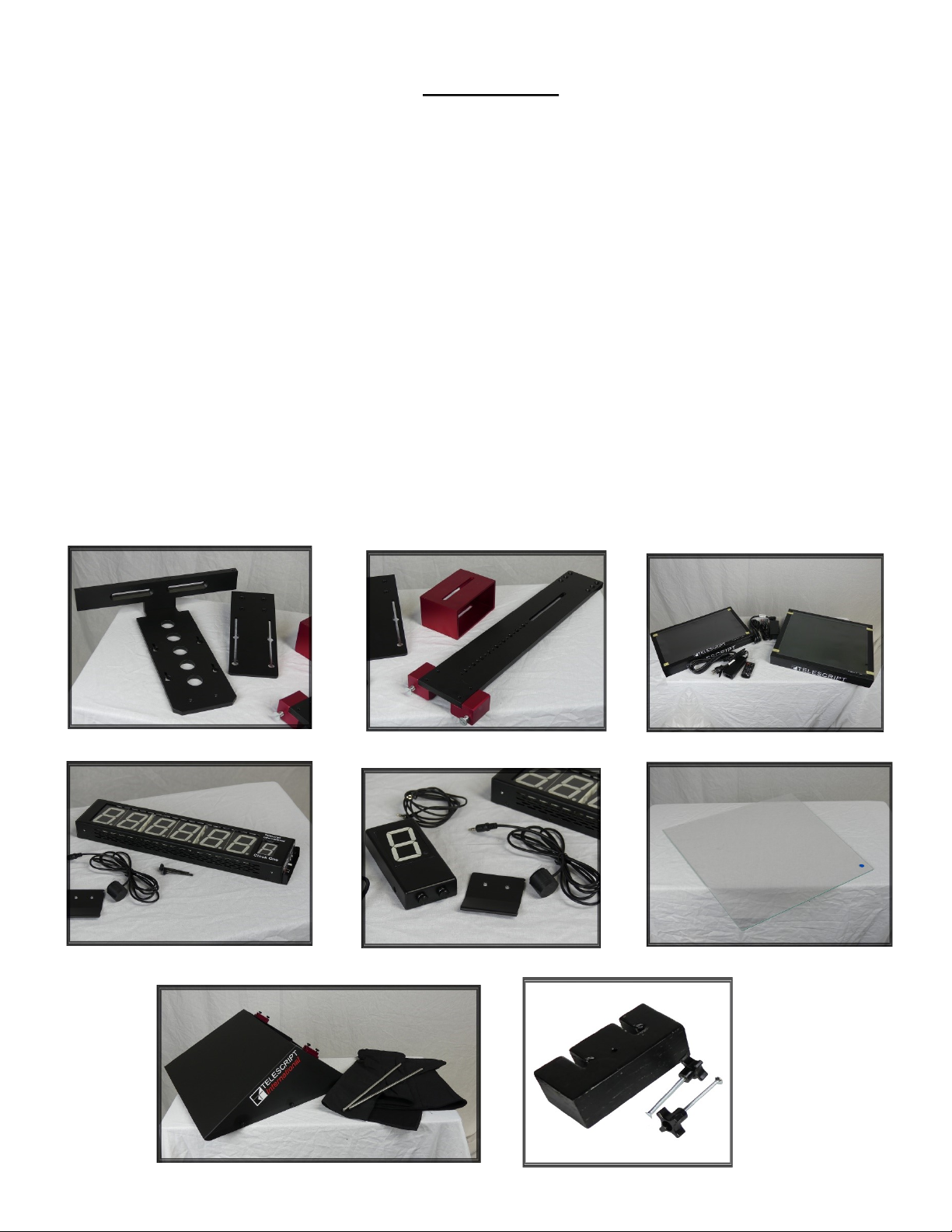
1. Remove the camera heads wedge plate from the cam-
era head and attach to the bottom of the 23” mount-
ing plate. Depending on the type of camera you are
using, you will need to make sure that you position
this plate in a location that brings the balance of the
system to the center. It may take more than one at-
tempt to get this position correct. Make sure you
mount the wedge plate on the bottom of the mount-
ing plate which has the recessed groove. This groove is
needed to attach your camera specific quick release
plate, or a box camera.
2. Now attach the mounting plate to the tripod head and
secure it in place.
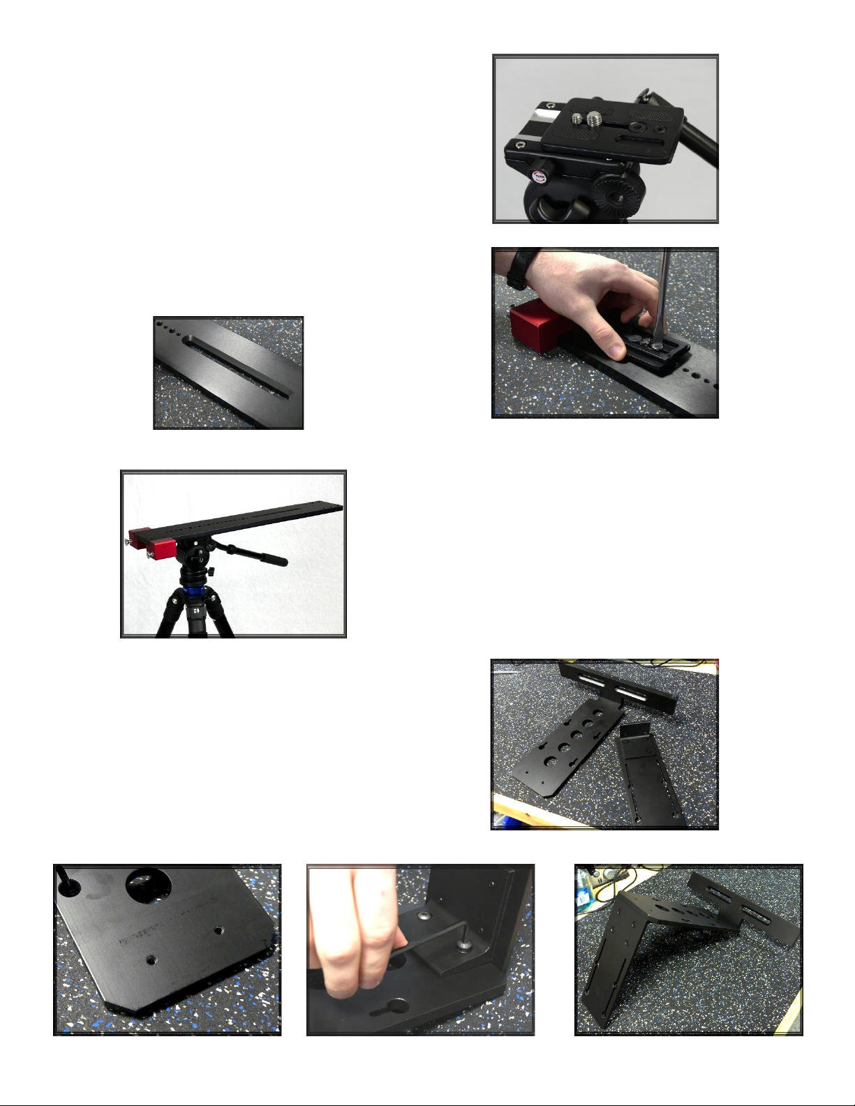
3. Now connect the prompter monitor mounting plate
and the reference monitor mounting plate. To do this,
use the two bolts that should have shipped installed at
the bottom of the prompter monitor mounting plate.
Sit the reference monitor mounting plate over the two
threaded holes on the bottom of the prompter moni-
tor mounting plate and attach using the two bolts.

4. Remove the two bolts that were shipped
installed on the front of your 23” mounting
plate. Then, use those two bolts to attach the
monitor mounting plate you assembled in
step 3. Be sure to center the monitor plate on
the 23” plate.
6. Take the two silver hood rods and insert them into the red holding
blocks on the back side of the trapezoidal hood. These two rods then
slide into the two holes on either side of the monitor back bracket. You
may need to loosen the two small thumb screws in order to slide the
rods completely into the holes. Tighten to secure.
5. If your camera requires to be raised, you can now mount the 3” riser
block by using the mounting bolts provided. Be sure to use two bolts
when mounting to prevent the block from swiveling. Then mount ei-
ther the cameras quick release plate, or the camera itself, to the top of
the riser block using the bolts provided. See the photo for an example.
Note: Each camera/lens setup has different height requirements. If you
need to raise the prompter rig for any reason, you can remove the two red
pillar blocks and flip them to the top side of the 23” mounting plate.
Note: It may be easier to secure one rod first, instead of try-
ing to insert both simultaneously.
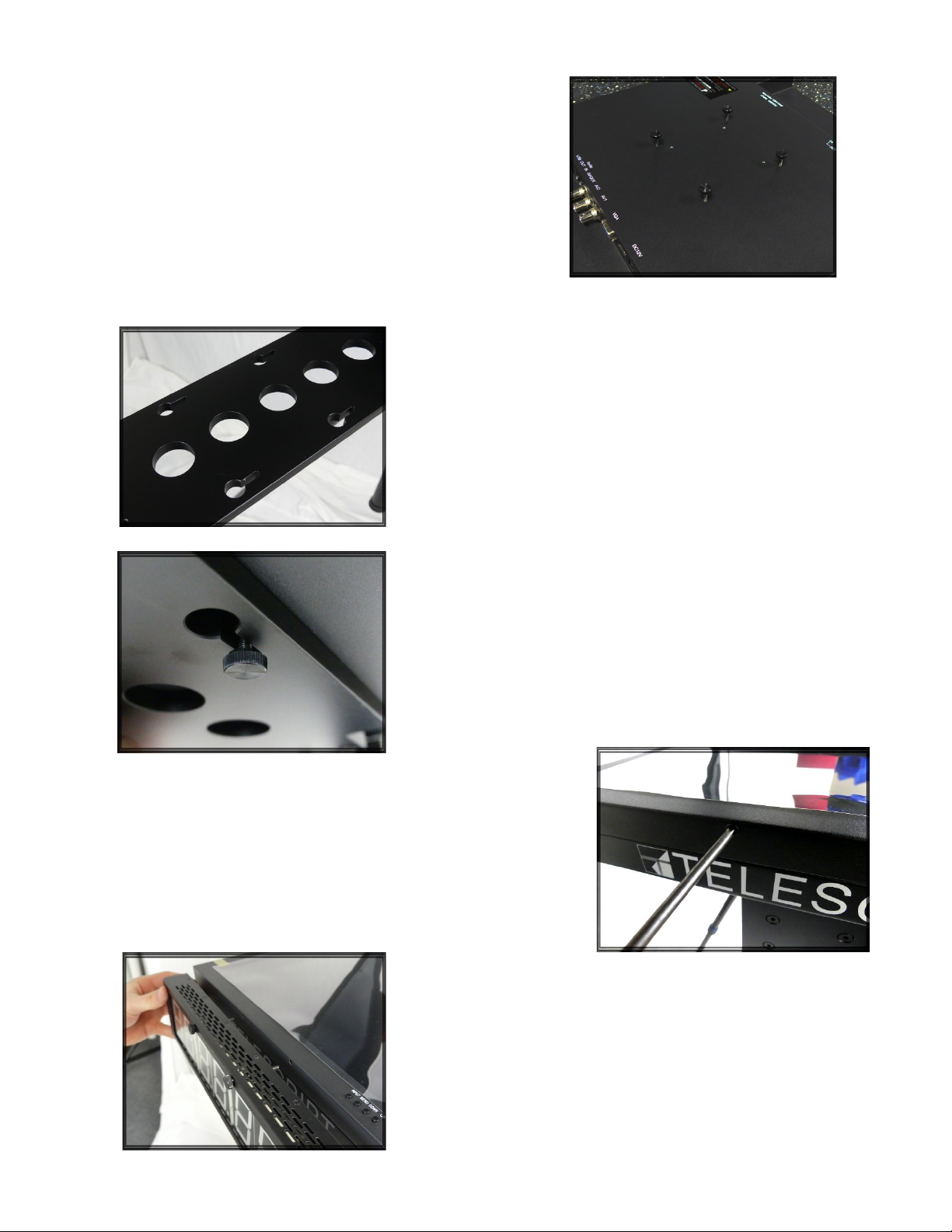
7. Take the 4 thumb screws for each monitor (the prompter
monitor and the reference monitor) and thread them one turn
into the back of each monitor. Be sure to not mix the screws up
as they are specific to each monitor. For the prompter monitor,
use the outer 4 holes. For the reference monitor, use the inner
holes.
8. On both the prompter monitor plate and the reference
monitor plate, you will find keyholes that correspond with
the thumb screws on the back of each monitor. First take
your prompter monitor and sit in inside the keyholes. Then
slide the monitor back as far as the keyhole will allow and
tighten to secure the monitor.
9. If your prompter monitor still has the two phillips head screws in
it, remove them now.
10. Take the two long thumbscrews and insert them
through the two holes along the top center of the ClockOne.
Thread them into the two corresponding holes on the face
of the prompter monitor Tighten to secure.
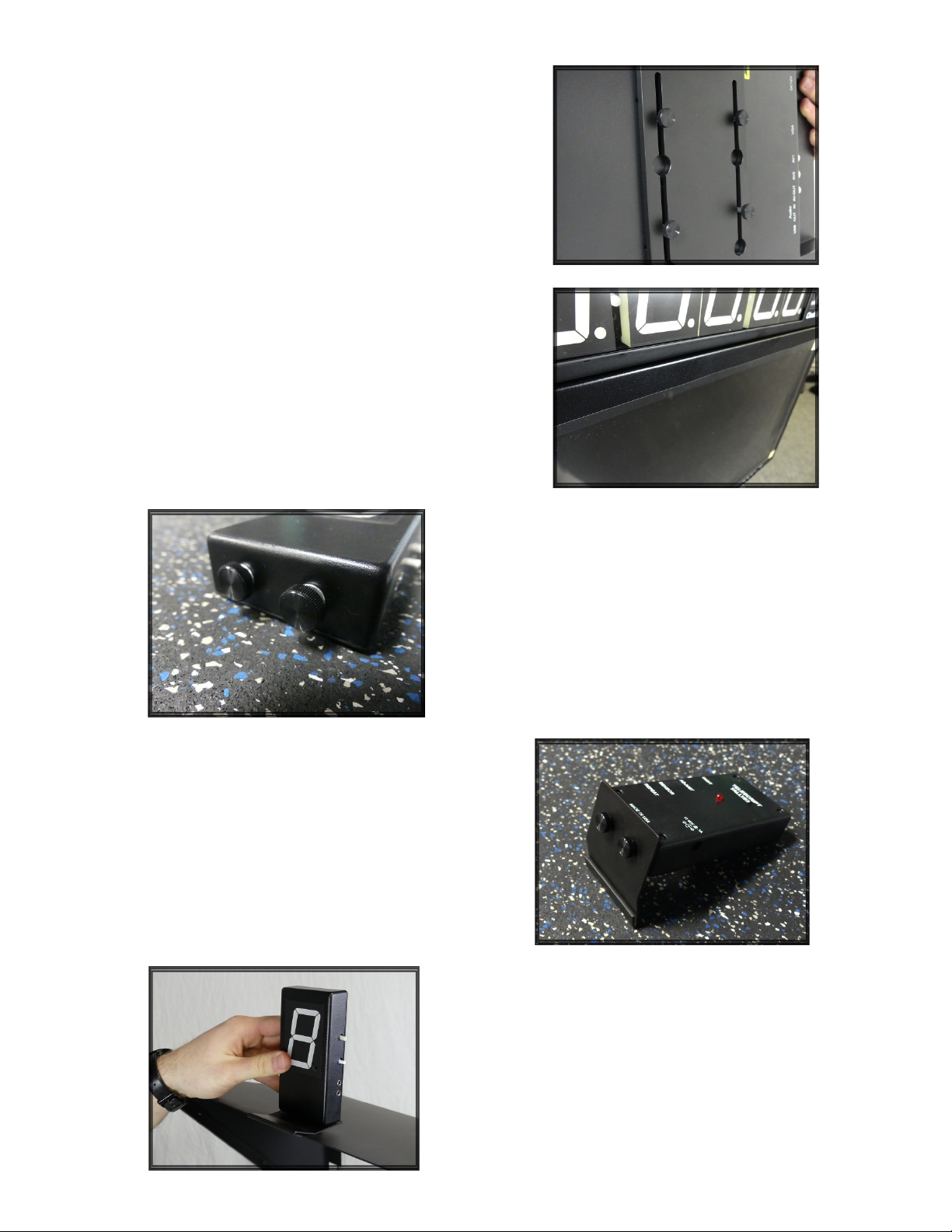
12. On the bottom of your TallyOne you will find 2
thumb screws. Remove them from the tally.
13. Attach the TallyOne to the tally mounting plate as shown
in the photo. Be sure that the J-Hook edge of the plate is fac-
ing the front side of the tally and is curving upward.
11. Take your reference monitor and insert the thumb
screws into the corresponding keyholes on the reference
monitor mounting plate. Slide the monitor up until it sits
flush with the ClockOne.
14. Now clip the TallyOne to the center of the top edge of
the trapezoidal hood by sliding the edge of the hood into
the J-Hook on the front of the tally mounting plate.

15. Along the bottom inside edge of the hood mask, you will find a strip of Velcro just above the bottom flap of
the mask. Attach this strip Velcro on the mask to the Velcro strip along the bottom of the beamsplitter frame. Tuck
the bottom flap of the mask behind the prompter monitor to conceal the mounting hardware.
16. Now start attaching the rest of the mask to the hood by using the Velcro
strips on both the mask and the inside edges of the hood. Be sure to make a
tight bond between the two to ensure no light leaks through the edges.
17. Remove the top two thumb screws on both sides of the
hood. Then, tilt the beamsplitter frame down and slide the
beamsplitter into the frame. Be sure that the reflective side of the
glass is facing outward. The reflective side has a small sticker in
one of the corners. Once you have slid the glass properly into the
frame, tilt the frame back up and reinsert the thumb screws into
the beamsplitter frame to secure the glass in place.

18. If your system requires additional backweight in order to
get the system to balance on your head properly, attach the
15lb counterweight provided. Take the two hanger bolts and
insert them into the holes at the back edge of the 23” mount-
ing plate. Then, slide the counterweight on to those bolts.
Tighten the 4-point knobs to secure the weight. You may need
to use a flathead screwdriver to hold the bolt in place while
turning the knobs as they may spin as you tighten.
19. Power all accessories using the power supplies
provided. Connect the tally light sensor to the SEN-
SOR port on the side of the TallyOne. You may also
use a custom tally cable that can send the tally sig-
nal out of the camera to the TallyOne (not provided
by Telescript).
Use the tally repeater cable (stereo cable) provided
to loop the sensor signal out of the tally into the
SENSOR port on the side of the ClockOne.
Your ClockOne will display time of day when pow-
ered up. You can display TimeCode or a countup/
countdown by using the LTC port on the side of the
unit. See the Clock and Tally section for further de-
tails on using the clock and tally.
If you require all units to be powered off on ONE
power supply, you will need to contact Telescript
International to obtain a special order power supply
and power adapter.

20. Your fully built Expert System should now look like
this when powered and with signals being sent to both
monitors.
ClockOne and TallyOne Operation
TallyOne:
The TallyOne uses a DC power input jack that accepts a standard 2.1mm plug, with center positive. Input power is
nominally 12VDC at 1.2 amps maximum .
Connect the provided light sensor to the Sensor input on the tally. Then place the sensor end over the tally light on
your camera. Make sure all light is completely blocked out from the sensor or else the sensor will have difficulty
sensing light changes on the camera tally. Use the ADJUST dial on the side of the tally to adjust the sensors sensitivity
to light. Turn the DIGIT dial to change the number displayed on the front of the tally.
Connect the provided 3.5mm cable to the Repeat input and plug it into the Sensor input on the Clock One. The Re-
peat 3.5mm jack provides a contact closure to ground when digit display is red. This output can be used to drive the
sensor input on another device such as a ClockOne or another TallyOne allowing daisy chaining of multiple devices
from a single optical sensor or contact closure source
The red light on the rear of the tally will illuminate when the cameras tally is lit.
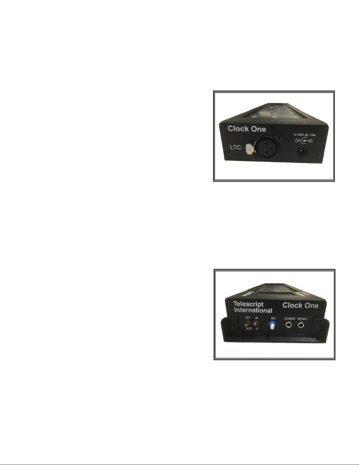
ClockOne Right side:
The Sensor 3.5mm jack accepts an optical sensor or contact
closure to ground. Low illumination or open contact condition
displays green digits.
High illumination (such as when a tally light is on) or a closed
input contact (such as from another clock or tally digit) causes the
display digits to turn red.
The ADJ dial adjusts the sensitivity of the light sensor.
Like the TallyOne, the Repeat 3.5mm jack provides a contact clo-
sure to ground when digit display is red. This output can be used
to drive the sensor input on another device such as a Digit Tally
or another clock, allowing daisy chaining of multiple devices from
a single optical sensor or contact closure source.
Time of day can be set by pushing the SET lever toward you. Once
the clock digit blinks, you can now change that digit by pushing
the lever in the opposite direction. Once your digit is set, pull the
lever toward you again to move to the next set of digits. Repeat
the process until your clock is set.
ClockOne Left side:
LTC (Longitudinal Time Code) input is a standard XLR3 female
that accepts a balanced or unbalanced signal between 50 mV
and 2 Vpp. Pin 1 is ground, a balanced signal is applied between
pins 2 and 3, and an unbalanced signal may be applied between
either pin 2 or pin 3 and ground.
The DC power input jack accepts a standard 2.1mm plug, with
center positive. Input power is nominally 12VDC at 1.2 amps
maximum.
ClockOne:
Note: If you are daisy chaining together a clock and a tally, the sensitivity of the light sensor is controlled by the unit that has
the sensor device connected to it. All secondary devices are slaves to the first device.
If you are attempting to custom wire a cable to trigger the tally, instead of using
the provided light sensor, the following technical information below will be help-
ful in wiring your cable.
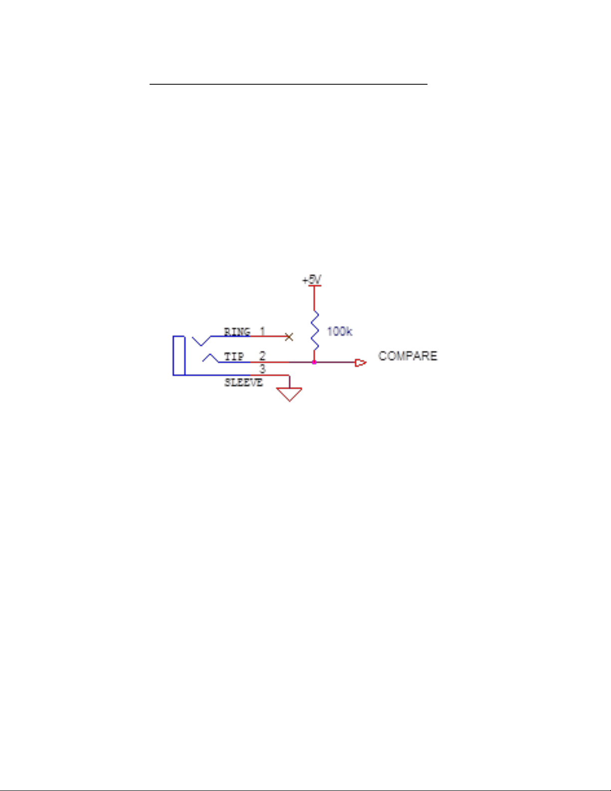
For older Telescript TallyOne units (only Red/Green units), or if your tally system
only outputs On/Off (Red/Green), follow these notes:
The sensor input is a standard 3.5mm phone jack. The sleeve is grounded. The tip
is pulled up to +5 volts by a resistor. The ring is not connected, therefore it does
not matter whether the mating plug is a mono or stereo type. The voltage at the
tip is compared with the setting of the threshold potentiometer between approxi-
mately 0.7 and 4.3 volts. If the tip connection is open or the voltage is above the
threshold setting, the display will be green. If the tip connection is pulled below
the threshold setting or shorted to ground, the display will be red. The tip con-
nection can be driven by a switch or relay contact to ground, a light dependent
resistor to ground, a logic level, or other means.
Each clock or tally has an associated 3.5mm output jack labeled “repeat”. When
the display is green, the output is open circuit. When the display is red, it offers a
Custom Wiring for the ClockOne and TallyOne
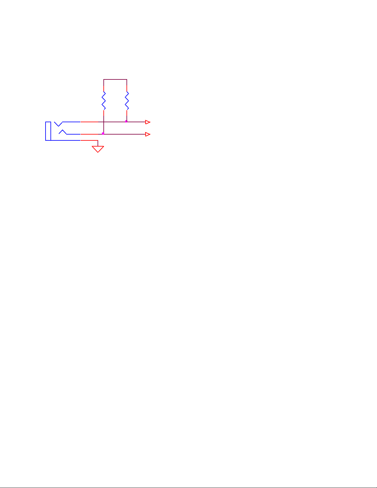
For newer Telescript Tally One units (Red/Amber/Green), and if your tally system outputs a
“Standby” or “Ready” signal, the following technical information explains the interface.
The sensor input is a standard 3.5mm stereo phone jack. The sleeve is grounded and the tip
and ring are each pulled up to +5 volts by resistors. The voltages at the command inputs are
compared with the setting of the threshold potentiometer located on the side of the tally. This
can be set anywhere between approximately 0.7 and 4.3 volts. Command signals can be sim-
ple contact closures to ground, or a variable resistance such as a light dependent resistor, or a
logic signal. If logic signals are used, a swing of at least 2V is recommended. The tally can tol-
erate swings as high as +/- 12V.
The command inputs are active low, therefore an open circuit or high logic level is ignored.
The tally responds to the four possible command combinations as follows:
TIP = H, RING = H displays green
TIP = H, RING = L displays amber
TIP = L, RING = H displays red
TIP = L, RING = L displays red
Each tally has an associated 3.5mm output jack labeled “REPEAT”. When the display is green,
the output lines are open circuit. When the display is amber or red, the associated line offers a
low impedance path to ground. The repeat output can be used to daisy chain devices for con-
trol from a single input. Note that devices which do not support amber do not repeat the am-
ber signal. In such instances, the tally should be the first device in the daisy chain.
SLEEVE
100K 100K
RING
TIP RED COMMAND
1
2
3
+5V
AMBER COMMAND
This manual suits for next models
3
Table of contents
Other Telescript Professional Video Accessories manuals


