Telescript ROBO210R-SDI User manual

258 Oak Tree Road, Tappan, NY 10983
Telescript’s PTZ
Prompting System
ROBO210R-SDI
Assembly Instructions
telescript.com
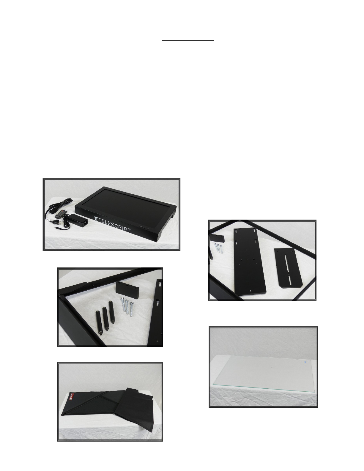
Parts List:
1 - 21.5” Telescript 16x9 Prompter Monitor
1 - Power Supply w/ Remote
1 - Hood
1 - Hood Mask
1 - Monitor Mounting Plate
1 - Camera Mounting Plate
1 - Frame Riser
3 - 1/4-20 x 2-3/8 Flathead Bolts
3 - Camera Riser Poles
1 - Back Bracket w/ Beamsplitter Frame
2 - 14-20 x 1 Hex Bolts w/wingnut
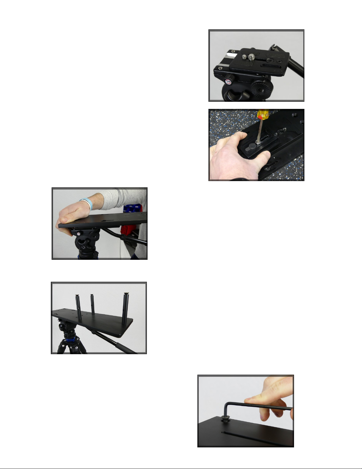
1. Remove the camera heads wedge plate from the cam-
era head and attach to the bottom of the monitor
mounting plate. Depending on the type of camera you
are using, you will need to make sure that you position
this plate in a location that brings the balance of the
system to the center. It may take more than one at-
tempt to get this position correct.
Note: If you are not using a head with your tripod, you can
screw the monitor plate directly to a tripod that has a 3/8
threaded bolt on top.
2. Now attach the monitor plate to the tripod head and
secure it in place.
3. Screw the three camera plate posts into the three
threaded holes in the monitor plate. You can use the hole
in the post to insert a screwdriver through to tighten if
necessary.
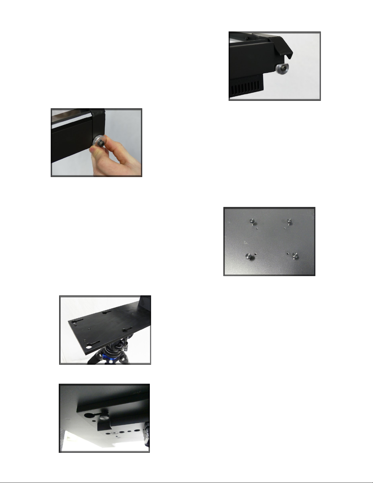
4. Remove the three allen bolts from the top of
the posts. Place the camera plate on top of the
posts and align the posts with the corresponding
holes. Make sure the side with the recessed holes
are face up before you insert and tighten the allen
bolts.
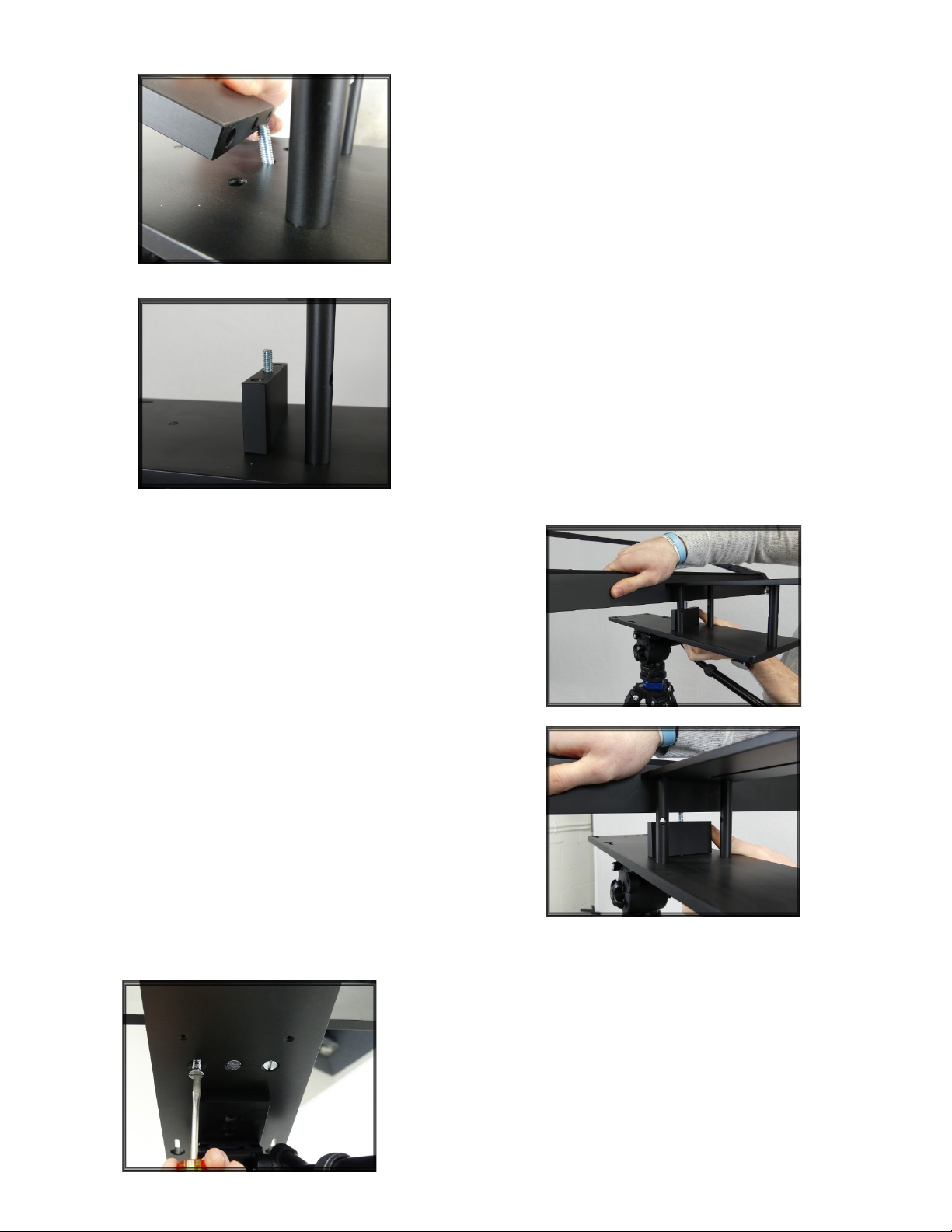
5. On the bottom of the monitor plate you will
see three equidistant, recessed holes. Insert
one of the three 1/4-20 x 2 3/8 bolts through
the center bottom of the monitor plate. Slide
the frame riser over the top of the bolt.
Note: If completing these steps becomes difficult,
having a second person, or bringing the hardware to
a workbench will help make it easier.
6. Thread the bolt into the center threaded hole on
the bottom of the back bracket (which is attached to
the beamsplitter frame) and hand tighten.
7. Thread the remaining two bolts through the
bottom of the monitor plate and tighten using a
flathead screwdriver. Do not fully tighten until all
three are threaded into the bracket holes.
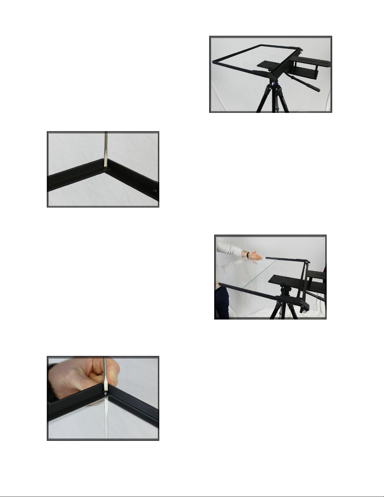
8. Your assembled hardware should now look like
the photo on the right.
9. The top rail of the beamsplitter frame has two
small flathead screws holding the rail to the frame.
Remove both screws and remove the top
beamsplitter rail.
10. Slide the beamsplitter glass into the beamsplitter
frame. Be sure that the reflective side of the glass is
facing down in this step. The reflective side of the
glass has a round sticker in one of the corners.
11. Reattach the top rail of the beamsplitter frame
and attach with the same small screws you removed
earlier. Be sure to not overtighten.
14. Partially thread the four monitor screws into the
outer threaded holes on the bottom of the monitor.
15. On the monitor plate you will see four keyholes.
Guide the thumb screws in the bottom of the
monitor into these keyholes and slide the monitor
back as far as you can. Tighten the thumbscrews.
Note: Be sure you have your monitor facing the proper
direction. The edge of the monitor with the Telescript
logo is the front of the monitor and should be facing you.
12. Turn the two silver dials on the rear of the backbracket
so the flat side is facing upwards.
13. Lift the beamsplitter frame up until it is in it’s most upright
position and turn the dial until it is tight against the beamsplitter
frame.
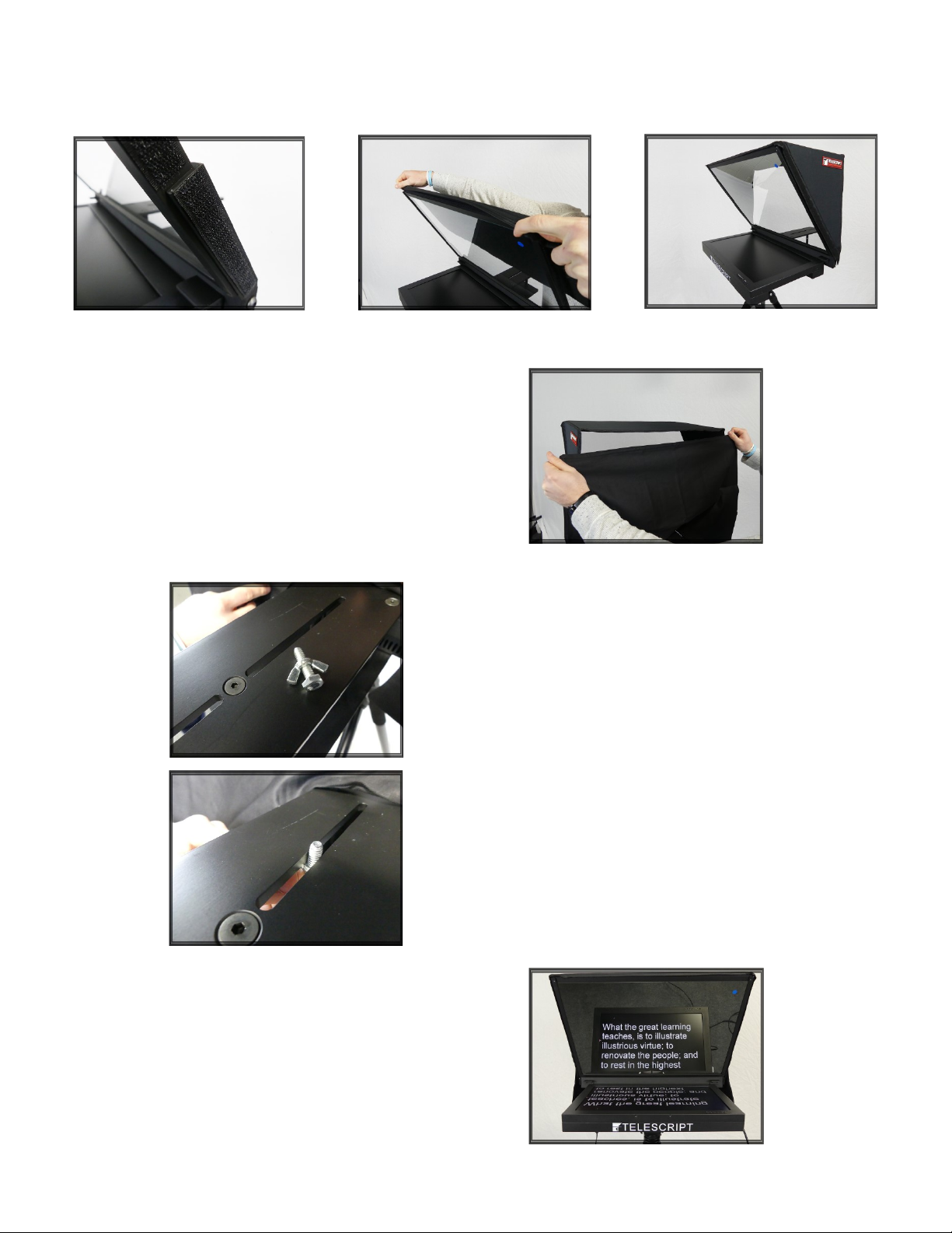
16. The beamsplitter frame has Velcro along the sides.
Attach the hood to the frame using these Velcro strips.
17. Take your hood shroud and attach it to the back of
the hood using the Velcro on the edges of the hood
and shroud.
18. Your camera now can mount on top of the camera
plate behind the beamsplitter using either your camera
manufacturers mounting plate, or by using the provided
1/4-20 bolt with wingnut that was sent with your system.
Depending on the type of camera, position the lens as
close to the beamsplitter as you can (without touching
the glass). Cover the camera with the hood shroud.
19. This is what your system should now look like.

Accessories
If you’ve purchased your ROBO210R-SDI system with a ClockOne or TallyOne, mounting is very
easy. To mount your ClockOne, simply remove the two Philips head screws on the front of the
monitor (Photo A). Then insert the two long bolts provided with your clock through the holes at
the top center of the clock. Then thread the bolts into the two holes on the face of the monitor
until tight. (Photo B).
PHOTO A PHOTO B
If you’ve purchased a TallyOne, your top rail of the beamsplitter frame will hve two threaded holes
in it (Photo C). Simply attach the provided tally bracket (Photo D), and then attach the tally to the
bracket (Photo E).
PHOTO C PHOTO D
PHOTO E
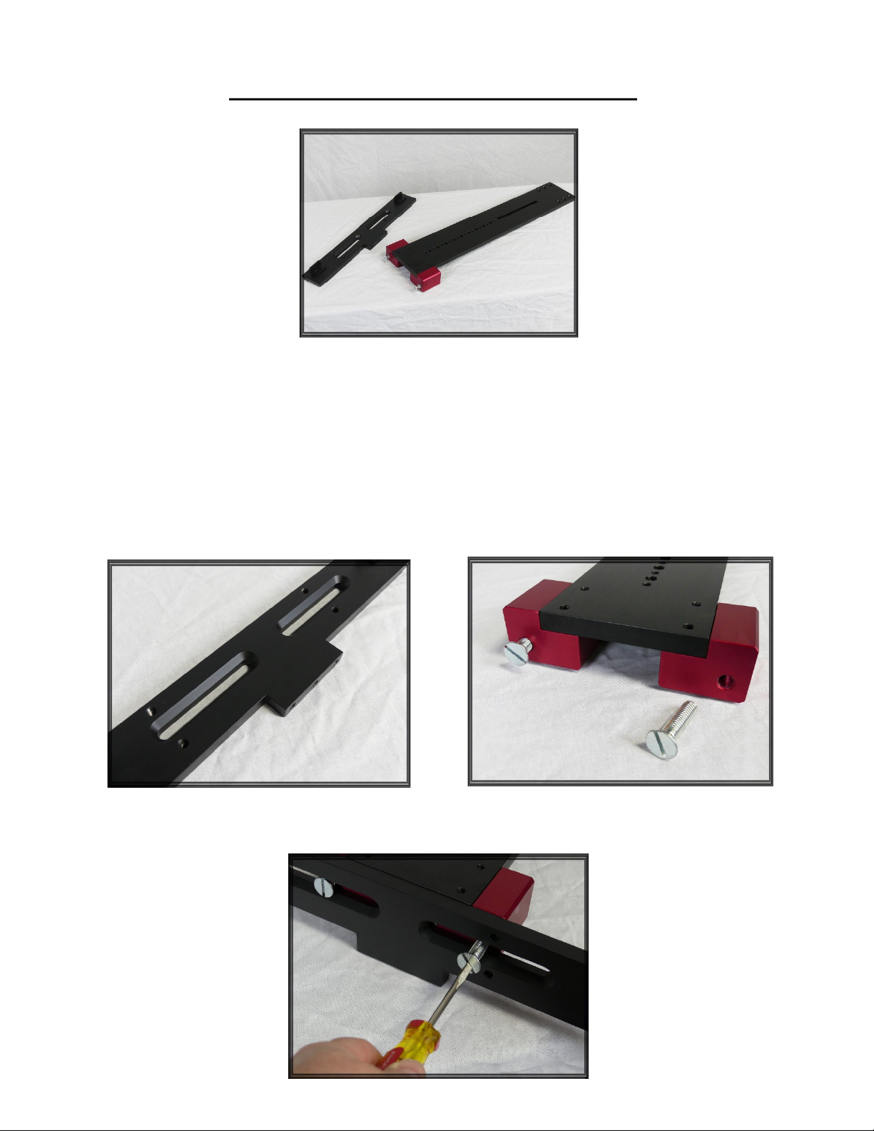
Studio Mount (23” Plate)
If you’ve purchased a ROBO210R-SDI system with a studio mount configuration, your hardware may
be slightly different from what you see in this manual. Most steps still apply, however, since you
have a 23” mounting plate, your mounting process is different. Your back bracket will have either
recessed grooves or recessed holes (Photo A). Using the bolts from the 23” plate (Photo B) attach
the 23” plate to the back bracket first, before assembling the rest of the hardware (Photo C)
PHOTO A PHOTO B
PHOTO C
Table of contents
Other Telescript Professional Video Accessories manuals


