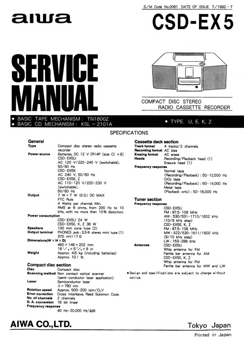
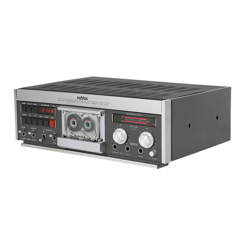
Teleton C-500 User manual

F
SERVICE
MANUAL
Stereo
Cassette
Deck
MODELS
C-500
C-500BS
iw)
Teleton
TELETON
Elektro
GmbH.
Oberhausener
Str.
17
4000
Ddsseldorf-Rath
Tel:
(0211)
65
30
81
TX:
858
6768
Germany:
TELETON
ELECTRO
(UK)
Co.,
Ltd.
Somerton
Works,
Prince
Avenue,
Westcliff-on-sea,
Essex
SSO
OHU
Tel:
(0702)
337681
TX:
99338
United
Kingdom:
TELETON
N.V.
2200
Borgerhout
Belgium
Prins-Leopold-Straat
28
Tel:
03/361045
TX:
32508
03/357670
Belgium:
France:
TELETON
Electro
(France)
S.a.r.l.
21
rue
Paul
Lafargue
94270
Le
Kremlin-Bicétre
Tel:
677
6934
TX:
24
468
ALLELECTRIC
AG.
Gartenstrasse
12-5600
Lenzburg
Tel:
064/516951
TX:
68208
Switzerland:
Specifications
are
subject
to
change
without
notice.
SPECIFICATIONS
aT
VD
Cincia
enteuuerl
ecosuicon
tina
nt
sa:
C500,
C500BS
Power
Source...................
AC
240V,
50
Hz
(UK)
AC
110/220V,
50
Hz
(Continent)
Power
Consumption..........
AC
12W
Dimensions.................00008
420
(W)
x
150
(H)
x
250
(D)
mm
MY
IGE
spots
serehssiundckxarseeanns
6.5
kg
CASSETEC
cccccciiiceeccice
ravine
wnwes
C-30, C-60,
C-90
Tape
Speed
.............0...00.
4.76
cm/sec
Fast
Forward
Time............
Less
than
90
sec
(with
C-60)
Rewind
Time................008.
Less
than
90
sec
(with
C-60)
Recording
Time
................
90
min.
(with
C-90)
Recording
System.............
AC
bias,
85
kHz
Erasing
System.................
AC
erasing
Terminals:
TPL
UN
cys
avai
diddaanitscccmnes
50
mV
(50
kQ2)
L-MIC-R,
PB/REC
(DIN)..
0.7
mV
(10
kQ)
LINE
QUIT
picnciccasmgadsvecuss
580
mV
PHONES
oooceccccccccesceseeee
>
mvien
oe
oe
Pe
MTT-150
PBJREC
{OUN)iccaai
savannas
580
mV
Wow
and
Flutter
..............
Less
than
0.095%
WRMS
Signal-To-Noise
Ratio
.......
46
dB
(Normal)
46
dB
(CrOs)
|
eee
nee
Dolby
Effect
...cccisciciteosnsaces
8
dB
Frequency
Response
.........
40
~
12,500
Hz
(Normal)
40
~
14,000
Hz
(CrO2)
Distortion
..........ccccece
eee
eee
2.8%
(Normal)
3%
(CrO,)
Subfunctions:
Tape
Select
Switch.........
CrO2/FeCr/NORM
Dolly
NE
vicactvciceadss
hound
DOLBY
NR
(ON/OFF)
Input
Select.....0.0000000.0..
MIC
(CIN)/LINE
IN
Red
LED
Dolby
NR
Indicator
Red
LED
Recording
Indicator
3-digit
Tape
Counter
Semiconductors:
Transistors
.....00...00.ccce
14
esa
ack
dace
aden
eremaud
Rvennabens
2
DBCS
oid
cj
ewe
xs
xeneted
heed
sdin
8
+
1
stacked
diode
EOS
segs
ncwandameriadiam
ovies
3

PARTS
IDENTIFICATION
@)
24)
@3@2)
@
@
19)
13)
®@O®
OOD
®
QO
OY
YO
YO
ac
voltage
Model
C500
only
1.
Power
Switch
16.
Input
Select
Switch
2.
Eject
Lever
17.
Recording
Level
Control
3.
Record
Lever
18.
Peak
Level
Indicator
4.
Rewind
Lever
19.
VU
Meters
5.
Play
Lever
20.
Counter
Reset
Button
6.
Fast
Forward
Lever
21.
Tape
Counter
7.
Stop
Lever
22.
Recording
Indicator
8.
Pause
Lever
23.
Dolby
Noise
Reduction
Indicator
9.
CrO.
Tape
Switch
24.
Cassette
Room
Lamp
10.
Microphone
Jacks
25.
Cassette
Door
11.
Ferri-Chrome
Tape
Switch
26.
LINE
OUT
Jacks
12.
Normal
Tape
Switch
27.
DIN
Jack
13.
Headphone
Jack
28.
LINE
IN
Jacks
14.
Dolby*
Noise
Reduction
Switch
29.
AC
Voltage
Select
Switch
(Model
C500
only)
15.
Output
Level
Control
*Dolby
is
a
trademark
of
Dolby
Laboratories.

MOTHER
P.C.
BOARD
RY
(BL
GRY
(RED
UC
L
|
S06
GRY
(BLU
LED
P.C.
CIRCUIT
BOARD
(A)
GRN
to
primary
P.C.B.
RED
to
primary
P.C.B.
Anode
tetminal
(with
longer
lead)
000000000
TOMTTIN)
‘
z
Pe
Ss
POWER\
head
Y
i
nne
tor
4)(
ie
Erase
La,
>
Connector!
KGRY)
PB/REC
r
MU?
Sw(b}
MUT
SWAR
BLK
to
primary
PCB.
Mount
the
LED
as
shown
in
the
figure
below.
+O
(G5
~95
LED
==
LED
P.C.
CIRCUIT
BOARD
(B)
GRY
(GRN)
GEN
ORN
to
primary
P.C.B.
Anode
terminal
(with
longer
lead)
eee
/NE
OU
(2)
nw
NW
~
XSe
oSt
aca
wag
XS
LIME
OUT
0
FS
>
ie.
xy
(&)
x
8
SS
RS
a
<
~
ee
se.
S83
ve
8
Ss
2
*&
S
§
&
SS
we
WHF
Bik
d d
3
BRM
Bz}
A
«t.
ven
FE]
a
REC
LEVELR
TPUT
LEVEL
BRN
(BLK)
BRN(RED)
MIC
R
Y
BLU
to
primary
{Gn
P.C.B.
Mount
the
LED
as
shown
in
the
figure
below.
+
Note
:
LED
)
t.
Four
&
marks
indicate
the
bridged
position
where
playback
frequency
characteristics
are
adjusted.
2
The
position
marked
with
&
should
be
bridged
after
a
ie
te
74,
the
recording
current
adjustment.
3
—-wt
means
that
a
silicon
glass
tube
is
inserted
“NIN
@
resistor

SCHEMATIC
DIAGRAM
S-7
Lie
iNn(O)
TOTO
se
!
|
G03
2SC/74O
LIARS
|
asv
eo
220
av
ie
EME)
KuslS
y20y
;
|
|
|
|
|
lay?
Jo
IZ\
|
|
|
|
|
rete
ee
oe
oe
12.2v
23
/00K
B
,
C36
220P
REC/PB
EHD
pli
(0)
prccco
a
os
ye
ti
2
SDs0/
L/NE
/N
C139
0.01
R
CH
C502
220ufe.3
-
!
5
wa"
©)
we
our
|
&
[satay
eee
8,
os
4
=
Su
Sua,
Sor~Syo9
—
REC/PB
SW
(PB
POSITON)
:
Spry
Si-2
FWD
SW.
(OFF
POSITION)
See
I
Se
sig
TAPE
SELECT
Sw.
(Normal
POEITION)
Og-)
,
Sg-2
POWER
SW.
(OFF
POSITION
)
*
Voltage
level
when
the
REC/PB
Switch
1S
set
to
REC.
(At
two
points
Sieh
y
DISS
DOLBY
Sw.
(OFF
POSITION)
on
the
diagram)
| |
Sy
VOLTAGE
SELECTOR
SW
(//0~120V.
POSITION)
&X
Voltage
level
when
the
DOLBY
swith
1s
Set
to
ON.(At
one
point
on
Sees
TAPE
SELECT
SW.
CrO2(Normal
PCS!
TION)
the
diagram)
|
|
|
Ge
Sc
TAPE
SELECT
SW.
FeCr(
a
)
(Use
q
tester
having
no
internal
impedance.)
Over
LINE/MIC
SW.
(LINE
POSITION)
PAE
:
Printed
yvesistor

PARTS
LIST
NOTE:
Standard
Parts
as
Resistors,
Capacitors,
etc.,
not
listed
here.
102
141
142
144
145
146
148
149
150
151
152
153
154
156
157
157
158
158
159
160
160
161
161
165
165
167
168
169
170
171
172
173
175
176
176
177
178
181
182
183
184
185
186
187
188
189
190
191
192
193
194
195
196
197
198
199
201
211
213
218
221
222
CABINET
AND
CHASSIS
KGEO12822
KGC98447
KGE3135
KGE98674
KGE49353
KGE42470
KGE42363
KGE42498
KGE42500
KGE98473
KGEO13073
KGE100447
KGE100480
KGE99708
KGE012733
KGE0O13070
KGE44428
KGE44496
KGE100612
KGE98767
KGE100519
KGE99864
KGE100487
KGE47154
KGE47140
KGD98521
KGE35033
KGE98565
KGE42521
KGE100448
KGE99478
KGD99482
KGC98465
KGC100454
KGC
100482
KGE46482
KGE99431
KGE42471
KGE42472
KGE97423
KGE20644
KGE20643
KGC98450
KGC99491
KGE43158
KGC98441
KGE99282
KGE0O13063
KGE100451
KGE100446
KGE100452
KGE99606
KGE49354
KGE42269
KGE100523
KGE100609
KGE13599
19030
19026
22138
KGE13600
19077
Wire
Clamp
Cover
Cushion,
10
x
30
x
6
Washer,
12¢
x
5.2¢
x
O.5t
Jack
Plate
Ass’y
Slide
Switch
Connector
3P
Slide
Switch
Multi
Switch
Slide
Plate
Mother
Board
Ass’y
Push
Button
(B)
Name
Plate
(UK
only)
Nylon
Rivet
Power
Cord
Ass’y
(continent
only)
Power
cord
Ass’y
(UK
only)
Power
Cord
(Continent
only)
Power
Cord
(UK
only)
Important
Label
(UK
only)
Mounting
Plate
(continent
only)
Mounting
Plate
(UK
only)
Cord
Bush
(Continent
only)
Cord
Bush
(UK
only)
Power
Transformer
(Continent
only)
Power
Transformer
(UK
only)
Transformer
Mounting
Plate
Spark
Killer
Cover
Power
Switch
Push
Button
(A)
Mounting
Plate
Chassis
(Left)
Chassis
(Centre)
Rear
Panel
(Continent
only)
Rear
Panel
(UK
only)
Diode
(LED
Red)
LED
P.C.
Board
(B)
Mic
Jack
Headphone
Jack
LED
P.C.
Board
(A)
Variable
Resistor
Variable
Resistor
Chassis
(Right)
Chassis
(Front)
Meter
Bottom
Cover
Foot
Front
Panel
Assy
Knob
Knob
(R)
Knob
(L)
Cover
Binding
Band
Slide
Switch
(Continent
only)
Insulation
Board
(Continent
only)
Cover
Screw,
M2.5
x
5
Screw
with
Spring
Washer,
M2.6
x
4
Screw
with
Spring
Washer,
M2.6
x
5
Flat
Washer,
2.3¢
x
6¢
x
0.4t
Screw,
M2.5
x
8
Screw
with
Spring
Washer,
M2
x
6
232
233
234
235
236
239
240
241
243
244
246
248
249
NO
OP
WND
—
15
16
17
18
19
20
28
29
30
31
32
33
34
35
36
37
38
39
40
41
42
43
44
45
46
47
48
49
50
51
52
53
54
55
61
62
19014
13052
KGE98861
KGE98043
19063
18092
19015
KGE98288
19045
18057
19113
KGE98081
14706
KGE99115
KGE98861
KGEO11264
KGEO12431
KGE97774
KGE97738
KGEO12822
KGE14112
KGEO10656
KGE99135
KGE98836
KGE98833
KGE97797
KGEO10775
KGE010783
KGE13446
KGE010774
KGE010749
KGE010748
KGE9992
KGE97868
KGE97860
KGDO10755
KGE96716
KGE14343
KGE99050
KGE9947
1
KGE99052
KGEO11221
KGE97735
KGE97733
KGE97734
KGD97736
KGEO11220
KGEO11627
KGE7484
KGE13754
KGE97938
KGE99734
KGE42561
KGE14760
KGEO11890
KGE97740
KGE97731
KGE47022
KGE95134
KGE99457
Description
Screw
with
Spring
Washer,
M2.6
x
6
Tapping
Screw,
M2.6
x
6
Screw,
M2.5
x
4
Binding
screw,
M3
x
5
(BLK)
Screw
with
Spring
Washer,
M4
x
10
Nut,
M4
Screw
with
Knurled
Flange,
M3
x
5
Square
Washer
Screw
with
Spring
Washer
M2.6
x
6
Nut,
M2
Screw
with
Spring
Washer,
M2
x
5
Screw,
M2.5
x
6
Screw,
M5
x
8
(BKL)
Screw,
M3.5
x
5
(BLK)
Screw,
M2.5
x
4
MECHANISM
Plate
Ass’y
Lever
Ass‘y
Roller
Flywheel
Bracket
Wire
Clamp
Thrust
Adjusting
Screw
Flywheel
Ass’y
Flat
Belt
Twist
Coil
spring
Lock
Plate
Link
Stop
Arm
Ass’y
Function
Plate
Assy
Tension
Coil
Spring
Button
Lock
Plate
Pressure
Ass’y
Tension
Arm
Ass’y
Pause
Lever
Ass’y
Tension
Coil
Spring
Tension
Coil
Spring
Square
Belt
Auto
Shut-Off
Mechanism
Ass‘y
Washer
Thrust
Plate
Spring
Spring
Rec.
Lever
Tension
Coil
Spring
Tension
Coil
Spring
Ass‘y
FF
Plate
Play
Plate
Rew.
Plate
Rec.
Plate
Tension
Coil
Spring
Ass‘y
Idler
Ass‘y
Nylon
Washer
Idler
Spring
Idler
Spring
B
Switch
Mounting
Plate
Slide
Switch
Tension
Coil
Spring
Lock
Plate
Ass'y
Motor
Mounting
Plate
Motor
Pulley
Motor
G2NLO
Brake
Plate
Cassette
Holder
Spring

Hc
nc
MIR
9
65
66
67
68
69
70
71
72
73
74
75
76
77
78
79
80
81
82
83
84
85
86
87
88
89
90
91
92
93
94
95
96
97
98
99
100
101
102
103
105
106
107
108
109
110
111
112
113
114
115
116
117
122
123
124
125
126
128
129
131
201
202
203
KGE49347
KGE95644
KGC0O10747
KGE97826
KGE55072
KGD99452
KGEO12487
KGE95378
KGE99287
KGE99459
KGEO11222
KGE97939
KGEO10717
KGEO10779
KGE98406
KGE47138
KGE96998
KGE98357
KGEO10767
KGE97741
KGE3111
KGE14426
KGE97727
KGE97712
KGE98432
KGE99470
KGE99456
KGE97710
KGE98054
KGE97732
KGE97189
KGEO11614
KGE98310
KGE98846
KGE97715
KGDO10772
KGE47143
KGE97726
KGE3354
KGEO12822
KGE97804
KGE97932
KGD97799
KGC99448
KGEO12430
KGE98469
KGD99453
KGE99455
KGE99468
KGE99469
KGE99454
KGD99487
KGE99474
KGE97800
KGE99828
KGE97802
KGEO13061
KGE99464
KGE99458
KGD99486
KGD012317
KGE14605
KGE13599
22140
22135
Lamp
Lamp
Holder
(A)
Mechanism
Base
Plate
Ass‘y
Pause
Spring
Collar
Stay
(Right)
Counter
Mounting
Plate
Ass’y
Counter
Pulley
Counter
Mounting
Plate
Tension
Coil
Spring
Stop
Spring
Capstan
Base
Ass’y
Pinch
Roller
Arm
Ass’y
Collar
Record
Head
Wire
Clamp
Nut
Head
Lever
Ass’y
Nylong
Washer
Nylong
Washer,
1.6¢
x
4¢
x
0.2t
Detect
Cam
Head
Base
Plate
Clamp
Tension
Coil
spring
Cassette
Rest
Tension
Coil
Spring
Rec.
Prevention
Plate
Brake
Arm
Back
Tension
Spring
Felt,
1.56
x
5@*x
It
Compression
Coil
Spring
Reel
Plate
Ass’y
Nylon
Washer,
1.3¢
X
3.3¢
x
0.5t
Lever
C
Tension
Coil
Spring
Head
Base
Ass’y
Erase
Head
Twist
Coil
Spring
Compression
Coil
Spring
Wire
Clamp
Button
Shaft
Bearing
A
Tension
Coil
Spring
Button
Lever
Cassette
Holder
Stay
Ass’y
(Left)
Guide
Plate
Switch
Lever
Lock
Lever
Tension
Coil
Spring
Tension
Coil
Spring
Eject
Cam
Eject
Button
Spring
Button
Stopper
Tension
Coil
Spring
Button
Shaft
Bearing
C
Cassette
Door
Ass’'y
Button
Shaft
Cassette
Spring
Button
(C)
Cassette
Room
Ass’y
Counter
Belt
69.5¢
Screw,
M2.5x
5
E
Ring,
E-3
E
Ring,
E-2
19014
Screw
with
Spring
Washer,
M2.6
x
6
of
14252
Screw,
M2.6
x
8
206
22177
E
Ring,
E-3
207
22136
E
Ring,
E-2.5
208
22030
Flat
Washer,
3.3¢
x
8¢
x
O.5t
209
22146
Flat
Washer,
3¢
Xx
it
210
22134
E
Ring,
E-1.5
211
19030
Screw
with
Spring
Washer,
M2.6
x
4
212
19086
Screw
with
Spring
Washer,
M2
x
8
213
19026
Screw
with
Spring
Washer,
M2.6
x
5
215
19016
Screw
with
Spring
Washer,
M3
x
6
216
22147
E
Ring,
E-4
217
19034
Screw
with
Spring
Washer
M2
x
4
218
22138
Flat
Washer,
2.2¢
x
6¢
x
0.4t
219
17019
Screw,
M2
x
3
220
22137
Flat
WWasher,
2.9¢
x
7.5¢
x
O.5t
221
KGE13600
Screw,
M2.5
x
8
222
19077
Screw
with
Spring
Washer,
M2
x
6
223
19014
Screw
with
Spring
Washer,
M2.6
x
6
224
54004
Steel
Ball
225
54012
Steel
Ball
226
14536
Screw,
M2.6
x
3
227
KGE99715
Screw
with
Knurled
Flange,
M2.6
x
8
228
19019
Screw
with
Knurled
Flange,
M2.6
x
6
229
13052
Tapping
Screw,
M2.6
x
6
230
KGE97887
Tapping
screw,
M2
x
4
231
KGE99115
Screw,
M2.5
x
5
247
22154
Flat
Washer,
3.3¢
x
6¢
x
0.5t
Q101,201,
KGE46494
Transistor,
2SC1740
LN
(E)
502,503
Q102,202
KGE46493
Transistor,
2SC1740
(S)
Q103~105,
|
KGE46496
Transistor,
2SC1740
LN
(R,
S)
203
~~
205
Q501
KGE46385
Transistor,
2SD612
(E,
F)
1C101,201
KGE46489
IC,
NE646B
D101,102,
KGE41959
Diode,
15188
FM-1
201,202
D103,203
KGE46465
Diode,
1SS53
D501
KGE46303
Zener
Diode,
RD13EB
D502
KGE46485
Diode,
1SR34-200
D503
~
505
KGE46482
Diode
(LED,
Red)
SD501
KGE46487
Rectifier,
WOO5
L1
KGE47023
Bias
OSC
Block
L101,102,
KGE49868
Micro
Inductor,
36
mH
201,202
F101,201
KGE47136
Filter
Block
KGE49051
Fuse,
T8300
mA
$101~109
KGE42470
Slide
Switch
(Rec/Play)
S$111~114
KGE42498
Slide
Switch
(Rec/Play)
KGE42561
Slide
Switch
(2
pole
2
contact)
$8-1,8-2
KGE42521
Power
Switch
$9
R305,320,
KGE42269
KGE20655
Slide
Switch
(Voltage
Select)
Semi-Fixed
Variable
Resistor,
50kQ
405,420
R310,312,
KGE20651
Semi-fixed
Variable
Resistor,
5kQ
410,412
R318,418
KGE20656
Semi-Fixed
Variable
Resistor,
100k22
R306,406
KGE20643
Variable
Resistor,
50kQ
A
R317,417
KGE20644
Variable
Resistor,
50kQ
A
KGE0O13060
Amp.
Ass’y
KGE95715
Printed
Terminal
KGE14536
Fuse
Holder
KGE99724
Shield
Plate
KGE97423
LED
P.C.
Board
(A)
KGE99431
LED
P.C.
Board
(B)
ein.

ALIGNMENT
PROCEDURE
1.
TAPE
SPEED
Turn
power
switch
ON
and
allow
motor
to
idle
for
20
seconds
insert
3
kHz
Test
Tape.
Select
play
position.
Connect
frequency
meter
to
output
and
adjust
motor
speed
to
obtain
reading
of
3,000
Hz
+
45
Hz.
For
method
of
adjustment
see
diagram.
Speed
tape
adjustment
hole
Motor
2.
BIAS
OSCILLATOR
FREQUENCY
Connect
a
frequency
counter
to
the
terminals
of
the
erase
head
and
adjust
the
oscillator
block
(L1)
to
an
oscillating
frequency
of
85
kHz
+
5
kHz.
3.
HEAD
AZIMUTH
Play
back
the
test
tape
(MTT-114)
and
adjust
for
maximum
output.
OSCILOSCOPE
DECK
under
Test
3
Side
2
1
Side
1
R/P
Head
Head
Azimuth
Adjustments
Location
4.
PLAY
BACK
LEVEL
Play
back
the
test
tape
(MTT-150)
and
adjust
R305
(left
channel)
and
R405
(right
channel)
until
an
output
of
—2.5
dBs
is
obtained
from
the
LINE
OUT
terminals.
5.
PLAYBACK
EQUALIZER
Set
the
TAPE
SELECTOR
switch
to
CrO2
(DOLBY
NR
switch
OFF),
play
the
test
tape
(MTT-316)
and
adjust
the
parts
marked
with
A
in
the
mounting
diagram
C101,
C102
(left
channel),
C201,
C202
(right
channel)
until
the
frequency
response
from
the
LINE
OUT
terminals
is
of
the
same
level
at
2
kHz
and
10
kHz.
6.
RECORDING
CURRENT
Load
the
MTT-502
tape.
Set
the
TAPE
SELECTOR
switch
to
NORM
and
apply
an
input
of
—20
dB,
400
Hz
to
the
LINE
IN
terminals.
In
the
record
mode
adjust
the
RECORD
LEVEL
control
until
the
output
of
—2.5
dBs
is
obtained
from
the
LINE
OUT
terminals.
Play
the
tape
back
and
adjust
R310
(left
channel)
and
R410
(right
channel)
until
the
out-
put
of
the
LINE
OUT
terminals
is
—2.5
dBs
(at
this
time
OUTPUT
LEVEL
control
is
at
maximum
and
the
semi-fixed
resistor
for
bias
current
adjustment
should
be
at
the
mechanical
mid-position.)
7.
BIAS
CURRENT
Load
the
MTT-502
tape.
Set
the
TAPE
SELECTOR
switch
to
NORM
and
the
DOLBY
NR
switch
to
ON.
Apply
an
input
of
—20dB
to
the
LINE
IN
terminals
and
adjust
the
RECORD
LEVEL
control
until
the
output
of
—
2.5
dBs
is
obtained
from
the
LINE
OUT
terminals
at
400
Hz.
Then,
apply
an
input
of
—45
dBs
(400
Hz)
to
the
LINE
IN
terminals
and
record.
Play
the
tape
back
and
adjust
R318
(left
channel)
and
R418
(right
channel)
until
the
playback
outputs
of
the
LINE
OUT
terminals
of
1
kHz
and
10
kHz
are
of
the
same
level
(at
this
time,
the
OUTPUT
LEVEL
control
is
at
maximum).
8.
VU
METERS
Play
back
the
tape
MTT-150
and
adjust
R312
(left
channel)
and
R412
(right
channel)
until
the
level
meter
deflects
to
+3
VU
(the
point
marked
with
DQ
).
9.
PEAK
LEVEL
INDICATOR
Apply
an
input
of
—20
dBs
(400
Hz)
to
the
LINE
IN
ter-
minals
and
set
the
OUTPUT
LEVEL
control
to
maximum.
Adjust
the
REC
LEVEL
control
R306
until
the
output
of
—
2.5
dBs
is
obtained
from
the
LINE
OUT
terminals
(at
this
time
the
REC
LEVEL
control
R406
is
at
minimum).
Then
adjust
R320
so
that
the
LED
extinguishes
at
the
input
of
—20
dBs.
In
the
same
procedure
described
above
adjust
R406
(at
this
time
R306
is
at
minimum).
Then
adjust
R420
so
that
the
LED
extinguishes
when
the
output
is
—21
dBs.

EXPLODED
VIEWS

EXPLODED
VIEWS
DP
ae
‘“
.
6
6
-
2
O
7
06
€0Z
S
CT
Pee
|
Z
ca
L
0
raat
|
Bs
Rc
ts
Be
fr
.
Ke
ESS
wu
ee
q

EXPLODED
VIEWS
This manual suits for next models
1
