IL
Il.
VI.
VIL.
VIIL
X.
SECTION
1
SERVICE
MANUAL
TABLE
OF
CONTENTS
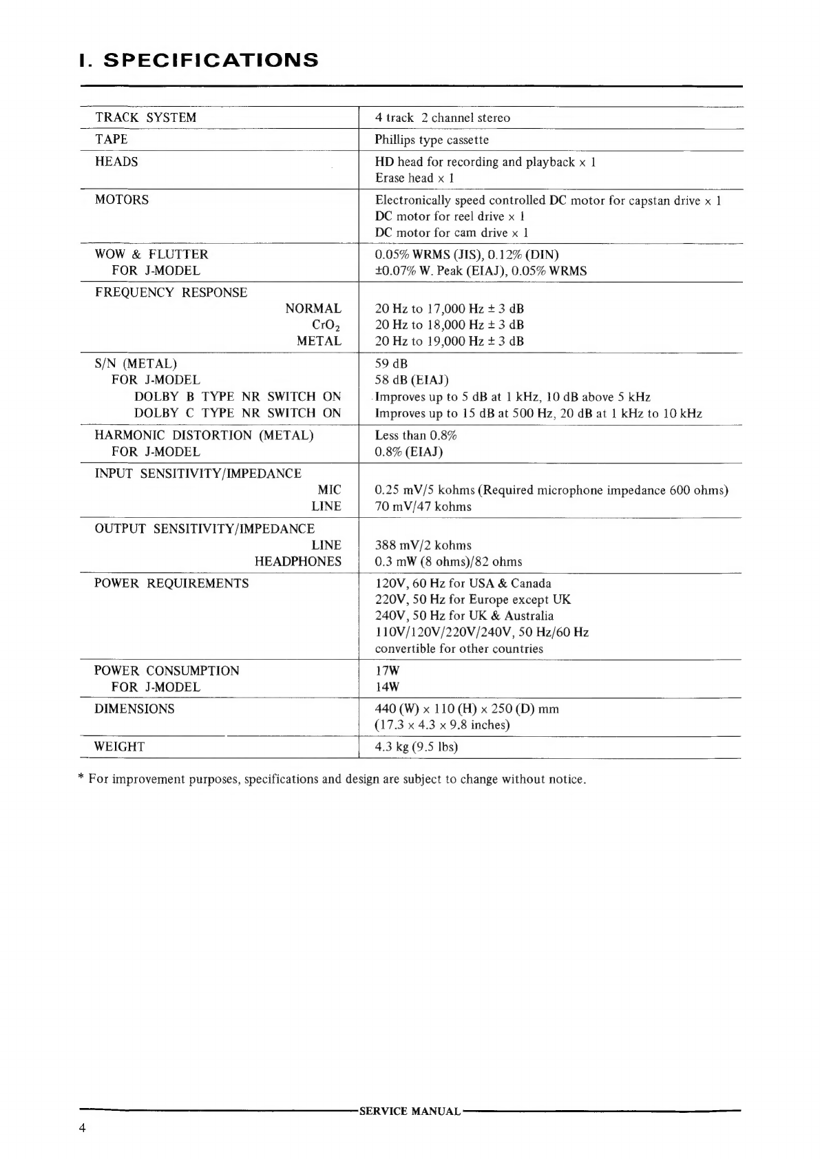
SPECIFICATIONS.
5.00002.
65
gee
Stew
bw
HR
ee
ee
eee
4
DISMANTLING
OF
UNIT
................
0.
eee
eee
ees
5
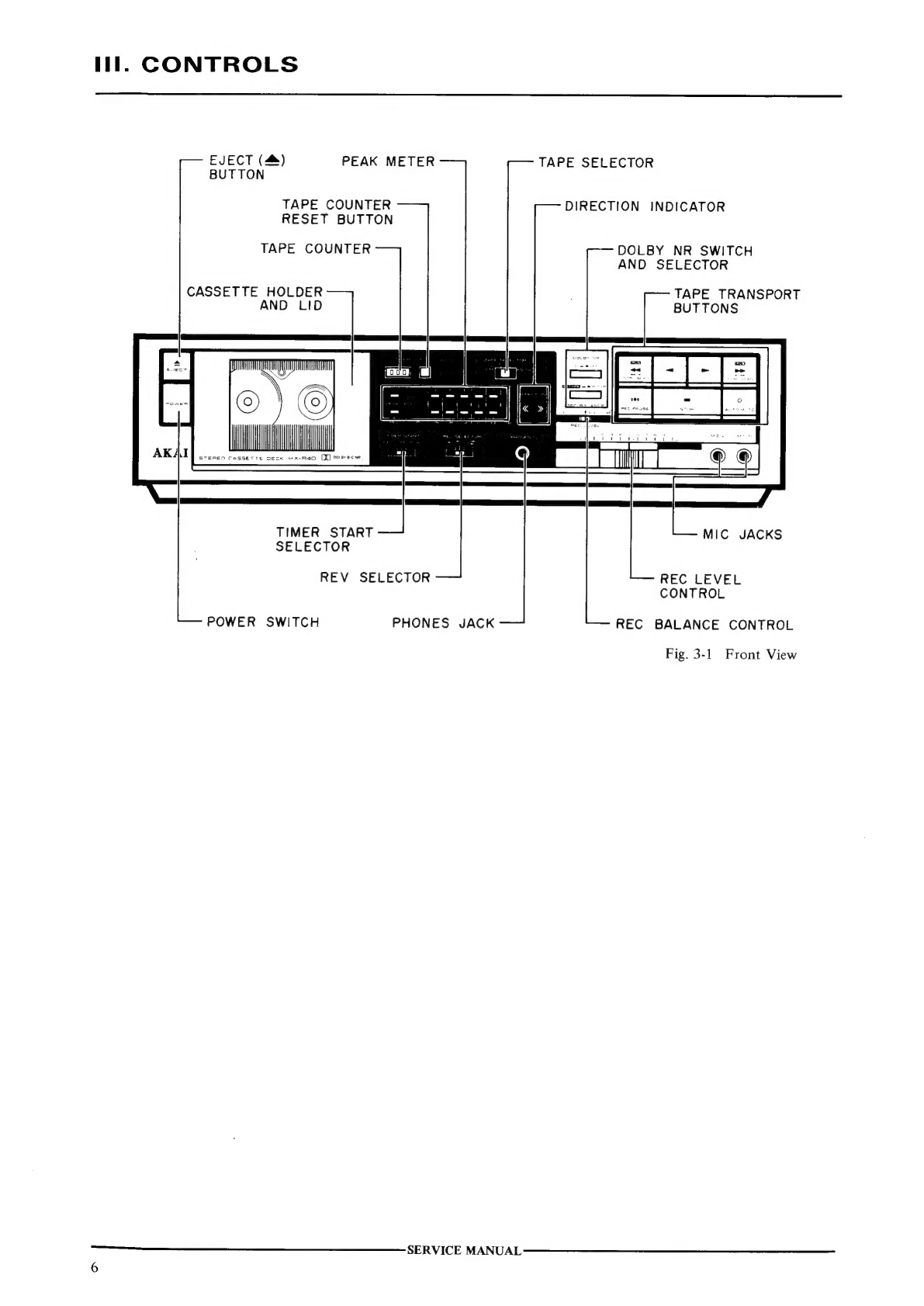
CONTROLS
|
2
esi
scc
cose
e
cok
we
ted
Bhs
Bin
eines
EERE
a
EARS
6
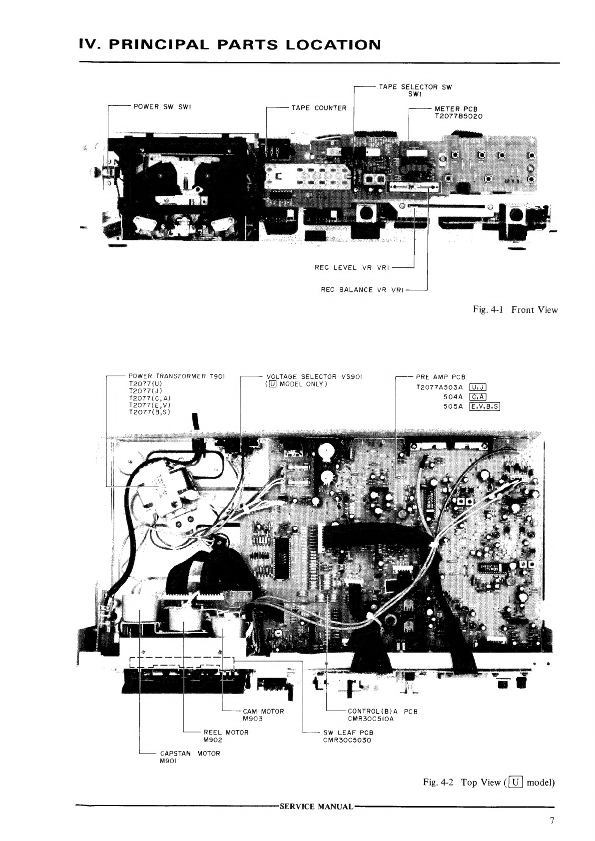
PRINCIPAL
PARTS
LOCATION
...........
0.0.0.
ee
eee
eee
ene
7
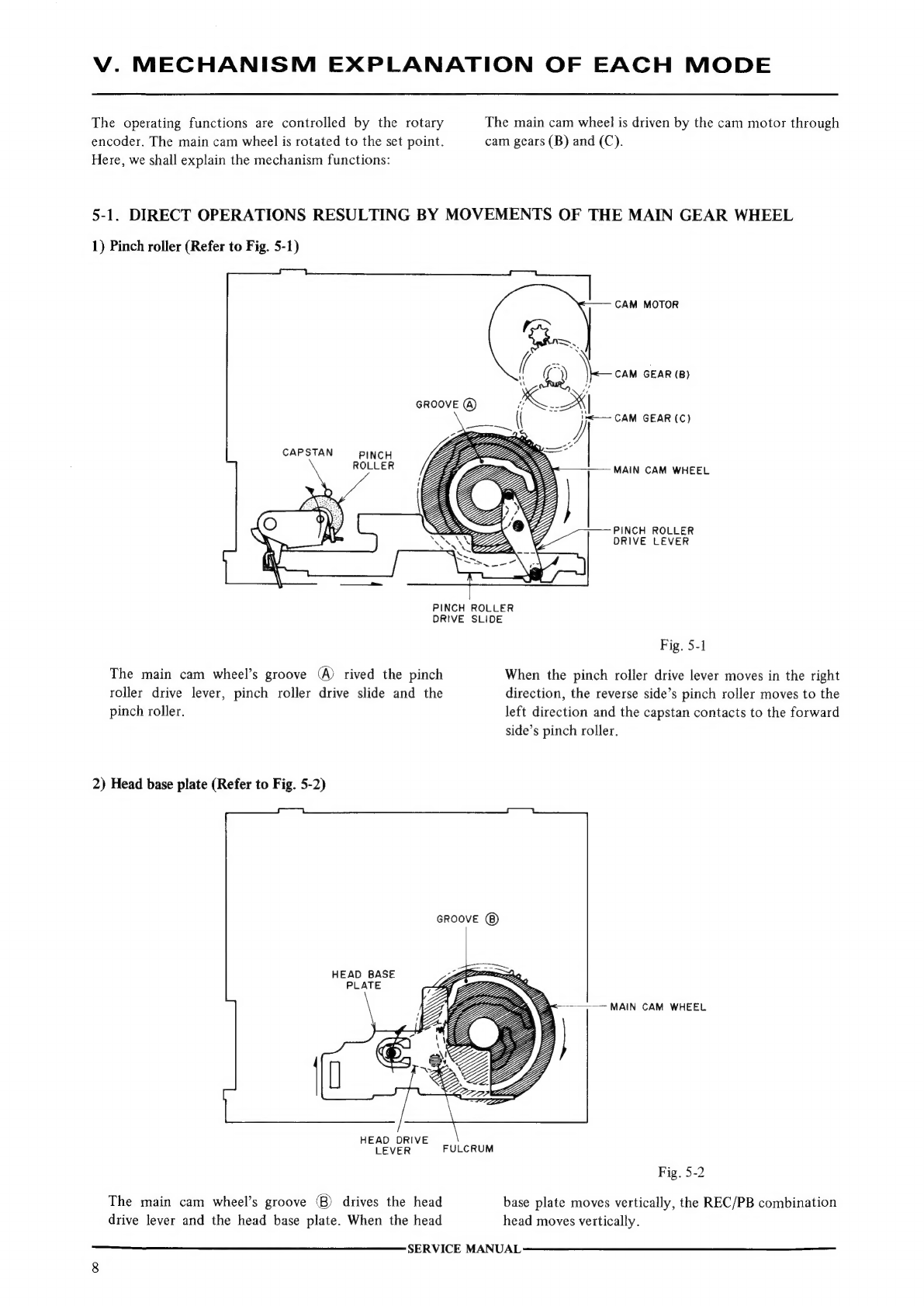
MECHANISM
EXPLANATION
OF
EACH
MODE..................
8
5-1.
DIRECT
OPERATIONS
RESULTING
BY
MOVEMENTS
OF
THE
MAIN
GEAR
WHEEL
.....
8
FIXING
PROCEDURES
FOR
CAM
WHEEL
AND
ROTARY
ENCODE
PCB.....
11
MECHANICAL
ADJUSTMENT
..........
0.000000.
02:
eae
eee
12
7-1.
PINCH
ROLLER
PRESSURE
MEASUREMENT
...............
12
7-2.
WINDING
TORQUE
MEASUREMENT
IN
EACH
MODE
........
12
7-3.
TAPE
SPEED
ADJUSTMENT
..........
2.0.0.0...
0000s
eee
12
HEAD
ADJUSTMENT
..
2.2.2.0...
.
cece
cece
eee
ees
13
8-1.
TAPE
GUIDE
HEIGHT
ADJUSTMENT.....................
13
8-2.
HEAD
HEIGHT
ADJUSTMENT
......................0...
13
8-3.
REC/PB
HEAD
AZIMUTH
ALIGNMENT
ADJUSTMENT
........
13
ELECTRICAL
ADJUSTMENT
..........0..
0.000.000
ee
eee
eee
ee
14
9-1.
QUICK
REVERSE
SENSITIVITY
ADJUSTMENT..............
14
9-2.
PRE-AMP
ADJUSTMENT...............
0.0.0...
.0
000000.
1S
PC
BOARD
TITLES
AND
IDENTIFICATION
NUMBERS............
16
For
basic
adjustments,
measuring
methods,
and
operating
principles,
refer
to
GENERAL
TECHNICAL
MANUAL.
SERVICE
MANUAL