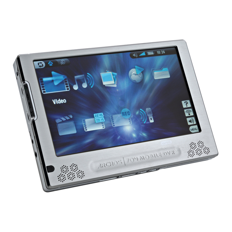
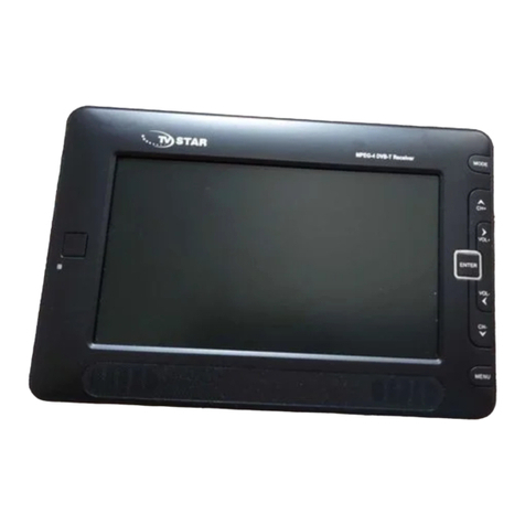
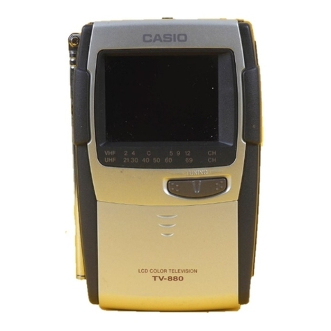
Teleton SPW 3000 User manual

Solid
State
12-inch
Portable
TV
MODEL
SWP
3000
SERVICE
MANUAL
TELETON
CONTENTS
Page
Page
|.
Specifications
wiaslalglb
leis
ara
tis
deo
eRe
anal
g
CuO
SUS
eRe
pe
eue
Dae
Hae
e
vi
}
b.
Adjustments
sinigieisse
srslvie-
GAG
a
despa
wea
Mares
elon
held
odie
piles
aera
g
eee
5
Pa
Controls
wUibiee(a
Wea
saulewes's
setae
Cuetied
bac
ens
be
ovebuse
ena
bebacrs
eae
nee
1
re
Alignment
Procedure
ORS
RTOS
RE
RE
Ce
ee
er
eee
ere
b
<>
Block
Diagram
Si
ahitieie
Greer
acaywig\e
ie
/a'o
ha
lee
fe
einvaki@
n/eeie
iw
sie
eihile
Sin
a.8S
wees
aioe
ene
sie
?
8.
Wiring
Diagrams
S'a'a
Tala
eiee'a.ge
capa
isin
(aralosg
SG
10
ale
sia
s'Shoe
lalb
ais
eine
sale
saie
oa
8
4.
Disassembly
Instructions
“sitesesteteteseerteteeeseaneneeeeen
2
9.
Replcaement
Parts
List
certs
sssreeteeseeseees
10.11
ioe
Parts
Location
Giaieca:
Sit:
wine
aiacn
drow
seas
e
wna
E
6
0c
Oalinete
de
een
eree
Ss
kee
se
4
10.
Schematic
Diagrams
1a
gh
1
few
(a
ca-aveis
(aha
‘O
a
Oia
hee
ews
le
oie
wa
ies,
Syn
foe
ewe
ie
1.
SPECIFICATIONS
Power
supply
:
220-volt
AC,
50/60
Hz.
Speaker
:
7
X18¢cm
or
12-volt
DC
from
battery
Picture
tube
:
12-inch,
9O°
deflection,
tinted,
Power
requirement
:
AC
30
watts
implosion
protection.
3]
ODWB4
DC
\3watts
Semiconductors
:
Channels
:
VHF
channels
2-12
Transistors
29
UHF
channels
21-69
Diodes
22
Inout
impedance
:
300
ohms
[Ext.}
Thermistors
4
Intermediate
frequencies
:
Varistor
Picture.
38.9
MHz
Cabinet
dimensions
:
46.4
wide
*
27.7
high
*
19cm
deep
Sound
33.4
MHz
Net
weight
:
1OKg
Audio
output
|
watt
2.
CONTROLS
—
ROD
ANTENNA
—
=
VERTICAL
HOLDIV-HOLD!
7
--—
—
BRIGHTNESSIBRIGHT
|
os
CONTRAST
——
ON.OFF/VOLUME
ION
OFF
VOL)
———
VHF
CHANNEL
SELECTOR
——
VHF
FINE
TUNING/UHF
CHANNEL
SELECTORIALL
CHANNEL!)
~~
FARPHONE
OUTLET
(EARPHONE
|
ROD-EXT
ANTENNA
SELECT
SWITCHIROD-EXT)
VHF
ANTENNA
TERMINALS
(VHF
|
UHF
ANTENNA
TERMINALS
+HUHF)
ROD
ANTENNA
LEAD
AUTOMATIC
GAIN
CONTROL
(AGC
SUB
VERTICAL
UNEARITY
iSUB
V-LIN)
HEIGHT
HORIZONTAL
HOLD(H-HOLD
|
POWER
ADAPTOR—~-
~—
VERTICAL
LINEARITY
(V-LEN}
MG
2.

3.BLOCK
DIAGRAM
Included
in
Power
PCB
Assembly
Sound
IF
Amp.
i
Sound:
Det.
|
Audio
Amp.
‘mp.
Audio
Output
2SC544
bel*15
188
2SC536
2
[28C544
las
2scsae
bf
25072
fy
15188
:
yee
|
258405
__
VHF
Tuner
ee
Lae
———
a
at
|
RF
Amp.
Mixer
Video
IF
Amp.
Video
Det.
Video
Amp.
|
Video
Output
CRT
*
SE5020
SE5021
|
25C4A74
20074
25C705
es
285C544
2aC6oy
310DWB4
?
bi
28C536
28C536
i]
ee
Amp
AGC
Keyer
Noise
Canceller
Sync.
Sep|
VIF.
SIF.
AGC
PCB
Assembly
:
|
mbly
|
Deflection
PCB
Asse
|
Vides-Ano.
Horiz.
Osc.
Local
Osc.
cas
=
[asa
UHF
UHF
Tuner
Phase
Inverter
IE
2SB187
|
1
|
25SB!
87
12V
:
{
Notes
x
Jimwiaheenen
Diodes
25830
||
Fo
pene
Printed
Circui
258407|
Power
PCB
Assembly
p
eteeeetee
VHF
&
UHF
ELECTRONIC
FILTER
4.
DISASSEMBLY
Removing
Chassis
(See
Fig.
2)
}
Pull
off
all
knobs
()
2)
Remove
cabinet
back.
I.
INSTRUCTIONS
Disconnect
power
adaptor.
2.
Remove
4
screws
(2)
from
cabinet
back
()
with
a
phillips
screwdriver.
3.
Pull
the
cabinet
back
gently
and
disconnect
antenna
plugs
(4).
A.
Remove
cabinet
back
(@).
3}
Disconnect
high
voltage
tip.
sound
output
lead
and
picture
tube
socket.
4)
Remove
chassis.
Ls
2
Si
4,
Removing
picture
Tube
(See
Fig.
2)
Remove
4
screws
(5)
from
chassis
with
a
phillips
screwdriver.
Remove
2
screws
(6)
from
control
plate
a
Phillips
screwdriver.
Slightly
loosen
a
screw(?).
Pull
out
chassis
together
with
deflection
yoke.
1}
Remove
chassis
{see
above).
2}
Remove
nut
(8)
holding
CRT
mounting
wire.
3)
Remove
screw(Q)
fixing
CRT
mounting
bracket.
4)
Litt
out
picture
tube.
Horiz.Drive
1
Horiz,
Output
Vert.
Output
81
SD-IAHF
t
Board
Assembly
Tuner
Note:
The
picture
tube
is
implosion-proof;
replace
with
an
identical
tube.
Removing
Printed
Circuit
Board
Assembly
1]
Remove
cabinet
back
(see
above}.
2)
Disconnect
multi-adaptor,
VIF
input
cable
and
video
amplifier
output
lead.
3}
Remove
printed
circuit
board
stopper
screw.
4)
Pull
out
printed
circuit
boord.
5)
To
remove
signal
P.C.B..
the
IF
input
plug
must
be
disconnected.

AYOLOANNOD
ILINW
IOldVAV
daMOd

5.
PARTS
LOCATION
CHASSIS
BACK
VIEW
ON-
OFF
/VOLUME
CONTRAST
/
BRIGHT
V-HOLD
7@
2)
CQ}
258376
|
TUNER
FLYBACK
TRANS
TR199.
2$B407
VERT
OUTPUT
is
H-HOLD
PC
BOARD
ASS’Y
PC
BOARD
ASS
Y
PC
BOARD
ASS
Y
(AUDIO,ELECTRONIC
FILTER
)
(VIE,
SIF,
AGC,
VIDEO
AMP.)
(DEFLECTION
|
TRANSISTOR
LOCATION
PC
BOARD
ASS'Y
TR106
(AUDIO.
ELECTRONIC
FILTER}
250544
(CE)
B-ADJ
TR116
TR120
2SC536
©
a
O
TR104
O
()
25D30
(B~F)
|
asco
a
im
G
ieee
(C~E)
TR112
rR?
je...
TR108
TR107
O
2SB536
(©
tR114
(C~E)
R113
2SD72
2SC536
(EP)
2SB187
2SA201
(E
°F)
O
||
O
©
O
pad.
2SC65Y
TR1O9
2SC860
O
2SB405
A
0
(C~E)
TR110
os
S278
pte
ees
ae
TR121.
»=TR122
258405
|
ao)
(A~D)O
5565
36
2SB187
2SB187
Le
C
|
atk
oie
fae
E)
V-FREQ
“
)
[|
ee
Bre
Pp
Ce
a
LEVEL
‘ts
9
BV
=
SUB-LIN
V-LIN
PC
BOARD
ASS'Y
PC
BOARD
ASS'Y
(DEFLECTION)
—{VIF,
SIF,
AGC,
VIDEO
AMP)
Figy
A

6.
ADJUSTMENTS
IMPORTANT
NOTICE
BEFORE
SERVICING
READ
CAREFULLY
THE
FOLLOWING
NOTES
BEFORE
ATTEMPTING
TO
TEST
OR
SERVICE
THIS
TRANSISTORIZED
RECEIVER.
AS
WITH
ANY
TRANSISTORIZED
DEVICE,
FULL
CARE
MUST
BE
TAKEN
NOT
TO
OVERLOAD
ANY
PART
OF
THE
CIRCUITRY.
].
Make
sure
that
the
DC
voltage
at
P9
is
1260.3
volts.
If
not,
adjust
the
Power
B-Adjust
Control
(R813)
to
obtain
this
DC
voitage
with
AC
supplied
to
the
set.
2.
When
servicing,
make
certain
the
AC
power
line
voltage
does
not
exceed
10%
more
than
rated
voltage.
3.
When
servicing
or
testing
the
set,
remove
the
1.5
Ampere
fuse
from
its
holder
and
connect
a
DC
ammeter
across
the
terminals
to
see
that
the
current
does
not
exceed
1.5
Ampere
during
AC
operation.
4.
When
adjusting
deflection
circuit,
including
the
horizontal
frequency
and
horizontal
stabilizer
control
adjustment
described
below,
AC
line
voltage
must
be
at
local
voltage.
5.
When
varying
horizontal
frequency,
do
not
deviate
more
than
+800
Hz
from
the
rated
center
frequency
of
15.625
MHz.
6.
Do
not
discharge.
arc
or
meter
the
2nd
anode
lead
of
the
picture
tube
in
an
attempt
to
protect
the
transistors.
Disconnect
the
lead
and
discharge
only
the
anode,
if
necessary.
Refer
to
the
following
paragraph
when
checking
high
voltage.
7.
While
the
receiver
is
in
operation,
do
not
attempt
to
disconnect
the
lead
wires
from
the
printed
circuit
board
assemblies.
8.
When
replacing
parts
in
the
receiver,
make
sure
the
power
supply
cord
is
disconnected.
9.
When
the
power
is
on,
do
not
attempt
to
short
any
portion
of
the
circuitry.
Such
shorting
may
damage
the
transistors
in
the
set.
FOCUS
ADJUSTMENT
Focus
adjustment
terminal
is
located
near
the
terminal
of
flyback
transformer
marked
1,
2
and
4.
Connect
the
white
lead
tram
the
picture
tube
socket
into
the
one
of
the
3
terminals
which
provides
the
best
focus.
DEFLECTION
YOKE.CENTERING
RING
ADJUSTMENT
1.
The
detlection
yoke
clamps
onto
the
neck
of
the
picture
tube.
Loosen
the
screw
on
this
clamp.
and
carefully
move
the
yoke
as
far
forward
as
possible
on
the
neck
of
the
picture
tube.
Rotate
the
yoke
until
the
top
and
bottom
edges
of
the
raster
squared
with
chassis.
Tighten
the
screw.
2.
Center
the
raster
horizontally
and
vertically,
and
eliminate
shaded
corners
by
simultaneously.
but
independently,
rotating
the
“entering
rings
until
the
best
effect
is
obtained.
HORIZONTAL
FREQUENCY
AND
HORIZONTAL
STABILIZER
CONTROL
ADJUSTMENT
}.
Tune
the
set
to
an
active
channel.
2.
Rotate
the
horizontal
hold
control
{R804
3K]
tully
counterclockwise.
Set
the
horizontal
frequency
control
(R810
10K)
to
the
center
of
its
range.
3.
Adjust
the
horizontal
stabilizer
coil
(L110)
10
obtain
12
bars
slanted
ito
the
right
on
the
screen.
4.
Adjust
the
horizontal
frequency
control
(R8}O
1OKito
obtain
|2
bars
slanted
to
the
left
with
the
horizontal
hold
contro!
in
its
fully
counter-
clockwise
position.
and
the
same
numbers
of
slanted
bars
lor]
or
2
less],
to
the
right,
with
the
horizontal
hold
control
in
its
fully
clockwise
position.
VHF
TUNER
ADJUSTMENT
If
the
range
of
the
VHF
fine
tuning
control
is
not
sufficient
for
tuning
in
a
clear
picture
on
one
or
more
channels.
the
oscillator
cores
require
adjustment.
1.
Set
the
VHF
fine
tuning
control
to
the
center
of
its
range.
2.
Adjust
the
oscillator
core
with
a
non-metallic
aligner
to
obtain
the
best
picture
condition,
beginning
with
highest
channel
and
working
down.
Do
not
press
the
oscillator
core
too
hard
durdng
this
adjustment.
HIGH
VOLTAGE
To
check
high
voltage,
measure
across
the
terminal
of
flyback
transformer
marked
2.
Correct
voltage
is
280
volts.

7.ALIGNMENT
PROCEDURE
PREPARATION
Alignment
is
an
exacting
procedure
and
should
be
undertaken
only
when
necessary.
The
following
equipment
is
required
in
alignment
work.
1.
A
Signal
generator
with
an
output
of
at
Jeast
0.]
volt.
having
a
frequency
range
that
covers
VHF,
UHF,
VIF
and
5.5MHz.
2.
An
RF
sweep
generator
with
a
frequency
range
covering
VHF
and
a
sweep
width
of
at
least
|
OMHz:
if
must
have
an
adjustable
outpul
of
at
least
0.1
volt.
3.
A
Vacuum
tube
volt
meter
[VTVM).
4.
A
Cathode
ray
oscilloscope,
preferably
with
a
wide
frequency
vertical
amplifier
and
voltage
calibrator.
.
An
isolation
transtormer.
It
is
best
to
connect
the
receiver
to
an
isolation
transformer
during
alignment.
Allow
atleast
15
minutes
for
the
set
to
warm
up
before
attempting
alignment.
VIDEO
IF
TRANSFORMER
&
TRAP
ADJUSTMENT
1.
Test
Equipment
Connections
:
Sweep
generator
ttre
Connect
to
S15
in
series
with
0.005
mfd
capacitor.
Signal
generator
**te*ster?
Connect
loosely
to
sweep
generator
output
lead,
to
provide
marker.
Oscilloscope]
terete
Connect
to
VIF
detector
output
at
TP-C.
in
series
with
a
]OK
ohm
resistor.
2.
Adjustment
:
2-1.
Turn
channel
selector
to
non-active
channel.
2-2.
Rotate
the
AGC
LEVEL
cantrol
(R811
j
fully
clockwise,
then
adjust
the
AGC
coniro!
(R812)
to
obtoin
0.4
—'0.45
volt
at
TP-B.
STEP
SIGNAL
GENERATOR
ADJUST
REMARKS
|
1
|
Adjust
33.4MHz
|
33.4MHz
L103
Adjust
for
minimum
output
of
33.4MHz
signal.
2}
Adjust
39.4MHz
|
39.4MHz
Adjust
for
minimum
output
of
39.4MHz
signal.
|
Trap
——os
—
—_—___—_
|
3
|
Adjust
Video
IF
|
35
MHz
VIF-1,
2,
3.and
4
Adjust
for
response
curve
shown
in
Fig.
7-A.
|
Transformer
SWEEP
ALIGNMENT
OF
VIDEO
IF
1.
Test
Equipment
Connections:
'
emer
Sweep
generator
trrtr
ts
Connect
to
VHF
antenna
input
terminal.
Signal
generator
sc****sss"**
Connect
loosely
to
sweep
generator
output
lead,
10
provide
marker.
Oscilloscope:
“steer
eterss
Connect
to
VIF
detector
output
at
TP-C.
in
series
with
a
1OK
ohm
resistor.
2.
Adjustment
:
2-|.
Turn
channe!
selector
to
a
non-active
channel
and
set
the
fine
tuning
knob
to
mid-position.
2-2.
Rotate
the
AGC
level
contro!
{R811}
fully
clockwise.
then
adjust
the
AGC
control
{R812)
to
obtain0.4
—
0.45
volt
at
TP-B.
2-3. Turn
channel
selector
to
channel
of
no
interference
and
set
fine
tuning
to
mid-position.
2-4.
Observe
the
over-all
response
curve
on
the
oscilloscope.
2-5.
Connect
signal
generator
and
adjust
VIF-1,2.3and
4,
and
the
tuner
mixer
collector
coil
[IFT}so
that
marker
positions
are
as
shown
in
Fig.
7-B.
During
this
alignment,
adjust
the
output
of
the
sweep
generator
so
that
the
waveform
an
the
oscilloscope
does
not
exceed
2
volts
p-p.
2-6.
Readjust
the
AGC
control
(R812)
to
obtain
0.4
—0.45
volt
at
TP-B.
then
tune
in
a
picture
and
readjust
the
AGC
level
contro!
(R811)
to
obtain
the
best
picture
quality.
SOUND
ALIGNMENT
1.
Test
Equipment
Connections
:
Signal
-Genetalvey
ster
sesetseeeent
annie
Connect
to
TP-C
and
TP-D
in
series
with
a
0.005
mtd
capacitor.
Vacuum
tube
volt
meter
cttttttttt
este:
Connect
to
TP-E
and
TP-F.
2.
Adjustment
:
STEP
SIGNAL
GENERATOR
ADJUST
REMARKS
1
|
Adjust
SIF-3
5.5MHz
SIF-3
Adjust
for
O
volt,
reading
across
TP-E
and
chassis.
5
|
Adjust
SIF-1,
2
6
SMHz
SIF-1.
2
ee
aes
reading
across
TP-F
and
chassis
3
|
Repeat
step
|
5.5MHz
Connect
signal
generator
‘6
Tee
4
|
Adjust
L106
5.5MHz
L106
Adjust
L106
for
minimum
beat
in
picture.

ANTENNA
TERMINALS
Signal
Generator
Fig.
5
Outline
Sound
33.4MHz
65+
10%
95+
5%
Generator
Diagram
of
VIF
Circuit
=
Le
ANTENNA
TERMINALS
40.4MHz
Piclure
38.9MHz
65+
10%
100%
2V
af
Oscilloscope
Piciure
40+
10%
0.005mid
95
5%
e
Generator
SIF
ViTVM
re
Signol
Fel
‘
O
OC
Fig.
6
Outline
Diagram
of
SIF
Circuit
=
Rie
75215%
100%
2v
Fig.
7
Response
Curve
for
Alignment
of
VIF
Fig.
8
Pictorial
of
VHF
Tuner
VHF
CHANNEL
TUNING

8.
WIRING
DIAGRAMS
8.
1
Signal
PCB
Assembly
a
|

sate
28
sua
ee
ee
sunt
sn
oe
Eee
ieee
Shy
cceauaen
fee
a
oe
mis
eis
oe
st
stSecwios
oS

9.
REPLACEMENT
PARTS
LIST
Stock
No.
Description
Note
Stock
No.
Description
Note
Cabinet
Assembly
Packing
Components
GT-Y4017
Escutcheon
Assemb}y
WLYV
T-Y6859
Inner
Cushion
Assembly
WL
GT-Y4558
Cabinet
Back
Assembly
WLV
T-360704
Inner
Cushion
WL-A
right
T-¥3096
Handle
Assembly
VG
T-360705
Inner
Cushion
WL-B
left
T-112966
Handie
Mounting
Bracket
VG-A
left
T-320567
Individual
polyethylene
Tube
KS
AC
cord
cover
T-1]12967
Handle
Mounting
Bracket
VG-B
right
T-344183
Inner
Cushion
WL
bottom
pad
T-113055
CRT
Mounting
Bracket
VL
T-344184
Tarpaulin
Cover
WL
cabinet
T-|
40283
Shield
Mounting
Spring
WL
safety
shield
GT-34558
Individual
Corrugated
Case
WLV
T-160287
CRT
Mounting
Wire
RG
T-344266
Outer
Corrugated
Case
WIZ
T-230150
Grounding
Chip
VL-B
T-344267
Tarpaulin
Cover
WIZ
outer
case
T-230154
Grounding
Chip
WL
T-350371
Inner
Cloth
Cover
WL
cabinet
T-250299
Handle
Shaft
VG
T-312636
Speaker
Grille
WL
Accessories
T-312678
Plug
Guide
Cover
WL
cabinet
back
GT-6570
Printed
Matters
Assembly
WLV
T-320674
Knob
Sheet TZ
VHF
knob
T-32031
1
Envelope
for
printed
Matters
HW-SR
T-320799
Protective
Film
WL
safety
shield
GT-34555
Owner
's
Manua!
WLYV
T-360396
CRT
Cushion
HQ
GT-34556
Schematic
Diagram
WLV
T-360509
CRT
Cushion
PE
T-J1622
Spare
Fuse
TCY
T-360522
Rubber
Band
ML
AC
cord
GT-34554
Parts
Location
Diagram
WILT
T-360706
Spacer
VG
handle
mounting
T-J3008
Loop
Antenna
ZSY
T-343645
Insulation
Label
TS
T-J4106A
Earphone
Ea
T-312638
Safety
Shield
WL
GT-34457
Guarantee
WLV
Chassis
Mechanical
Parts
Electrical
Components
T-¥1
660
Printed
Board
Stoper
Assembly
VG
T-A93
linearity
Coil
L114
T-111953
Capacitor
Holder
JIQ-GHA
T-D82
Deflection
Yoke
L109
J-1
12344
Trans
Mounting
Base
ML
power
trans.
T-F73A-315
Flyback
Transformer
71:05
TP
12390
Terminal
Mounting
Bracket
RG
antenna
terminal
T-J1037
Antenna
Terminal
WL
VHF
Tl
£2731
Trans
Mounting
Bracket
TC
power
trans.
T-L7062
Horizontal
Filter
Choke
2
T-112918
Chassis
VH
peaking
Coil
(330vH)
Lit
T-113057
Chassis
Frame
WL-A
right
T-P34EE
Power
Transformer
T106
T-113058
Chassis
Frame
WL-B
left
4-1151-64120
U-VTuner
T-113061
Chassis
Bracket
WL-A
T-V1009
Speaker
T-113062
Chassis
Bracket
WL-B
T-W28A
Vertical
Output
Coil
T102
T-1
13063
Chassis
Bracket
WL-C
T-U2201
8EF
Printed
Circuit
Board
Assembly
|
VIF,
SIF.
AGC)
T-113064
Plug
Mounting
Bracket
WL
T-U22019E
Printed
Circuit
Board
Assembly
(Deflection)
T-113065
VR
Mounting
Bracket
WL
T-U22025A
Printed
Circuit
Board
Assembly
(Audio.
Regulator)
T-113090
Capacitor
Holder
WL
T-L7095
Antenna
Matching
Trans.
T-111504-T
Trans
Hold
Band
HW-T
power
trans.
T-J1035
Antenna
Terminal
VG
GT-11404
Tuner
Mounting
Bracket
WLV
©-9131-04270
AC
Cord
T-16033
1
Wire
Holder
VG-A
T-L50
1]
UHF
Matching
Trans,
T-240259
Connecting
Tip
HW
T-261481
Radiator
Plate
TC
small
Socket,
Pulgs,
ete.
T-261
645
Chassis
Frame
WL-C
iop
T-E5214
3P
Terminal
Strip
{3PR]
OHB-U}
T-314983
Connect
Shaft
MI
H-hold
T-E5224
6P
Terminal
Strip
{6PR]
OH-U)
T-312192
printed
Board
Slide
Rail
QC
T-E0336
Earphone
Jack
T-312370
Insulation
Bush
A
T-E5023
Fuse
0.3A
T-320784
Wire
Band
VG-A
T-E5015
Fuse
1.5A
GT-34546
Insulation
Board
Fiber
WLV-A
T-E521]
1P
Terminal
Strip
{1
PRIOHA-U)
T-Y1668
FBT
Mounting
Bracket
Assembly
Wt
T-E3023
CRT
Socket
T-320785
Wire
Band
VG-B
T-E0462
Fuse
Holder
T-E5229
5P
Terminal
Strip
(5PR]
OQHA-U)
Control
Knobs
T-E4517
Rod
Antenna
GT-K046
VHF
Knob
Assembly
WLYV
T-E3047
AC
Adaptor
MP
GT-K027
Fine
Tuning
Knob
Assembly
SG
T-EOO77
4p
AC
Plug
T-K977
Small
Knob
Assembly
WL-A
ON-OFF/VOL
T-E3059
1OP
Multi
Connector
GT-K047
UHF
Indicator
Drum
Assembly
WLV
T-E3057
14P
Multi
Connector
T-31
2640
Small
Knob
WL-B
front
control
T-E3708
1P
Plug
T-E5207
AP
Terminal
Strip
14
PR]
OH-U)
T-E3035
Terminal
Socket
E
T-E6019
UL
Sleeve
C
T-E3029
Terminal
Socket
C
UHF
Feeder
T-E6009
Insulation
Sieeve
KT
UHF
Feeder

Stock
No.
Description
Variable
Resistors
]
8BFRH1
6L@
B-SOOK
]
8FRNI
6L@
B-3K
]
8FRNI6LQ
C-500
T8FRNIO6LQ
B-5K
24
FRQI
6LQ
A-10K
T-G1603
T-G1605
T-G1610
T-G1616
T-G1
604
Fixed
Capacitors
CC61K275t
Ceramic.
27pf
£%
CC62K150SL
150pf
+10%
CC6400M2000YY2K
0.002mid
+20%,
2K
60CMO|
0.01
mid
120%,
600V
60CJO68
0.068mid
+5%,
600V
5LK7
Lacquar,
7mfd
£10%,
50V
5MFI
Mylar
film.
O.lmfd
120%,
50V
T-C/6/2
Electrolytic.
5mid,
25V
T-C7084
470Omtd.
25V
ISOCTSO
50mid,
150V
300CT3
3mtd,
300V
T-C8142
2000mid.
20V
T-C8150SNZ
2200mid.
35V
Fixed
Resistors
1/2CK220
220
ohm
£10%,
1/2W
|
/2CK2.7K
2.7K
ohm
+10%,
1/2W
1
/2CK33K
33K
ohm
+10%,
1/2W
1
/2CK120K
120K
ohm
+10%,
1/2W
|
/2CK1
50K
150K
ohm
£10%,
1/2W
1
/2CM47
A7
ohm
20%,
1/2W
1
/2CM470
470
ohm
£20%,
1/2W
|
/2CMI1
0K
1OK
ohm
+20%,
|
/2W
|
/2CM33K
33K
ohm
+20%,
1/2W
|
/2CM1
00K
100K
ohm
+20%,
1/2W
|
/2CM1
50K
150K
ohm
20%
1/2W
|
/2CM330K
330K
ohm
20%,
1/2W
1
/2CM470K
A70K
ohm
420%,
1/2W
2XPK
330
Carbon
film.
330
ohm
2W
5W1LJ20
Wire
wound,
20
ohm
+5%,
5W
Semiconductors
and
Tube
T-Q5064
2SB407
{Red}
T-Q5064
2S5B407
T-Q5030
2SA375A
(Black)
T-E1045
DG-13
T-E}
029
SD-]
AHF
T-E1064
SD-
1
BHF
T-E1042
Selen
Rectifier
HW
T-E1024
Silicon
Rectifier
4-4
T-Q9082NS
31
ODWB4
Included
in
VHF
Tuner
SE5020
SE5021
SE300
1
Included
in
Video
Detector
{T-S1045}
T-E1031
1S$188
T-E10O14
]
N60
Included
in
PC
Board
Assembly
(VIF,
SIF.
AGC.
Video
T-Q5020
2SA201
(Blue)
T-Q5020
2S5A201
T-Q5063
ZoCoay
T-45053
25C536
{[A-D}
T-Q5053
25C536
{C-E}
T-Q5054
Z5C544
(CE
Note
Stock
No.
Description
Note
T-Q5055
2SC674
IC,
D,
E12
TRIOI
R803
T-Q5065
2SC
B60
ICE
TRIO2.
TRIO3
R804
T-E1031
1S188
DI.
D2,
DS,
DI7
R802
T-E1091
SV-31
D4
R805
T-E]1097
SD-}
AUF
D3
R801
Semiconductors
and
Tube
Included
in
PC
Board
Assembly
(dellection)}
VHF
Antenna
TQs027
25B]
87
TRI14
C625
T-Q5061
2SB405
(Red,
Orange.
Yellow.
Green}
-TRI18
C706,
C70
T-Q5053
2SC536
(BF
TRI16
C619
T-Q5053
2SC536
IE,FI
TRI17
C613
T-E1031
1S188
Dé,
D7.
D8,
D9
{Greenl
C615
T-E1036
SDT-06
TH-2,
TH-4
C320
T-E1038
SDT-20
TH-3
C126
T-£1043
TV
VDR-|
C614
C706
Included
in
PC
Board
Assembly
[Audio,
Regulator]
Cols
T-Q5027
2SB187
TRI21,
TRI22
C702
T-Q506|
25B405
(COMP)
(Red,
Orange,
Yellow)
TRIO9
C701
T-Q5062
2SD72
(COMP!
IRed,
Orange.
Yellow)
TRIOS
T-Q5053
2SC536
IE.FI
TRIOZ
T-Q5039
2SD30
TRI
20
BU
T-E1077
SDT-8
Di4
ney
T-£1026
SD-1
AH
Dié
Roe?
T-£1036
SDT-06
THI
RO34
Included
in
UHF
Tuner
poo!
AFI39
TRA
pe
SDB2A
Dol
ROz3
52617
TRS
ROSS
SE5050
TRE
R624
R711
R626
R627
R625
R709
R702
TR)
23
TRII5
TRII9
DIO
DI
DI2
DI5
D13
piclure
tube
TRI
TR2
TR3
Amp}
TRI}3
TRI12
TRIOS
TRIIO
TRI
1}
TRIO4.
TRIOS

11.
Schematic
Diagrams
11.
1
VHF
TUNER
RF
AMP
MIX
OSC
TO
VHF
ANT
TRI
SE5020
TR2
SE502
|
TR3
SE300
|
®
ANT
C16
C5
06
is
5~7P
1P
30P
ea
aa
1P
-
+100P
C4
aie
ie
C15
we,
C17
ae
ee
rage
|
10
rie
LT2
ae
R10
R13
C13
1500
R12
1500
C1
aan
1000P
3600
aoe
10000P
1000P
027
028”
SL”,
C21
10P
150P
40008.
C284
1000P
|
6800
an
RF
2200)
1502
4uH
C24
J
1000p
C19
R3
R4
ae
4000P
680
15K
C29
ee
es
eee
7
10P
C)
O)
©
C)
ae!
D
C25
50P
7
|
aco
TO
UHF
B
BR
FROM
UHF
IF
11.
2
UHF
TUNER
RF
AMP
MIX
OSC
TR4
AFI39
DO!
SD82A
TR5
S2617
TO
UHF
ANT
eT
IF
AMP
re
i
TR6
SE5050

PICTURE:
TUBE
a
ge
ee
er
=
eens
weer
1
'
AUDIO
AMP
VI
31
ODWB4
SIF
AMP
SOUND.
DET
1
TRIO7
2SC536(D.E)
!
!
TRIO6
2SC544
(C.D.E}
DI.D2
IS188x2
|
!
1
{
|
‘al
das
}
3
3
|
7,
|
I
Bape
!
’
9
SV
SIF
-2
SIF
-3
DI
R305
t
'
\
COLOR-CODE
VALUES
sy
T.$9005
Se
po008
5
ican
Aes
C308
!
!
.
O7
'
'e
c
!
=
@
\
10K
1
§Ou
12K
I
mot
a
e
|
R306
ae
ee
a
C302
|
a
a
e
es
sig
!
/
R320
;
a
if
2
.
102
F
goon
OTP
BU
220
'
R303
=
!'
(Bi
L-------
no
Wiis
FE
198
1P4
F3008R3123
tt
!
ey
Tea
HE.
sitheagityg
Ldes
Saookeai2g
Teas
|
be
Tel
|
a
reel
79308
iL
yp_teszoL
T:U220258___§
Ghv.ciss
olerance
“oO
2000P
t
el
ceo
ee
oe
ct
ay
a
tae
ap
a
ee
oes
Ree
aah
Percent
A
|
AP
OP
aS
PRE:
ON
ge
NIG
TM
UTE
PO
ed
NEE
CO
POP
ce
7
}
VIDEO
AMP
Lead
ill
120K
“YOK!
TRIO5
2SC65Y
!
mene
IST
VIF
AMP
2ND
VIF
AMP
3RD
VIF
AMP
tea’
TRIO4
250544
ioe
TRIO]
2SC674(C~E)2
TRIOZ2
2SC674(C~E)
TRIO3
2SC705(C~E)
ee
(C.D.E)
1-s9001
pan
a
C120
5000P
2700
?
C121
|
105
eee
pur
my
2200
oe
R1338
yir.g
"800
|
48V}
>]
62V
18039
7-S8040
100
[ts
8041
af
(on
a4
R
:
{~
|
OV
330,
Sooop/PONST
IMS
;
c20]
8
«a
.
=a
"F
$R203
Y
AN
=
S
|
[3
68
:
!
|
a
1
ie
a
j
}
R108
[22V]}
10K
C127126V
Baoan
sh20e
+t
dp
1500
R109
1Oz
SIF
|
2200
2700
'
|
390
RI
124
Rit3
1$188
R1223159007
ia
Se
i
e167
5000P
5600
ye
aaa
C301
1500
R205
[sooo
I.
|
5000P
i2
1
oy
'
|
ay
:
eee
re
ee
we
www
we
ee
i
ei
we
ee
=
S
3
CP
reef
wee
ewe
ow
oe
i
|
TR
Sscsae
rey)
ef
paneer
nnn
7
!
VERT
086
con
[
fie
YERT
OUrpUT
!
TRI
14
2SB187
|
Rao2
Soom
RI
Pe
ee
4
|
p
:
O
00
Rae
r50s{|
csoa!
+f
C505
c508|0!4,
viog
jav
30
u
za
T-D40q
i)
i]
To
Tu
AGC
'
iA
telt
Ge
5
SS
AgaR
OPN
oY
2
)
pas
1S
|
ema
3506
R125
ie
=
rok
(028)
+
R501
)
|
ane
Ri23g
c114_]+
i
|
10030
5603
Sy
7
ny
592
|
¢
S6
oe
C501
cs0z
$
VIE.SIE_AGCG
UN
i,
ye
ae
See
iS
RIL
Ta
a
{
{
oy
ELECTRONIC
FILTER
eR
ae
=
T
py
5
R620.
2700
—_—RBQ4_3K
3
|}
1K
r
a
HOR
HOLD
Be
peg
ea
,
TRI20
TRi2t
Ace
inGeoTee
Y
Qe
ee
en
AMEE
ee
Ge
HOR
DRIVE
--
-/
HOR
OUTPUT
co!
Bro—e
%
2SD30
TRI22
2SB187X2
roy
!
PHASE
INVERTER
.
Bg
TRII8
'
TF
R119
2SB375A
Oa
TRII7
2SC536
(E.F)
ey
eS
ae
ee,
CT; ner
ie
yy
aicenena
cote
|
P10
(11.2V}
}
TRI
16
2SC536
(B~F)
2SB405
!
LIt2
Black
i
O
—e
$2
!
O
1
DHOBEE
R709
Roms
4
8
HOR
FREQ
R616
56
oi
r
T.p34
33
10
(Tuner)
Gees
ae
a
z
ellow
!
se
f
!
680
‘Ol
07
ie
03
TeV"
T1104
;
oO
’
!
a
re
’
=
220H
|
|
cgo1
nV
}
t
H.V.RECT
=
(
a7
2
ITr
L+,-
iH
2
een
a)
pi2_"
pez,
R629
ws
ro”
1
(=1,9V)
f
rc
|
1
|
re
Rag
-02
POWER
:
C624
uee-@Fii
fs
Mois
|
UN
D1
300P
TH-4
pe
33
!
:
10
SD~
IAHF)
r-u220258
!
|
|
:
;
P3
'
'
2
C619
Tse
cae
3
Bisoroe
+
°%
wat
pie
RE
FEE
Og
|
ni
See
RE
<A
GPINTe
ot
O
A
T
R634
o|
EA
1)
The
voltag
included
in
the
diagram-are-evV=
ee
eee
eee
ee
ee
,
|
moh
cr
D
erdbe
vals
ESR
undercipral
(is
Condit
DEFL
UNIT
07.08
1S188x2
47
tT
C706
C707
R702
ines
on
when
the
indicated
AC
vol
tage
is
applied.
T-U220
|
9E
we
=P
3k
ox
.002
.002
1
4
20
2)
A
vacuum
tube
voltmeter
with
input
impedan
-
=
OO
TRI23
ce
of
10
megohm
He
since
measuring.
HF
a
is
|
rcul
tagram.
a
b
Oo
2SB407Red
Sse
GiGdLzi
En
haneae
way
be
made
witho-
ut
revision
of
the
diagram.
mee
7
eee

Printed
in
Japan
Oct.
‘68


