tell ecoLINE PRO User guide

ecoLINE PRO
INSTALLATION AND APPLICATION MANUAL
for device version v2.00
Document version 2.0 16.09.2020
Product models:
ecoLINE PRO 2G.IN4.R1
ecoLINE PRO 3G.IN4.R1
ecoLINE PRO 3GA.IN4.R1
ecoLINE PRO 4G.IN4.R1
ecoLINE PRO 4GA.IN4.R1

2
Table of contents
1ecoLINE PRO operation............................................................................................................ 4
1.1 Key functions of the product............................................................................................... 4
1.2Differences between the 2G, 3G, 3GA, 4G and 4GA models............................................. 4
1.3 Under Voltage Lock Out (UVLO) function .......................................................................... 4
1.4 Remote monitoring application overview............................................................................ 5
1.4.1 Event sending and acknowledging................................................................................ 5
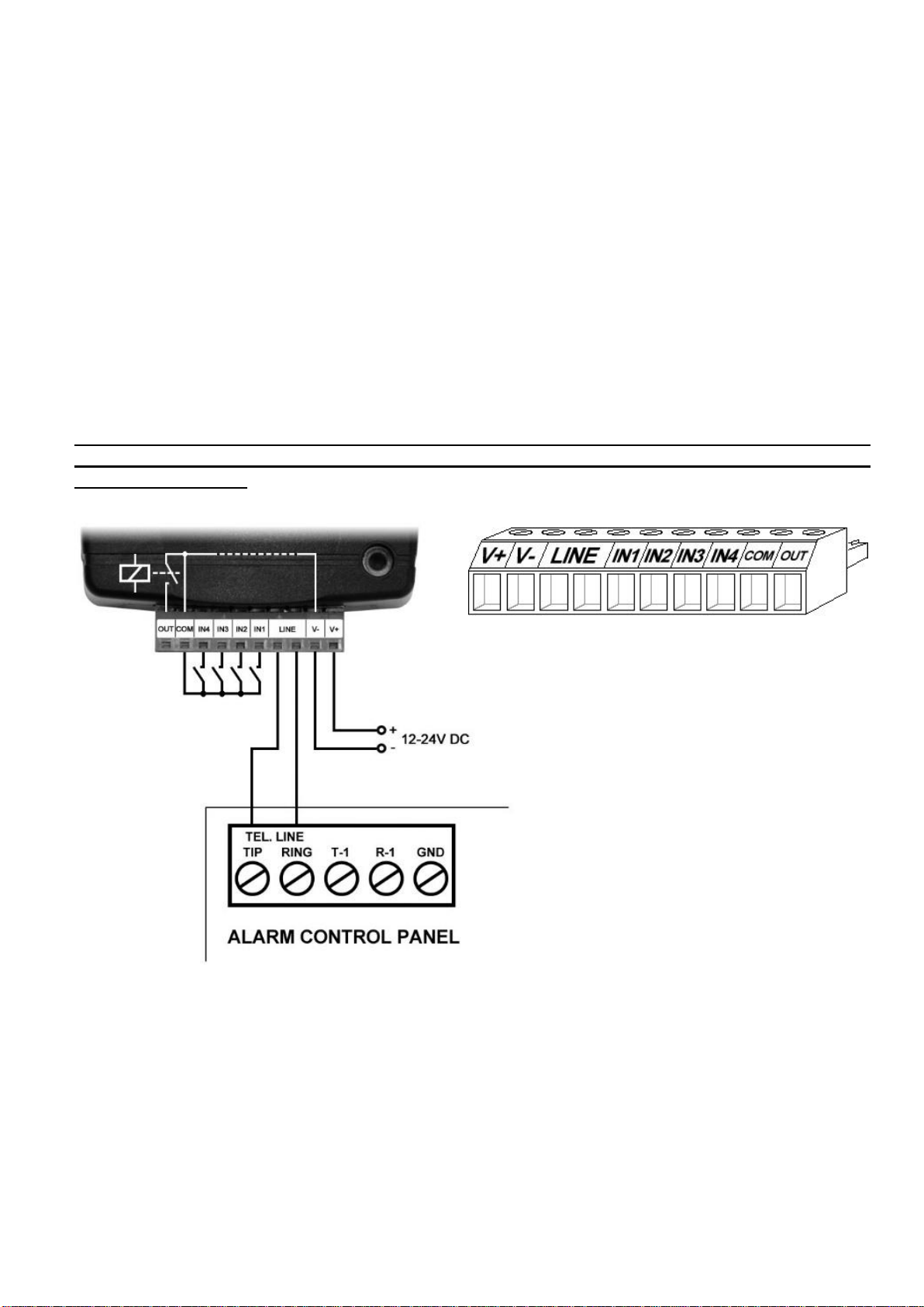
2Terminal wiring and putting into operation................................................................................. 6
2.1 Input wiring......................................................................................................................... 6
2.2 Connections and wiring...................................................................................................... 6
2.3 SIM card holder.................................................................................................................. 7
2.4 Connecting the antenna ..................................................................................................... 7
2.5 Installation.......................................................................................................................... 7
2.6 Putting into operation ......................................................................................................... 8
2.7 LED indicator signals.......................................................................................................... 8
2.8 Technical specification....................................................................................................... 8
3Configuring the ecoLINE PRO................................................................................................... 9
3.1 The user interface and configuration options of the software............................................. 9
3.2 Methods for connecting to the device................................................................................. 9
3.2.1 Configuring directly via USB ....................................................................................... 10
3.2.2 Remote connecting to devices via cloud service ........................................................ 11
3.2.3 Remote connecting to devices which are using the TEX-MVP protocol...................... 14
3.2.4 Remote connecting to devices which are using the TELLMon protocol...................... 15
4ecoLINE PRO programming software usage and feature descriptions ................................... 16
4.1 Connection menu............................................................................................................. 16
4.1.1 Viewing the settings options and configuring offline.................................................... 16
4.1.2 Connection type.......................................................................................................... 17
4.1.3 Device register............................................................................................................ 18
4.1.4 Server register ............................................................................................................ 20
4.2 Device settings menu....................................................................................................... 21
4.2.1 General....................................................................................................................... 22
4.2.2 Inputs.......................................................................................................................... 26
4.2.3 Output......................................................................................................................... 28
4.2.4 Mobile devices............................................................................................................ 30
4.2.5 Functions and permissions ......................................................................................... 32
4.3 Device status menu.......................................................................................................... 34
4.3.1 Status monitoring........................................................................................................ 34
4.3.2 Event monitoring......................................................................................................... 36
4.4 Software settings menu.................................................................................................... 38
4.4.1 Settings....................................................................................................................... 38
4.4.2 About .......................................................................................................................... 39

3
5Transparent serial port ............................................................................................................ 40
5.1 Remote programming of alarm control panels ................................................................. 40
5.1.1 Paradox alarm systems .............................................................................................. 41
5.1.2 DSC alarm systems.................................................................................................... 45
5.1.3 Premier and Premier Elite alarm systems................................................................... 48
5.1.4 Bentel alarm systems.................................................................................................. 51
5.1.5 Inim alarm systems..................................................................................................... 54
6Arming and disarming the alarm control panel through the mobile application........................ 58
7Updating the firmware ............................................................................................................. 59
7.1 Updating via USB............................................................................................................. 59
7.2 Updating remotely over the internet ................................................................................. 59
8Restoring the factory default settings ...................................................................................... 60
9Contents of the package.......................................................................................................... 60
10 About the manufacturer........................................................................................................... 60

4
1 ecoLINE PRO operation
1.1 Key functions of the product
The basic function of the ecoLINE PRO is forwarding reports of alarm control panels to remote
monitoring station over the mobile Internet, using multiple protocols, as well as sending Push
messages to users about these reports.
Features:
4 configurable NO/NC contact inputs for sending custom reports.
1 NO relay output controllable in the mobile application.
Forwards reports of the connected alarm system and events generated by own inputs to
remote monitoring station over the Internet, up to 2 IP addresses, using SIA IP DC-09,
TELLMon or TEX protocol.
ecoLINE PRO multiplatform mobile application (iOS, Android).
Sends Push messages about alarm system events and own input events to up to 20
registered mobile devices.
Configurable Contact ID event codes for each contact input, including partition and zone
options.
Output control through the mobile application, which can also be used to arm or disarm the
connected alarm system remotely.
1.2 Differences between the 2G, 3G, 3GA, 4G and 4GA models
The only difference between the 2G, 3G and 4G models is the type of the modem used.
The 3G (UMTS) and the 4G (LTE) communication makes possible higher speed, thereby
increasing the speed of reporting. The 2G, 3G and the 4G models can be used in Europe, while
the 3GA model is equipped with a pentaband UMTS/HSPA modem that can be used worldwide.
The 4GA model is equipped with a multiband LTE modem which can be used in North America.
There is no difference between the mentioned models with regard to the available functions or
configuration.
1.3 Under Voltage Lock Out (UVLO) function
The ecoLINE PRO is provided with built-in automatic power disconnection (Under
Voltage Lock Out) function. The device will turn off automatically when the supply
voltage drops below critical level, and turns back on when the voltage restores to the
operational level.

5
1.4 Remote monitoring application overview
The ecoLINE PRO communicates with SIA DC-09 receivers, TELLMon receivers and TEX-MVP
servers through the GSM service provider’s mobile switching center using the GPRS/UMTS/LTE
network, and then through the Internet. After processing and conversion, the receiver forwards
the received data packages through a serial port towards the monitoring PC that runs the alarm
monitoring software.
1.4.1 Event sending and acknowledging
The device attempts to sends the reports first to the configured primary IP address. If this fails,
it will attempt to send the reports to the backup IP address. The device will send the ACK signal
towards the alarm control panel only when it receives the ACK signal from at least one of the
configured receivers (IP addresses). If the device does not receive an ACK signal from any of the
configured receivers, it will attempt to resend the report up to 10 times per IP address.
An exception to this is when the device is banned in the given receiver, since in this case it will
not even attempt to send a report to that receiver. If the device still fails to send a report for the
10th attempt to a configured IP address, it will stop reporting the event and will no longer send
notification on the given event, but the event will be shown in the event logs.
If there are no remote monitoring receiver IP addresses configured at all, the device will send ACK
signals to the alarm control panel automatically.
Whether a remote monitoring receiver is configured or not, the device will send Push notifications
to the registered mobile devices on the event categories enabled in the settings and by users in
the mobile application.

6
2 Terminal wiring and putting into operation
2.1 Input wiring
For the inputs, the normally closed or normally open dry contact should be connected between
the given input (IN1…IN4) and the negative of the power input (V-) or the COM terminal.
If a normally open dry contact is used to activate the input, choose the NO (normally open) option
in the given input’s settings. In this case, the input will become activated when the open contact
between the given input (IN1…IN4) and the V- terminal (or the COM terminal) becomes closed.
If a normally closed dry contact is used to activate the input, choose the NC (normally closed)
option in the given input’s settings. In this case, the input will become activated when the closed
contact between the given input (IN1…IN4) and the V- terminal (or the COM terminal) becomes
open.
2.2 Connections and wiring
Attention! Do NOT connect the metallic parts of the GSM antenna connector or the
terminals of the device directly or indirectly to the protective ground, because this may
damage the device!
System terminal inputs and outputs:
V+ Supply voltage 12…24V DC (min. 500mA)
V- Supply voltage negative
LINE Simulated phone line output (connect to alarm system phone line input terminals)
IN1 Dry contact input 1
IN2 Dry contact input 2
IN3 Dry contact input 3
IN4 Dry contact input 4
COM Common negative for the contact inputs and the output (potential equivalent with V-)
OUT Relay output (switches the negative, max. 1A)

7
Attention!
Although the COM and V- terminals are equivalent, due to the design of internal circuit
protections, the COM terminal shall not be used as negative input for powering the device,
because this may damage the device! The COM terminal should only be used for
connecting the contact inputs and the relay output!
We would not advise powering the device directly from the power output of the alarm
control panel (AUX), as we can’t guarantee that the given output is able to fully operate the
device. Insufficient powering may lead to communication errors and frequent device
restarting, making it impossible for the device to operate normally as expected. To avoid
this, we suggest that you use a separate power supply for the device.
2.3 SIM card holder
The SIM card holder can be accessed by removing the cover of the aperture found on the device
enclosure. The cover can be removed by pressing it with your fingernail towards the LED at the
end where the gap is and then pulling it outwards. Insert the SIM card in the holder. The services
to be activated on the SIM card installed into the ecoLINE PRO device should be chosen
according to the services of the device. For communication with receivers and servers and use
with the mobile application, it requires a SIM card with available mobile Internet, that may use
either public or private APN.
Installing the SIM card:
1. Pull the metal security lock of the SIM holder towards the LED
until you hear a click.
2. Reach under the metallic security lock with your fingernail and
pull to open the holder.
3. Slide the SIM card into the opened part with the contacts facing
down, as shown in the figure.
Fold back the opened part together with the SIM card.
Secure the SIM card by pressing down carefully the metallic
security lock and pulling it towards the side of the enclosure until you
hear a click.
2.4 Connecting the antenna
Connect the GSM antenna to the FME-M socket. The device comes with an antenna which
provides good transmission under normal reception circumstances. In case of experiencing signal
strength problems or/and wave interference (fading), use another (directed) type of antenna or
find a more suitable mounting place for the antenna.
2.5 Installation
Please check the environment before installing:
Measure the GSM signal with your mobile phone. It may happen that the signal strength is
not satisfactory in the given place of mounting. In this case the planned place of installation
can be changed before mounting the device.
Do not mount the unit in places where it could be affected by strong electromagnetic
disturbances (e.g. near electric motors, high voltage, etc.).
Do not mount the unit in wet places or places with high degree of humidity.

8
2.6 Putting into operation
Disable voicemail and notification in SMS about missed calls on the SIM card installed
into the device.
The device can handle the SIM card’s PIN code. If you wish to use the
PIN code management, configure the SIM card’s PIN code in the programming
software in the “Device settings / General” section. Otherwise disable PIN code
request on the SIM card.
Check the SIM card to be installed correctly into the device.
Check the GSM antenna to be connected correctly to the device.
Check the wires to be connected as instructed in the wiring diagram.
You can power up the device (12-24V DC). Make sure that the power source is sufficient for
the operation of the ecoLINE PRO device. The nominal current consumption of the ecoLINE
PRO device is 120mA, however it may increase up to 500mA during communication and
output control. If the used power source is not sufficient for the operation of the device, this
may cause malfunctions.
2.7 LED indicator signals
Slowly flashing green
Normal operation,
connected to the mobile network.
Flashing red
The mobile service unavailable,
or system startup/restart is in progress.
Permanent red
SIM card error.
2.8 Technical specification
Supply voltage range: 12…24V DC
Nominal current consumption: 120mA
Highest current consumption: 500mA @ 12V DC, 250mA @ 24V DC
Operating temperature: -20ºC - +70ºC
Transmission frequency:
2G model: 850/900/1800/1900 MHz
3G model: 900/2100 MHz @UMTS, 900/1800 MHz @GSM
3GA model: 800/850/900/1900/2100 MHz @UMTS
850/900/1800/1900 MHz @GSM
4G model: 900/1800 MHz@GSM/EDGE, B1/B8@WCDMA,
B1/B3/B7/B8/B20/B28A@LTE
4GA model: B2/B4/B5@WCDMA, B2/B4/B5/B12/B13@LTE
Highest load supported on output: 1A @ 24VDC
Modem type:
2G model: Quectel M95
3G model: Quectel UG95
3GA model: Quectel UG96
4G model: Quectel EG91-E
4GA model: Quectel EG91-NA
Dimensions: 84 x 72 x 32mm
Net weight: 200g
Gross weight (packed): 300g

9
3 Configuring the ecoLINE PRO
The ecoLINE PRO can be configured the following ways:
By computer via USB, using the programming software.
By computer over the Internet, using the programming software.
The ecoLINE PRO programming software is compatible with the following operating systems:
Windows 10 (32/64 bit)
Earlier Windows operating systems are not supported by the software.
Installing the programming software: open the software setup application and follow the
instructions of the installation wizard to complete the installation. The latest version of the
programming software can be downloaded from the manufacturer’s website (http://www.tell.hu).
3.1 The user interface and configuration options of the software
The user interface language can be selected during installation.
The user interface appearance can be changed using the “Skin” dropdown-menu found in the
“Software settings” / “Settings” menu, where you can choose out of multiple appearance
themes.
The software saves changes related to appearance upon closing and applies the saved settings
when reopened.
Built-in help:
Some settings options in the software have an additional icon: or . By holding the mouse
pointer on the icon, a tooltip will be shown with information about the given option. Options with
the icon require expertise and special attention!
3.2 Methods for connecting to the device
For connecting to the device using the programming software, the following options are available:
USB: direct connection using a USB A-B cable.
TEX-MVP: remote connection through the Internet via the TEX-MVP server. This option can be
used by central monitoring stations that own a TEX-MVP server.
TELLMon: remote connection through the Internet via the TELLMon receiver. This option can be
used by central monitoring stations that own a TELLMon receiver.
Cloud: remote connection through the Internet via the cloud server operated by the manufacturer.

10
3.2.1 Configuring directly via USB
To start programming the device, follow the instructions below:
Open the ecoLINE PRO programming software.
Select the USB option in the “Connection type” menu, power up the device and connect it
to the computer using a USB A-B cable.
Enter the connection password.
oSuper administrator permission: full access to all settings. (Default password: 1234).
oInstaller permission: can only access settings enabled by the super administrator.
oConnecting without password: only restoring the factory default settings is available, if the
device has not been locked.
Click on the “Connect” button.
If the wrongpassword is entered, thesoftware connects to the device, but the samefunctions
will be available as when connecting without a password. To try a different password, close
the connection using the “Disconnect” button, enter the new password and then
connect again using the “Connect” button.
The software connects to the device using standard HID driver which is integrated in
Windows operating systems, thus there is no need to install special USB drivers. When the
device is connected to USB for the very first time, the Windows operating system installs the
drivers automatically.
The connection status is indicated by the USB status icon placed in the upper left corner of
the program window:
USB disconnected (green)
connected via USB (grey)
After connecting using the valid password, you can configure the device, change settings,
download event logs and monitor system status. The program will read the settings from the
device automatically after connecting to the device.
To close the connection, click on “Disconnect” button.

11
3.2.2 Remote connecting to devices via cloud service
This connection type can be used if the ecoLINE PRO device is connected to the cloud.
A prerequisite for this is that the APN should be configured, and a SIM card with available
mobile Internet service should be installed in the device, which may use either a public or
a private APN, but in the latter case, you have to arrange with the mobile service provider
to open the given private APN for accessing the cloud server IP address at 52.30.109.179,
port: 2020. In order to connect to the cloud, cloud usage should be enabled in the settings,
in the “Functions and permissions” menu. If you don’t want to enable permanent cloud
usage due to the data use that it involves, it is possible to command the device by SMS to
connect temporarily to the cloud, about which you can read more in the below.
With this connection type, connection between the device and the ecoLINE PRO programming
software will be established through the cloud server operated by the manufacturer.
Device password: the security password of the device (default superadmin password: 1234).
Device ID: the device identifier of the ecoLINE PRO device to which you wish to connect.
The format of this unique, burned-in during production and thereby unchangeable device identifier
used for cloud connection is: FF:FF:FF:FF:FF:FF (6x2 hexadecimal characters).
You can read the device ID of the given device in the “Device ID” section of the “Status
monitoring” menu, when connected to the device. The device will also send its device ID as a
reply to your request for connecting to the cloud server, sent by SMS to the device, about which
you can read more below.
Connecting to the device through the cloud server:
Select the “Cloud” option in the “Connection type” section.
If you have registered the device in the "Device register" menu, select the device you want
to access from the "Device Name" drop-down menu, or enter the device ID of the device
in the "Device ID" field, and the connection password in the “Device password” field.
Connection password:
oSuper administrator permission: full access to all settings. (Default password: 1234).
oInstaller permission: can only access settings enabled by the super administrator. The
installer password should be configured separately (see chapter “Connection type”).
oConnecting remotely without a password is not possible.

12
If cloud usage is enabled in the settings of the given device, the device keeps continuous
connection with the cloud based server. In this case, skip the SMS sending process
mentioned below. You can enable cloud usage in the “Functions and settings” menu.
If cloud usage is disabled, the device will not keep continuous connection with the cloud,
it will only connect upon request. Therefore, if this is the case, before trying to connect
remotely to the device, the request for connecting to the server should be sent by SMS to
the phone number of the SIM card installed in the device.
The device accepts the request for connecting to the cloud from any phone number, if the
valid device password is added in the message. The device password should be written in
the message at the beginning, as specified below. Commands sent with a missing device
password or a wrong password, will be ignored by the device and it will not send any reply
to these numbers.
The request command for connecting to the server is:
device password,connect#
device password: type the device password at the beginning of the message.
The superadmin and installer passwords are both accepted (default superadmin password:
1234).
Example on the usage of the command mentioned above: 1234,connect#
Send the mentioned request command for connecting to the server by SMS to the phone
number of the SIM card installed into the device and wait for the device’s reply. The device
will immediately send the reply below, and will start connecting to the cloud:
Connecting…
The device will send a new message as soon as it connects to the cloud successfully:
Connected to (IP address:port number)
ID=(device identifier)
If cloud usage is disabled in the device settings, the device remains connected to the cloud
for 10 minutes only, and thereafter, in case of inactivity it disconnects automatically.
Therefore, you have 10 minutes to connect to the device after it sends the reply message.
If no reply is received from the device within 1 or 2 minutes, please make sure that the
settings are correct and that the circumstances of sending the request for connecting satisfy
the conditions mentioned above. If you receive nomessage about a successful connection,
it means that the device failed to connect to the cloud.
Possible error messages:
Wrong password
Wrong superadmin or installer password
Missing APN
the APN is not configured

13
If the APN settings are not configured in the device, or if they are wrong, you can configure
these using the following SMS commands:
SMS command
Specification
device password,apn=APN#
Configuring the APN
device password,apn=APN,username,password#
Configuring the APN along with the
username and password belonging
to it
Example on the usage of the commands mentioned above:
1234,apn=internet#
1234,apn=net,guest,guest#
Possible error messages:
Wrong password
Wrong superadmin or installer password
Denied (no permission)
No permission to change the APN with the installer
password
Changing the APN settings failed
Changing the APN settings failed (typing error in the
message, or other error)
Wait for the device’s reply. After it has confirmed that it has connected to the cloud, continue
with the next step.
Click on the “Connect” button and wait for the connection to establish. The process
of connecting may take a few seconds.
The connection status is indicated by the status icon in the top left corner of the program
window:
disconnected (green)
connected (gray)
After connecting using the valid password, you can configure the device, change settings,
download event logs and monitor system status. The program will read the settings from
the device automatically after connecting to the device.
To disconnect from the device click on the “Disconnect” button.

14
3.2.3 Remote connecting to devices which are using the TEX-MVP protocol
This connection type can be used if the ecoLINE PRO device you wish to connect remotely
to, is connected to a TEX-MVP server. Also use this connection type if the ecoLINE PRO
device is connected to a TELLMon receiver and the device is configured to communicate
with the TELLMon receiver using the TEX-MVP protocol.
With this connection type, connection between the device and the ecoLINE PRO programming
software can be established through the server/receiver where the device is online.
Device password: the security password of the device (default superadmin password: 1234).
Server: the name of the server or receiver where the device is online. The server availabilities
should be recorded in advance in the “Server register” menu.
Device ID: the “TEX” identifier of the ecoLINE PRO to which you wish to connect to. The format
of the “TEX” device identifier is: FFF (3 hexadecimal characters).
Connecting to the device through a server/receiver which uses the TEX protocol:
Select the “TEX-MVP” option in the “Connection type” section.
If you have registered the device in the "Device register" menu, select the device you want
to access from the "Device Name" drop-down menu, or select the server/receiver where
the device is online, from the “Server” drop-down menu, and enter the device identifier in
the “Device ID” field, and the connection password in the “Device password” field. The
server availabilities should be recorded in advance in the “Server register” menu.
Connection password:
oSuper administrator permission: full access to all settings. (Default password: 1234).
oInstaller permission: can only access settings enabled by the super administrator. The
installer password should be configured separately (see chapter “Connection type”).
oConnecting remotely without a password is not possible.
Click the “Connect” button.
The connection status is indicated by the status icon in the top left corner of the program
window:
disconnected (green)
connected (grey)
After connecting using the valid password, you can configure the device, change settings,
download event logs and monitor system status. The program will read the settings from
the device automatically after connecting to the device.
To disconnect from the device click on the “Disconnect” button.

15
3.2.4 Remote connecting to devices which are using the TELLMon protocol
This connection type can be used if the ecoLINE PRO device you wish to connect remotely
to, is connected to a TELLMon receiver and the device is configured to communicate with
the TELLMon receiver using the TELLMon protocol.
With this connection type, connection between the device and the ecoLINE PRO programming
software can be established through the receiver where the device is online.
Device password: the security password of the device (default superadmin password: 1234).
Receiver: the name of the receiver where the device is online. The receiver availabilities should
be recorded in advance in the “Server register” menu.
Device ID: the device identifier of the ecoLINE PRO device to which you wish to connect to.
The format of this unique, burned-in during production and thereby unchangeable device identifier
used for the TELLMon protocol is: FF:FF:FF:FF:FF:FF (6x2 hexadecimal characters).
Connecting to the device through a receiver which uses the TELLMon protocol:
Select the “TELLMon” option in the “Connection type” section.
If you have registered the device in the "Device register" menu, select the device you want
to access from the "Device Name" drop-down menu, or select the receiver where the
device is online, from the “Server” drop-down menu, and enter the device identifier in the
“Device ID” field, and the connection password in the “Device password” field. The
receiver availabilities should be recorded in advance in the “Server register” menu.
Connection password:
oSuper administrator permission: full access to all settings. (Default password: 1234).
oInstaller permission: can only access settings enabled by the super administrator. The
installer password should be configured separately (see chapter “Connection type”).
oConnecting remotely without a password is not possible.
Click on the “Connect” button.
The ecoLINE PRO device that communicates using the TELLMon protocol is not
online continuously. The device connects to the receiver only when it sends
a supervision or event message, therefore after clicking the “Connect” button, you
have to wait until the device next connects to the receiver for sending a supervision
or event message. This is when the programming software will have possibility to
connect to the device. Therefore, if the device is configured to rarely send
supervision messages towards the TELLMon receiver, in this case the programming
software will be able to connect to the device after a long time only (depending on
the interval of supervision message sending).
The connection status is indicated by the status icon in the top left corner of the program
window:
disconnected (green)
connected (gray)

16
After connecting using the valid password, you can configure the device, change settings,
download event logs, monitor system status and perform controls. The program will read
the settings from the device automatically after connecting to the device.
To disconnect from the device click on the “Disconnect” button.
4 ecoLINE PRO programming software usage and feature descriptions
4.1 Connection menu
4.1.1 Viewing the settings options and configuring offline
Using the “Offline device selector” it is possible to view the settings options of the ecoLINE PRO
device and to configure and save the settings in advance offline, without connecting the device.
If you wish to view the settings options of the ecoLINE PRO device, or to configure and
save settings without connecting the device, click on the arrow found next to the
“Offline device selector” button, select the desired user level from the drop-down menu,
and then click on the “Offline device selector” button to load the settings options of the
selected permission level.

17
4.1.2 Connection type
In the “Connection type” menu the type of connection can be selected (USB or different options
for connecting over the Internet), information can be seen about the connection process, and the
installer and superadmin password can be changed. The default superadmin password is 1234.
If you wish to use the installer level access as well, for this the password should be configured
separately by clicking on the “Change Installer password” button (for “Actual password” enter
the superadmin password).
Available options:
Change Installer password:
The installer level
password can be changed
after clicking on this button.
Change Superadmin password:
The superadministrator level password can be changed after clicking on this button.
Enter the actual password, then the new password and its confirmation, then click “OK”.
The password should consist of at least 4, but not more than 8 characters.
Accepted characters are: numbers (0...9), lower case letters (a...z), and capital letters (A...Z).
Attention! The following characters should not be used: ^ ~ < > = | $ % " '.
Details: in this window you can follow the connection progress.
Restart the device:
If necessary, you can restart the connected device by clicking on this button.

18
Restore factory default settings:
By clicking on this button, you can restore the factory default settings in the device.
Restoring the factory default settings will erase the actual settings, therefore please
save your settings if needed. The reset process may take more than 1 minute and involves
a device restart. Wait until the device restarts and the LED indicator starts working again.
The option of restoring the factory default settings is also available without entering the
device password. The factory default settings cannot be restored if the device has been
locked in the settings. If you have forgotten the device passwords and the device is locked,
only the manufacturer can restore the factory default settings in the service center.
4.1.3 Device register
The device register serves for storing and easy handling of device contact details used for remote
programming. You can add new device contact details to the database and also edit, delete and
clone entries for easy adding of devices with similar contact details.
When connecting remotely, you can easily select by name the device you wish to connect to,
using the “Device name” drop-down menu, from the devices added to the database. You can also
connect remotely to a device directly from the device register, by selecting the device, and then
clicking on the Quick connect button.
If you add a new device availability in the connection type section, the program will add it
automatically to the device register database by using the device ID as device name, which you
can then change by editing the given entry. The database is stored locally on the computer.
If needed, you can import a database exported from an earlier version of the program using the
MMTool software available on the product’s page on the manufacturer’s website.

19
Function buttons available in the “Device register” menu:
: update the records from database
: quick remote connect to the selected device
: add new device
: clone entry (duplicate)
: edit entry
: delete entry
Data stored by the device register:
Device name: custom device name
Server/Receiver: you can configure multiple remote availabilities for the same device
(Cloud, TELLMon, TEX-MVP), according to what type of server or receiver the device connects
to. The availabilities of the servers or receivers should be recorded in advance in the “Server
register” menu, and then, in this drop-down menu you can choose from the servers and receivers
recorded there. If a device is available on multiple servers or receivers, and you want to record
the availabilities of the given device for all these, you can do this by adding separate records and
selecting the appropriate server or receiver for each record.
To make the device registration easier, for the Cloud and the TELLMon server type the program
will automatically read the device identifier from the device connected via USB, and will insert this
in the appropriate field.
Device ID: the device identifier. The format of the device identifier is:
- for cloud usage and the TELLMon protocol: FF:FF:FF:FF:FF:FF (6x2 hexadecimal
characters, unique, burned-in during production and thereby unchangeable device
identifier). The device ID (used for cloud connection and the TELLMon protocol) of the
connected device is shown in the “Status monitoring” menu / “Device ID” field.
- for the TEX-MVP protocol: FFF (3 hexadecimal characters).
Device password/Confirm device password: the superadmin or installer password configured
in the given device, depending on which one you want to use for connecting to the device.
SIM identifier (ICCID): the identifier of the SIM card inserted into the device (if the SIM card is
inserted, the software reads the ID automatically from the device and inserts the data in this field
when you create a new device availability entry). If automated reading fails, you can enter the ID
manually or copy it from the “Status monitoring” menu. The ICCID has no specific function, it’s
purpose is informational.
Device phone number: in this field you can enter the phone number of the SIM card installed in
the device. It has no specific function, it’s purpose is informational.
Comment: in this field you can enter custom comments related to the given device

20
4.1.4 Server register
The server register is used for storing the contact details of the monitoring servers and receivers
and to facilitate quick remote connecting to the devices. In the “Server register” menu you can
record your monitoring servers and receivers, and then you can associate these with the devices
in the “Device register” menu, when recording the contact details of your devices. You can add
new server or receiver contact details to the database and also edit, delete and clone entries for
easy adding of servers or receivers with similar contact details.
Function buttons available in the “Server register” menu:
: update the records from database
: add new server or receiver
: clone entry (duplicate)
: edit entry
: delete entry
Data stored by the server register:
Server/receiver name: custom server/receiver name.
Server/receiver address: the IP address or domain name of the server/receiver.
Port: the communication port number of the server/receiver.
Protocol: the communication protocol used by the server/receiver.
Server password: for the TEX protocol the 20 hexadecimal-character server password (5x4
characters separated by hyphen) is required.
Comment: in this field you can enter custom comments related to the given server/receiver.
Other manuals for ecoLINE PRO
1
This manual suits for next models
5
Table of contents
Other tell Cell Phone manuals