tell Adapter2 User guide

Adapter2
Adapter2 PRO
INSTALLATION AND APPLICATION MANUAL
for device version v5.00 and newer
Document version 5.0 04.09.2018
Product models:
Adapter2 2G.IN4.R1
Adapter2 3G.IN4.R1
Adapter2 3GA.IN4.R1
Adapter2 4G.IN4.R1
Adapter2 4GA.IN4.R1
Adapter2 PRO 2G.IN4.R1
Adapter2 PRO 3G.IN4.R1
Adapter2 PRO 3GA.IN4.R1
Adapter2 PRO 4G.IN4.R1
Adapter2 PRO 4GA.IN4.R1

2
Table of contents
1Adapter2 operation.................................................................................................................... 4
1.1 Key functions of the Adapter2 ............................................................................................ 4
1.2 Under Voltage Lock Out (UVLO) function .......................................................................... 4
1.3 System overview................................................................................................................ 5
1.4 Event sending and acknowledging..................................................................................... 5
1.5 Differences between the Adapter2 and the Adapter2 PRO models.................................... 5
1.6 Differences between the 2G, 3G, 3GA, 4G and 4GA models............................................. 5
2Terminal wiring and putting into operation................................................................................. 6
2.1 Input wiring......................................................................................................................... 6
2.2 Connections and wiring...................................................................................................... 6
2.3 SIM card socket.................................................................................................................. 7
2.4 Connecting the antenna ..................................................................................................... 7
2.5 Installation.......................................................................................................................... 7
2.6 Putting into operation ......................................................................................................... 8
2.7LED indicator...................................................................................................................... 8
2.8 Technical specification....................................................................................................... 8
3Configuring the Adapter2........................................................................................................... 9
3.1The user interface and configuration options of the software:............................................ 9
3.2 Methods of connecting to the device.................................................................................. 9
3.2.1 Configuring directly via USB ....................................................................................... 10
3.2.2 Remote connecting to devices via cloud service ........................................................ 11
3.2.3 Remote connecting to devices via peer-to-peer connection ....................................... 14
3.2.4 Remote connecting to devices which are using the TEX-MVP protocol...................... 15
3.2.5 Remote connecting to devices which are using the TELLMon protocol...................... 16
4How to use the Adapter2 programming software .................................................................... 17
4.1 Connection menu............................................................................................................. 17
4.1.1 Viewing the settings options and configuring offline.................................................... 17
4.1.2 Connection type.......................................................................................................... 18
4.1.3 Device register............................................................................................................ 19
4.2 Device settings menu....................................................................................................... 21
4.2.1 General....................................................................................................................... 21
4.2.2 Mobile devices (Adapter2 PRO only).......................................................................... 26
4.2.3 Reporting channels..................................................................................................... 28
4.2.4 Notification templates.................................................................................................. 31
4.2.5 Alarm system events................................................................................................... 33
4.2.6 Inputs.......................................................................................................................... 38
4.2.7 Input events ................................................................................................................ 39
4.2.8 Service events ............................................................................................................ 43
4.2.9 IP cameras (Adapter2 PRO only)................................................................................ 47

3
4.2.10 Voice messages.......................................................................................................... 49
4.2.11 Advanced settings....................................................................................................... 51
4.3 Device status menu.......................................................................................................... 53
4.3.1 Status monitoring........................................................................................................ 53
4.3.2 Event monitoring......................................................................................................... 55
4.3.3 System event logs....................................................................................................... 57
4.3.4 System logs ................................................................................................................ 58
4.4 Software settings menu.................................................................................................... 60
4.4.1 Settings....................................................................................................................... 60
4.4.2 About .......................................................................................................................... 61
5Managing voice messages via phone call............................................................................... 62
6Transparent serial port ............................................................................................................ 63
6.1 Remote programming of alarm control panels ................................................................. 63
6.1.1 Paradox alarm systems .............................................................................................. 64
6.1.2 DSC alarm systems.................................................................................................... 68
6.1.3 Premier and Premier Elite alarm systems................................................................... 71
6.1.4 Bentel alarm systems.................................................................................................. 74
6.1.5 Inim alarm systems..................................................................................................... 77
7Contents of the package.......................................................................................................... 81
8About the manufacturer........................................................................................................... 81

4
1 Adapter2 operation
1.1 Key functions of the Adapter2
The basic function of the Adapter2 is forwarding alarm control panel’s reports to remote
monitoring station using GPRS/UMTS connection.
Main functions:
Sends SMS, e-mail* and Push notification* with configurable message for each event
Reports events by SMS, e-mail* and Push notification*, by voice call with recordable
message, over IP to remote monitoring stations using different communication protocols and
by voice call using DTMF-based Contact ID protocol.
Reporting options:
SMS with configurable message up to 4 phone numbers
E-mail with configurable message up to 4 addresses*
Push notification with configurable message up to 4 users (mobile applications)*
Voice call up to 4 phone numbers with up to 15 uploadable or recordable messages
of 10 seconds each
Reporting to CMS (Central monitoring station) over IP up to 4 IP addresses using SIA
IP DC-09, TELLMon and TEX protocol
Reporting to CMS by voice call using DTMF-based (DC-05) Contact ID protocol
Up to 10 notification templates can be created and assigned to events in order to configure
the priorities of reporting channels used for reporting to CMS
Configurable Contact ID event codes for each input and service event, including partition
and zone options
Output control can be customized separately for each event using different operation modes
Available custom events: input events, service and error events (new and restore as well)
IP camera support: forwards the links of up to 4 IP cameras by e-mail and Push notification
along with the alarm messages
* available in the PRO model only
1.2 Under Voltage Lock Out (UVLO) function
The Adapter2 is provided with built-in automatic power disconnection (Under Voltage
Lock Out) function. If the supply voltage drops below 8.3V, the device turns off
automatically and it turns back on when the supply voltage is at least 11.6V.
The minimum supply voltage level required to turn the device on is 11.6V! After turned on
with supply voltage higher than 11.6V, the device can operate stably even at lower supply
voltage, but not lower than 8.3V.
If the device is powered from a power supply provided with a backup battery and there is no other
electrical load on the battery when charging fails (e.g. in case of a power cut), while the battery
discharges, the device turns off automatically at 8.3V voltage level.
Thereafter, if the battery is in good condition, it can regenerate and can reach the terminal voltage
of 11.6V where the device turns back on, then the battery may discharge again below 8.3V. This
may result a continuous switching on and off cycle that lasts until the battery can no longer
regenerate to the 11.6V voltage level. If this phenomenon occurs, the battery is flat and it should
be replaced.

5
1.3 System overview
The Adapter2 communicates with TELLMon receivers and TEX-MVP servers through the GSM
service provider’s APN gateway using the GPRS/UMTS network, and then through the Internet.
After processing and conversion, the server forwards the received data packages through serial
port towards the monitoring PC that runs the alarm monitoring software.
1.4 Event sending and acknowledging
The device sends the events simultaneously to the configured IP addresses. It sends the ACK
signal towards the alarm control panel only when it receives the ACK from at least one of the
configured receivers (IP addresses). Apart from this, event sending continues towards the other
receivers. If the device does not receive an ACK signal from any of the configured receivers, it
tries to report the event for at most 10 minutes. If reporting to the configured IP addresses fails for
the mentioned 10 minutes, the device stops reporting the event and will no longer send notification
on the given event, but the event will be shown in the event log.
1.5 Differences between the Adapter2 and the Adapter2 PRO models
There are differences in function between the Adapter2 and the Adapter2 PRO product models.
The Adapter2 PRO includes the following extra functions:
E-mail notification
Push notification
TELL Control Center multiplatform mobile application (iOS and Android)
IP camera support
1.6 Differences between the 2G, 3G, 3GA, 4G and 4GA models
The only difference between the 2G, 3G and 4G models is the type of the modem used.
The 3G (UMTS) and the 4G (LTE) communication makes possible higher speed, thereby
increasing the speed of reporting. The 2G, 3G and the 4G models can be used in Europe, while
the 3GA model is equipped with a pentaband UMTS/HSPA modem that can be used worldwide.
The 4GA model is equipped with a multiband LTE modem which can be used in North America.
There is no difference between the mentioned models with regard to the available functions or
configuration. For the 2G model, calls made through the GSM network will delay all other
communication, since 2G modems are unable to use multiple communication channels
simultaneously.

6
2 Terminal wiring and putting into operation
2.1 Input wiring
For the inputs, the normally closed or normally open dry contact should be connected between
the given input (IN1…IN4) and the negative of the power input (V-) or the COM terminal.
If a normally open dry contact is used to activate the input, choose the NO (normally open) option
at the given input’s settings. In this case the input becomes activated when the given input
(IN1…IN4) and the V- terminal (or the COM terminal) is shorted.
If a normally closed dry contact is used to activate the input, choose the NC (normally closed)
option at the given input’s settings. In this case the input becomes activated when shorting
between the given input (IN1…IN4) and the V- terminal (or the COM terminal) is removed.
2.2 Connections and wiring
Attention! Do NOT connect the metallic parts of the GSM antenna connector or the
terminals of the device directly or indirectly to the protective ground, because this may
damage the device!
System terminal inputs and outputs:
V+ Supply voltage 12…24V DC (min. 500mA)
V- Supply voltage negative
LINE Simulated phone line output (connect to alarm system phone line input terminals)
IN1 Dry contact input 1
IN2 Dry contact input 2
IN3 Dry contact input 3
IN4 Dry contact input 4
COM Common negative for the contact inputs and the output (potential equivalent with V-)
OUT Relay output (switches the negative, max. 1A)

7
Attention! Although the COM and V- terminals are equivalent, due to the design of internal
circuit protections, the COM terminal shall not be used as negative input for powering the
device, because this may damage the device! The COM terminal should only be used for
connecting the contact inputs and the relay output!
2.3 SIM card socket
The SIM card socket can be accessed by removing the cover of the aperture found on the device
enclosure. The cover can be removed by pressing it with your fingernail towards the LED at the
end where the gap is and then pulling it outwards. Insert the SIM card in the socket. The services
to be activated on the SIM card installed into the Adapter2 device should be chosen according to
which services of the device you wish to use. Basically, for communication with receivers and
servers it requires a SIM card with mobile Internet access that may use either public or private
APN. The functions that use SMS sending need SMS service and the ones that use calls require
GSM voice call service.
Installing the SIM card:
1. pull the metal security lock of the SIM socket towards the LED
until it clicks
2. reach under the metallic security lock with your fingernail and
pull it outwards to open the socket
3. slide the SIM card into the opened part with the contacts facing
down, as shown in the figure
Close back the opened part together with the SIM card.
Press down carefully the metallic security lock and pull it towards
the side of the enclosure until it clicks.
2.4 Connecting the antenna
Connect the GSM antenna to the FME-M socket. The device comes with an antenna which
provides good transmission under normal reception circumstances. In case of
experiencing signal strength problems or/and wave interference (fading), use another
(directed) type of antenna or find a more suitable mounting place for the antenna.
2.5 Installation
Please check the environment before installing:
Verify the GSM signal strength with your mobile phone. It may happen that the signal
strength is not satisfactory in the given place of mounting. In this case the planned
place of installation can be changed before mounting the device.
Do not mount the unit in places where it could be affected by strong electromagnetic
disturbances (e.g. near electric motors, high voltage, etc.).
Do not mount the unit in wet places or places with high degree of humidity.

8
2.6 Putting into operation
Disable voicemail and notification in SMS about missed calls on the SIM card installed
into the device.
The device can handle the SIM card’s PIN code. If you wish to use the
PIN code management, configure the SIM card’s PIN code in the programming
software at the “Device settings / General” section. Otherwise disable PIN code
request on the SIM card.
Enable caller identification service on the SIM card at the GSM service provider
(this service might not be enabled by default, please check). To enable this service, install
the SIM card into a mobile phone and call the customer service of the card’s GSM service
provider and enable the service in the menu, or visit one of the service provider’s personal
customer services and ask to enable this service on the SIM card.
Check the SIM card to be installed correctly into the device.
Check the GSM antenna to be connected correctly to the device.
Check the wires to be connected as instructed in the wiring diagram.
You can power up the device (12-24V DC). Make sure that the power source is sufficient
for the operation of the Adapter2 device. The nominal current consumption of the
Adapter2 device is 120mA, however it may increase up to 500mA during
communication and output control. If the used power source is not sufficient for the
operation of the device, this may cause malfunctions.
2.7 LED indicator
Slowly flashing green
Normal operation,
connected to GSM network
Flashing red
GSM service unavailable
or system startup/restart in progress
Permanent red
SIM card error
2.8 Technical specification
Supply voltage range: 12…24V DC
Nominal current consumption: 120mA
Highest current consumption: 500mA @ 12V DC, 250mA @ 24V DC
Operating temperature: -20ºC - +70ºC
Transmission frequency: 2G model: 850/900/1800/1900 MHz
3G model: 900/2100 MHz @UMTS, 900/1800 MHz @GSM
3GA model: 800/850/900/1900/2100 MHz @UMTS
850/900/1800/1900 MHz @GSM
4G model: 900/1800 MHz@GSM/EDGE, B1/B8@WCDMA,
B1/B3/B7/B8/B20/B28A@LTE
4GA model: B2/B4/B5@WCDMA, B2/B4/B5/B12/B13@LTE
Highest load supported on output: 1A @ 24VDC
Modem type: 2G model: Quectel M95
3G model: Quectel UG95
3GA model: Quectel UG96
4G model: Quectel EG91-E
4GA model: Quectel EG91-NA
Dimensions: 84 x 72 x 32mm
Weight: 200g (packed: 300g)

9
3 Configuring the Adapter2
The Adapter2 can be configured the following ways:
By computer via USB, using the programming software.
By computer over the Internet, using the programming software.
The Adapter2 programming software is compatible with the following operating systems:
Windows 10 (32/64 bit)
Windows 8.x (32/64 bit)
Windows 7 (32/64 bit)
Installing the programming software: open the software setup application and follow the
instructions of the installation wizard to complete the installation. The latest version of the
programming software can be downloaded from the manufacturer’s website (http://www.tell.hu).
The Adapter2 programming software can be used to configure all Adapter2 device models.
3.1 The user interface and configuration options of the software:
The user interface language can be selected
from the “Language”selection drop-down menu
found in the “Software settings” / “Settings”
menu.
The user interface skincan be changed using the
“Skin” dropdown-menu found in the “Software settings” / “Settings” menu, where you can
choose out of multiple appearance themes.
Context-sensitive help:
The “Help” section on the right side of the program window opens a context-sensitive help by
dragging the mouse pointer above it. You can pin the help window thus making it always visible,
by clicking on the “thumbtack” icon in the top right corner of the window. If you click on any of the
settings fields within the program window, you will get brief information about the given option or
setting in the help window. The content of the help window can be scrolled up and down using
scrollbar placed on theright side of the help window, or using the mouse wheel after clicking inside
the help window. For better readability, the help window can be resized by dragging the left-side
border of the window horizontally using the mouse.
The software saves the changes related to appearance upon closing and applies the saved
settings when reopened.
3.2 Methods of connecting to the device
For connecting to the device using the programming software, the following options are available:
USB: direct connection using a USB A-B cable.
TEX-MVP: remote connection through the Internet via the TEX-MVP server. This option can be
used by central monitoring stations that own a TEX-MVP server.

10
TELLMon: remote connection through the Internet via the TELLMon receiver. This option can be
used by central monitoring stations that own a TELLMon receiver.
Cloud: remote connection through the Internet via the cloud server operated by the manufacturer.
Peer-to-peer: direct remote connection via the Internet. This option can be used if the computer
running the programming software and the SIM card installed into the Adapter2 device are in the
same VPN or a private APN.
3.2.1 Configuring directly via USB
To start programming the device, follow the instructions below:
Open the Adapter2 programming software.
Select the USB option in the “Connection type” menu, power up the device and connect it
to the computer using a USB A-B cable.
Enter the connection password.
oSuper administrator permission: full access to all settings. (Default password: 1234).
oAdministrator permission: full access to all settings except device identification settings.
oConnecting without password: only restoring the factory default settings is available, if the
device has not been locked.
Click on the “Connect” button.
If the wrongpassword isentered, thesoftware connects to the device, butthe same functions
will be available as when connecting without a password. To try a different password, close
the connection using the “Disconnect” button, enter the new password and then
connect again using the “Connect” button.
The software connects to the device using standard HID driver which is integrated in
Windows operating systems, thus there is no need to install special USB drivers. When the
device is connected to USB for the very first time, the Windows operating system installs the
drivers automatically.
The connection status is indicated by the USB status icon placed in the upper left corner of
the program window:
USB disconnected (green)
connected via USB (grey)
After connecting using the valid password, you can configure the device, change settings,
download event logs and monitor system status.
To close the connection, click on “Disconnect” button.

11
3.2.2 Remote connecting to devices via cloud service
This connection type can be used if the Adapter2 device you wish to connect remotely to,
can use the cloud service. For this, the APN settings should be configured in the “General”
settings menu and it is also necessary to have installed into the device a SIM card with
available mobile Internet service which uses public APN, or, if using a private APN,
accessing the cloud server IP address should be enabled in the given APN.
If the “Cloud usage” option is enabled and the cloud server availabilities are configured in the
same menu, the device will be continuously online, so it can be accessed at anytime via the cloud
server. Otherwise it will only connect upon request sent by SMS, as mentioned below.
With this connection type, connection between the device and the Adapter2 programming
software will be established through the cloud server operated by the manufacturer.
The “System logs” option of the programming software cannot be used in case of remote
connection over the Internet.
Admin password: the security password of the device (default superadmin password: 1234).
Server address: the IP address of the cloud server (default: 54.75.242.103).
Port: communication port number of the cloud server (default: 2020)
Device ID: the device identifier of the Adapter2 device to which you wish to connect.
The format of this unique, burned-in during production and thereby unchangeable device identifier
used for cloud connection is: FF:FF:FF:FF:FF:FF (6x2 hexadecimal characters).
You can read the device ID of the given device in the “Device ID” section of the “Status
monitoring” menu, when connected to the device. The device will also send its device ID as a
reply to your request for connecting to the cloud server, sent by SMS to the device, about which
you can read more below.
Connecting to the device through the cloud server:
Enter the connection password.
oSuper administrator permission: full access to all settings. (Default password: 1234).
oAdministrator permission: full access to all settings except device identification settings.
oConnecting remotely without a password is not possible.
Select the “Cloud” option in the “Connection type” section.
Fill in the “Server address”, “Port” and “Device ID” fields.

12
If cloud usage is enabled in the settings of the given device, the device keeps continuous
connection with the cloud server. In this case skip the SMS sending process mentioned
below. Cloud usage can be enabled in the “General” settings menu. If cloud usage is
disabled, the device will not keep continuous connection with the cloud server, it will only
connect upon request. Therefore, if this is the case, before trying to connect remotely to
the device, the request for connecting to the server should be sent by SMS to the phone
number of the SIM card installed into the device. The device accepts the request for
connecting to the cloud server from any phone number if the valid device password is
specified in the message. For this, the device password should be added in the message
using the “PWD” parameter, as specified below. In case that the connecting request
command is sent without specifying the device password, or with the wrong password, the
device will ignore the request and will not send any reply to these numbers.
The request command for connecting to the server is: CONNECT,PWD=device password#
PWD: the device password can be specified using this parameter. The superadmin and admin
passwords are both accepted (default superadmin password: 1234).
Example on the usage of the command mentioned above: CONNECT,PWD=1234#
Send the mentioned request command for connecting to the server by SMS to the phone number
of the SIM card installed into the device and wait for the device’s reply. As soon as the device
connects to the server, it will send the following reply:
Connected to (IP address:port number)
ID=(device identifier)
If cloud usage is disabled in the device settings, the device remains connected to the cloud server
for 10 minutes only and thereafter in case of inactivity it disconnects automatically, therefore you
have 10 minutes to connect to the device after it sends the reply message.
If no reply is received from the device within 1 or 2 minutes, please check if the settings are correct
and if the circumstances of sending the request for connecting satisfy the conditions mentioned
above.
Possible error messages:
Missing APN
the APN is not configured
Network connection error
the device is unable to connect to the Internet due to an
error, faulty settings, or missing Internet service

13
If the APN or the cloud server settings are not configured in the device, or are faulty, you can
configure these using the following SMS commands:
SMS command
Specification
APN=APN,PWD=device password#
Configuring the APN
APN=APN,username,password,PWD=device password#
Configuring the APN along
with the username and
password belonging to it
CONNECT=server address:port nr,PWD=device password#
Configuring the cloud server
address and port number,
then connecting to the server
Example on the usage of the commands mentioned above:
APN=internet,PWD=1234#
APN=net,guest,guest,PWD=1234#
CONNECT=54.75.242.103:2020,PWD=1234#
Wait for the device’s reply. After it has confirmed that it has connected to the cloud server, continue
with the next step.
Click on the “Connect” button and wait for the connection to establish. The process
of connecting may take a few seconds.
The connection status is indicated by the status icon in the top left corner of the program
window:
disconnected (green)
connected (gray)
After connecting using the valid password, you can configure the device, change settings,
download event logs and monitor system status.
To disconnect from the device click on the “Disconnect” button.
14
3.2.3 Remote connecting to devices via peer-to-peer connection
This connection type can onlybe used in a private APN, or through a virtual private network
(VPN) connected to the given private APN. In case of private APN, for the SIM cards in the
given APN, sending and receiving data between each other should be enabled. The SIM
card installed into the Adapter2 device you wish to connect remotely to, should have a
static IP address and should be part of the given private APN, respectively VPN, just like
the computer from which you wish to connect to the device. If the computer is not part of
the given private APN through VPN, then you can connect to the device trough a mobile
Internet stick connected to the computer, in which you have to use a SIM card that is part
of the given private APN. Also, the APN settings should be configured in the device you
wish to connect to. These settings are available in the “General” settings menu.
With this connection type, connection between the device and the Adapter2 programming
software will be established directly (peer-to-peer).
The “System logs” option of the programming software cannot be used in case of remote
connection over the Internet.
Admin password: the security password of the device (default superadmin password: 1234).
Device IP address: the static IP address of the device you wish to connect to.
Connecting to the device through peer-to-peer connection:
Enter the connection password.
oSuper administrator permission: full access to all settings. (Default password: 1234).
oAdministrator permission: full access to all settings except device identification settings.
oConnecting remotely without a password is not possible.
Select the “Peer-to-peer” option in the “Connection type” section.
Enter the static IP address of the device you wish to connect to in the “Device IP address”
field.
Click on the “Connect” button.
The connection status is indicated by the status icon in the top left corner of the program
window:
disconnected (green)
connected (gray)
After connecting using the valid password, you can configure the device, change settings,
download event logs and monitor system status.
To disconnect from the device click on the “Disconnect” button.

15
3.2.4 Remote connecting to devices which are using the TEX-MVP protocol
This connection type can be used if the Adapter2 device you wish to connect remotely to,
is connected to a TEX-MVP server. Also use this connection type if the Adapter2 device is
connected to a TELLMon receiver and the device is configured to communicate with the
TELLMon receiver using the TEX-MVP protocol.
With this connection type, connection between the device and the Adapter2 programming
software can be established through the server/receiver on which the device is online.
The “System logs” option of the programming software cannot be used in case of a remote
connection over the Internet.
Admin password: the security password of the device (default superadmin password: 1234).
Server address: the IP address or domain name of the server on which the device is online.
Port: the communication port number (default TEX communication port: 3333)
Server password: the 20 hexadecimal-character password of the TEX server (5x4 characters
separated by hyphen).
Device ID: the “TEX” identifier of the Adapter2 to which you wish to connect to. The format of the
“TEX” device identifier is: FFF (3 hexadecimal characters).
Connecting to the device through a server/receiver which uses the TEX protocol:
Enter the connection password.
oSuper administrator permission: full access to all settings. (Default password: 1234).
oAdministrator permission: full access to all settings except device identification settings.
oConnecting remotely without a password is not possible.
Select the “TEX-MVP” option in the “Connection type” section.
Fill in the “Server address”, “Port”, “Server password” and “Device ID” fields.
Click the “Connect” button.
The connection status is indicated by the status icon in the top left corner of the program
window:
disconnected (green)
connected (grey)
After connecting using the valid password, you can configure the device, change settings,
download event logs and monitor system status.
To disconnect from the device click on the “Disconnect” button.

16
3.2.5 Remote connecting to devices which are using the TELLMon protocol
This connection type can be used if the Adapter2 device you wish to connect remotely to,
is connected to a TELLMon receiver and the device is configured to communicate with the
TELLMon receiver using the TELLMon protocol.
With this connection type, connection between the device and the Adapter2 programming
software can be established through the receiver on which the device is online.
The “System logs” option of the programming software cannot be used in case of remote
connection over the Internet.
Admin password: the security password of the device (default superadmin password: 1234).
Receiver address: the IP address or domain name of the receiver on which the device is online.
Port: communication port number (the default TELLMon communication port is: 3535)
Device ID: the device identifier of the Adapter2 device to which you wish to connect to.
The format of this unique, burned-in during production and thereby unchangeable device identifier
used for the TELLMon protocol is: FF:FF:FF:FF:FF:FF (6x2 hexadecimal characters).
Connecting to the device through a server/receiver which uses the TELLMon protocol:
Enter the connection password.
oSuper administrator permission: full access to all settings. (Default password: 1234).
oAdministrator permission: full access to all settings except device identification settings.
oConnecting remotely without a password is not possible.
Select the “TELLMon” option in the “Connection type” section.
Fill in the “Receiver address”, “Port” and “Device ID” fields.
Click on the “Connect” button.
The Adapter2 device that communicates using the TELLMon protocol is not online
continuously. The device connects to the receiver only when it sends a supervision
or event message, therefore after clicking the “Connect” button, you have to wait
until the device next connects to the receiver for sending a supervision or event
message. This is when the programming software will have possibility to connect to
the device. Therefore, if the device is configured to rarely send supervision
messages towards the TELLMon receiver, in this case the programming software
will be able to connect to the device after a long time only (depending on the interval
of supervision message sending).
The connection status is indicated by the status icon in the top left corner of the program
window:
disconnected (green)
connected (gray)
After connecting using the valid password, you can configure the device, change settings,
download event logs, monitor system status and perform controls.
To disconnect from the device click on the “Disconnect” button.

17
4 How to use the Adapter2 programming software
4.1 Connection menu
4.1.1 Viewing the settings options and configuring offline
The Adapter2 programming software supportsall Adapter2 device models, therefore the software
shows the settings options available specifically in a given device model, which are different from
the common parameters (e.g. differences between the PRO and non PRO device models) only
when connecting the given device model, i.e. an Adapter2 device has to be connected in order to
show the specific settings options of that device model.
However, using the “Offline device selector” it is possible to view the settings options of any
Adapter2 device model and to configure and save the settings in advance offline, without
connecting the device.
If you wish to view the settings options of a Adapter2 device model, or to configure and
save settings without connecting the device, click on the arrow found next to the
“Offline device selector” button, select the desired device model from the drop-down menu
and then click on the “Offline device selector” button to load the settings options of the
selected device model.

18
4.1.2 Connection type
In the “Connection type” menu the type of connection can be selected (USB or different options
for connecting over the Internet), information can be seen about the connection process, and the
admin and superadmin password can be changed. The default superadmin password is 1234.
If you wish to use the admin level access as well, for this the password should be configured
separately by clicking on the “Change Admin password” button (for “Actual password” enter
the superadmin password).
Available options:
Change Admin password:
The administrator level password can be changed after clicking on this button.
Change Superadmin password:
The superadministrator
level password can be
changed after clicking on this
button.
Enter the actual password, then the
new password and its confirmation,
then click “OK”. The password
should consist of at least 4, but not
more than 8 characters. Accepted characters are: numbers (0...9), lower case letters (a...z), and
capital letters (A...Z).
Attention! The following characters should not be used: ^ ~ < > = | $ % " '.
Details: in this window you can follow the connection progress.

19
Restart the device:
If necessary, you can restart the connected device by clicking on this button.
Restore factory default settings:
By clicking on this button, you can restore the factory default settings in the device.
Restoring the factory default settings will erase the actual settings, therefore please
save your settings if needed. The reset process may take more than 1 minute and involves
a device restart. Wait until the device restarts and the LED indicator starts working again.
The option of restoring the factory default settings is also available without entering the
device password. The factory default settings cannot be restored if the device has been
locked in the settings. If you have forgotten the device passwords and the device is locked,
only the manufacturer can restore the factory default settings in the service center.
4.1.3 Device register
The device register serves for storing and easy handling of device availabilities used for remote
programming. You can add new device availabilities to the database and also edit, delete and
clone entries for easy adding of devices with similar availabilities.
When connecting remotely, you can easily select by name the device you wish to connect to from
the “Device name” drop-down menu, out of the devices added to the database. In the drop-down
menu the program indicates which types of connection have been configured for the given device,
which helps you select the appropriate connection type.
If you add a new device availability in the connection type section, the program will add it
automatically to the device register database by using the device ID as device name, which you
can then change by editing the given entry. The database is stored locally on the computer.

20
Function buttons available in the “Device register” menu:
: save database to file
: load database from file
: add new device
: clone entry (duplicate)
: edit entry
: delete entry
Data stored by the device register:
Device name: custom name
SIM identifier (ICCID): the identifier of the SIM card inserted into the device (if the SIM card is
inserted, the software reads the ID automatically from the device and inserts the data in this field
when you create a new device availability entry)
Comment: in this field you can enter custom comments related to the given device
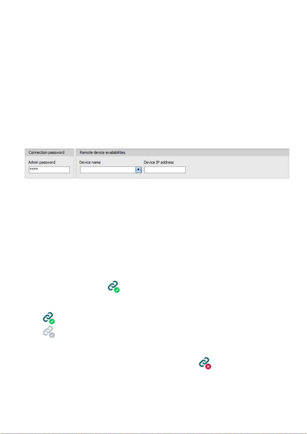
Connection type: you can configure multiple remote availabilities for the same device
(TEX-MVP, TELLMon, cloud, peer-to-peer), according to what type of server or receiver the device
connects to. The availabilities belonging to given types of connection can be configured under the
tabs labeled with the name of the connection type.
A green icon will be shown on the tabs of connection types for which device availabilities have
already been provided, and a red icon will be shown on the tabs where availabilities have not
been configured or the data are deficient. To make it easier for you, the program will automatically
fill in the data fields for connection types for which the availabilities are available (e.g. if the device
is connected via USB, the program knows the availability of the cloud server, and the necessary
device identifier will be read automatically from the device via USB).
Server/receiver address: the IP address or domain name of the server/receiver
Device IP address: the static IP address of the device (in case of private APN)
Port: the communication port number of the server/receiver
Server password: (for TEX-MVP protocol only) the 20 hexadecimal-character server password
(5x4 characters separated by hyphen)
Device ID: the device identifier. The format of the device identifier is:
- for cloud usage and the TELLMon protocol: FF:FF:FF:FF:FF:FF (6x2 hexadecimal
characters, unique, burned-in during production and thereby unchangeable device
identifier). The device ID (used for cloud connection and the TELLMon protocol) of the
connected device is shown in the “Status monitoring” menu / “Device ID” field.
- for the TEX-MVP protocol: FFF (3 hexadecimal characters)
Other manuals for Adapter2
3
This manual suits for next models
11
Table of contents
Other tell Cell Phone manuals


