tell Pager4 PRO Series User manual

Pager4
Pager4 PRO
INSTALLATION AND USER MANUAL
for device version v7.02
Document version: 7.03 03.09.2021
Product models:
Pager4 2G.IN4.R2
Pager4 2G.IN6.R1
Pager4 3G.IN4.R2
Pager4 3G.IN6.R1
Pager4 3GA.IN4.R2
Pager4 3GA.IN6.R1
Pager4 4G.IN4.R2
Pager4 4G.IN6.R1
Pager4 4GA.IN4.R2
Pager4 4GA.IN6.R1
Pager4 WiFi.IN4.R2
Pager4 WiFi.IN6.R1
Pager4 PRO 2G.IN4.R2
Pager4 PRO 2G.IN6.R1
Pager4 PRO 3G.IN4.R2
Pager4 PRO 3G.IN6.R1
Pager4 PRO 3GA.IN4.R2
Pager4 PRO 3GA.IN6.R1
Pager4 PRO 4G.IN4.R2
Pager4 PRO 4G.IN6.R1
Pager4 PRO 4GA.IN4.R2
Pager4 PRO 4GA.IN6.R1
Pager4 PRO WiFi.IN4.R2
Pager4 PRO WiFi.IN6.R1

2
Table of contents
1Main functions of the product .................................................................................................... 4
1.1 Differences between the Pager4 and the Pager4 PRO models ......................................... 4
1.2 Differences between the 2G, 3G, 3GA, 4G, 4GA and WiFi models.................................... 5
1.3 Differences between the IN4.R2 and the IN6.R1 models................................................... 5
2Connecting the terminals and putting into operation ................................................................. 5
2.1 Under Voltage Lock Out (UVLO) function .......................................................................... 5
2.2 Input wiring......................................................................................................................... 6
2.3 Output wiring...................................................................................................................... 6
2.4 Connections and wiring (IN4.R2 model)............................................................................. 6
2.5 Connections and wiring (IN6.R1 model)............................................................................. 7
2.6 SIM card holder.................................................................................................................. 8
2.7 Connecting the antenna..................................................................................................... 8
2.8 Status LED signals............................................................................................................. 8
2.9 Installation.......................................................................................................................... 9
3General information on the notification process ...................................................................... 10
4Configuring the Pager4 ........................................................................................................... 11
4.1 The user interface and configuration options of the software........................................... 11
4.2 Methods for connecting to the device............................................................................... 12
4.2.1 TELL servers and receivers........................................................................................ 12
4.2.2 Configuring directly via USB ....................................................................................... 13
4.2.3 Remote connecting to devices via cloud service ........................................................ 14
4.2.4 Remote connecting to devices via peer-to-peer connection ....................................... 17
4.2.5 Remote connecting to devices which are using the TEX protocol............................... 19
4.2.6 Remote connecting to devices which are using the TELLMon protocol...................... 20
5Pager4 programming software usage and feature descriptions .............................................. 22
5.1 Connection menu............................................................................................................. 22
5.1.1 Viewing the settings options and configuring offline.................................................... 22
5.1.2 Connection type.......................................................................................................... 23
5.1.3 Device register............................................................................................................ 25
5.1.4 Server register ............................................................................................................ 28
5.2 Device settings menu....................................................................................................... 31
5.2.1 General....................................................................................................................... 32
5.2.2 Mobile devices (Pager4 PRO only)............................................................................. 39
5.2.3 Reporting channels..................................................................................................... 41
5.2.4 Notification templates.................................................................................................. 45
5.2.5 Inputs.......................................................................................................................... 47
5.2.6 Input events ................................................................................................................ 49
5.2.7 Service events ............................................................................................................ 53
5.2.8 Custom events............................................................................................................ 59
5.2.9 IP cameras (Pager4 PRO only)................................................................................... 64
5.2.10 Voice messages.......................................................................................................... 66
5.2.11 Admin access.............................................................................................................. 68
5.2.12 Advanced settings....................................................................................................... 69
5.3 Device status menu.......................................................................................................... 72
5.3.1 Status monitoring........................................................................................................ 72
5.3.2 Event monitoring......................................................................................................... 75
5.3.3 System event logs....................................................................................................... 77
5.4 Software settings menu.................................................................................................... 78
5.4.1 Settings....................................................................................................................... 78
5.4.2 About .......................................................................................................................... 79

3
6Controlling the device remotely by DTMF commands and text message................................ 80
6.1 Remote control and status query by DTMF commands via phone call............................. 80
6.2 Remote control and status query by SMS........................................................................ 81
7Updating the firmware ............................................................................................................. 83
7.1 Updating via USB............................................................................................................. 83
7.2 Updating remotely over the internet ................................................................................. 84
8Restoring the factory default settings ...................................................................................... 84
8.1 Restoring the factory default settings using the programming software........................... 84
8.2 Restoring the factory default settings using the reset button............................................ 85
9Package content...................................................................................................................... 85
10 About the manufacturer........................................................................................................... 85

4
1 Main functions of the product
The device can be used as an accessory for alarm control panels, as an individual transmitter,
or as a 4/6 zone standalone alarm control device with arming/disarming option.
Main functions:
Sends SMS, e-mail* and Push notification* with configurable message for each event.
Reports events by SMS, e-mail* and Push notification*, by voice call with voice messages
uploadable as audio files, over IP to remote monitoring stations using different
communication protocols and by voice call using DTMF-based Contact ID protocol.
Reporting options:
SMS with configurable message up to 10 phone numbers.
E-mail with configurable message up to 4 addresses*.
Push notification with configurable message up to 4 users (mobile applications)* .
Voice call up to 10 phone numbers with up to 15 uploadable messages of
10 seconds each.
Reporting to CMS (Central monitoring station) over IP up to 4 IP addresses using SIA
IP DC-09, TELLMon and TEX protocol.
Reporting to CMS by voice call using DTMF-based (DC-05) Contact ID protocol up
to 2 phone numbers.
Up to 10 notification templates can be created and assigned to events in order to configure
the priorities of reporting channels used for reporting to CMS.
Configurable Contact ID event codes for each event including partition and zone options.
Output control can be customized separately for each event using different operation modes.
Available events: input events, service/error events (new and restore as well) .
Local arming and disarming using dry contacts on inputs (with optional keyswitch, RF remote
controller or access control keypad with relay output) .
Remote arming and disarming, status query and output control by phone call and SMS, as
well as through the Internet using the mobile application*.
IP camera support: forwarding the links of up to 4 IP cameras by e-mail and Push notification
along with the alarm messages.
* Available in the PRO product model only.
** SMS and call based functions are not available in the WiFi product model.
1.1 Differences between the Pager4 and the Pager4 PRO models
There are differences in function between the Pager4 and the Pager4 PRO product models.
The Pager4 PRO includes the following extra functions:
E-mail notification
Push notification
TELL Control Center multiplatform mobile application (iOS and Android)
IP camera support

5
1.2 Differences between the 2G, 3G, 3GA, 4G, 4GA and WiFi models
The only difference between the 2G, 3G and 4G models is the type of the modem used.
The 3G (UMTS) and the 4G (LTE) communication makes possible higher speed, thereby
increasing the speed of reporting. The 2G, 3G and the 4G models can be used in Europe, while
the 3GA model is equipped with a pentaband UMTS/HSPA modem that can be used worldwide.
The 4GA model is equipped with a multiband LTE modem which can be used in North America.
There is no difference between the mentioned models with regard to the available functions or
configuration.
For the 2G model, calls made through the GSM network will delay all other communication, since
2G modems are unable to use multiple communication channels simultaneously.
The WiFi model can only be used with a WiFi network. SMS and call based functions are not
available in this model, since it does not have a GSM modem. In turn, this model does not require
a SIM card.
1.3 Differences between the IN4.R2 and the IN6.R1 models
The IN4.R2 model comes with 4 contact inputs (IN1 to IN4) and 2 relay outputs (OUT1, OUT2),
while the IN6.R1 has 6 contact inputs (IN1 to IN6) and 1 relay output (OUT1).
2 Connecting the terminals and putting into operation
Attention! Do NOT connect the metallic parts of the GSM antenna connector or the
terminals of the device directly or indirectly to the protective ground, because this may
damage the device!
2.1 Under Voltage Lock Out (UVLO) function
The product is provided with built-in automatic power disconnection (Under Voltage Lock
Out) function. The device will turn off automatically when the supply voltage drops below
critical level, and turns back on when the voltage restores to operational level.

6
2.2 Input wiring
For the inputs, the normally closed or normally open dry contact should be connected between
the given input (IN1…IN4/IN6) and the negative of the power input (V-) terminal.
If a normally open dry contact is used to activate the input, choose the NO (normally open) option
in the given input’s settings. In this case, the input will become activated when the open contact
between the given input (IN1…IN4/IN6) and the V- terminal becomes closed.
If a normally closed dry contact is used to activate the input, choose the NC (normally closed)
option in the given input’s settings. In this case, the input will become activated when the closed
contact between the given input (IN1…IN4/IN6) and the V- terminal becomes open.
2.3 Output wiring
The output provides normally open (N.O.) dry (potential free) relay contact by default and closed
contact upon control.
2.4 Connections and wiring (IN4.R2 model)
System terminal inputs and outputs:
V+ Supply voltage ~ / 12…30V AC/DC (min. 500 mA)
V- Supply voltage ~ / negative (if DC)
IN1 Dry contact input 1
IN2 Dry contact input 2
IN3 Dry contact input 3
IN4 Dry contact input 4
OUT1 Relay output 1 (normally open dry contact)
OUT2 Relay output 2 (normally open dry contact)

7
2.5 Connections and wiring (IN6.R1 model)
System terminal inputs and outputs:
V+ Supply voltage ~ / 12…30V AC/DC (min. 500 mA)
V- Supply voltage ~ / negative (for DC)
IN1 Dry contact input 1
IN2 Dry contact input 2
IN3 Dry contact input 3
IN4 Dry contact input 4
IN5 Dry contact input 5
IN6 Dry contact input 6
OUT1 Relay output (normally open dry contact)
Attention!
We would not advise powering the device directlyfrom the power output ofan alarm control
panel (AUX), as we can’t guarantee that the given output is able to fully operate the device.
Insufficient powering may lead to communication errors and frequent device restarting,
making it impossible for the device to operate normally as expected. To avoid this, we
suggest that you use a separate power supply for the device.

8
2.6 SIM card holder
The device requires a Mini (2FF) size SIM card.
The SIM card holder can be accessed by removing the cover of the aperture found on the device
enclosure.
Note: the WiFi device model does not require a SIM card, therefore it has no SIM card holder.
The cover can be removed by pressing it with your fingernail towards the LED at the end where
the gap is and then pulling it outwards. Insert the SIM card in the holder. The services to be
activated on the SIM card installed into the device should be chosen according to which services
of the device you wish to use. Basically, for communication with receivers and servers it requires
a SIM card with mobile Internet access that may use either public or private APN.
The functions that use SMS sending need SMS service and the ones that use calls require GSM
voice call service.
Installing the SIM card:
1. Pull the metal security lock of the SIM holder towards the LED
until you hear a click.
2. Reach under the metallic security lock with your fingernail and
pull to open the holder.
3. Slide the SIM card into the opened part with the contacts facing
down, as shown in the figure.
Fold back the opened part together with the SIM card.
Secure the SIM card by pressing down carefully the metallic
security lock and pulling it towards the side of the enclosure until you
hear a click.
2.7 Connecting the antenna
Connect the GSM antenna to the FME-M socket. The device comes with an antenna that provides
good transmission under normal reception circumstances. In case of experiencing signal strength
problems or/and wave interference (fading), use a directed antenna, or find
a more advantageous mounting place for the antenna. In case of installing the unit into a metal
box, the antenna should be mounted outside the box, in a place where the measured GSM signal
is the highest available.
2.8 Status LED signals
Blinking red
The GSM or WiFi service is unavailable,
or system startup/restart is in progress
Permanent red
SIM card error
(only for models with built-in modem)
Red blinks fast
Green blinks slower
Event reporting is in progress
Green blinks slowly,
Red is not lit
Connected to the GSM or WiFi network,
device disarmed
Green and red blink alternately
Connected to the GSM or WiFi network,
device armed

9
2.9 Installation
Please check the environment before installing the device.
Verify the GSM signal with your mobile phone. It may happen that the signal strength is not
sufficient in the place where you planned to mount the device. If this is the case, you can
reconsider the place of installation before mounting the device.
Do not mount the unit in places where it may be affected by strong electromagnetic
disturbances (e.g. close to electric motors, high voltage, etc.).
Do not mount the unit in wet places or places with a high degree of humidity.
Putting into operation
Disable the voicemail service and SMS notification about missed calls on the
SIM card installed in the device.
The device can handle the SIM card’s PIN code. If you want to use the
PIN code management, configure the SIM card’s PIN code in the programming
software in the “General” device settings menu. Otherwise disable PIN code request
on the SIM card.
Enable both caller identification and caller ID presentation (CLIP) service on the SIM
card at the GSM service provider (these services might not be enabled by default, please
check). To enable these services, install the SIM card into a mobile phone and call the
customer service of the card’s GSM service provider and enable the services in the menu,
or visit one of the service provider’s personal customer services and ask to enable these
services on the SIM card.
Check the SIM card to be installed correctly into the device.
Check the GSM antenna to be connected correctly to the device.
Check the wires to be connected as instructed in the wiring diagram.
You can power up the device (12…30V AC/DC). Make sure that the power source is
sufficient for the operation of the device. The nominal current consumption of the device is
120mA, however, it may increase up to 500mA during communication and output control.
If the used power source is not sufficient for the operation of the device, this may cause
malfunctions.
Technical specification
Supply voltage range: 12…30V AC/DC
Nominal current consumption: 120mA
Highest current consumption: 500mA @ 12V DC, 250mA @ 24V DC
Operating temperature: -20ºC to +70ºC
2G model: 850/900/1800/1900 MHz
3G model: 900/2100 MHz @UMTS, 900/1800 MHz @GSM
3GA model: 800/850/900/1900/2100 MHz @UMTS
850/900/1800/1900 MHz @GSM
4G model: 900/1800 MHz@GSM/EDGE, B1/B8@WCDMA,
B1/B3/B7/B8/B20/B28A@LTE
4GA model: B2/B4/B5@WCDMA, B2/B4/B5/B12/B13@LTE
WiFi model: 2.4 GHz, 802.11 b/g/n
Highest load supported on outputs: 1A @ 24VAC/DC
2G model: Quectel M95
3G model: Quectel UG95
3GA model: Quectel UG96
4G model: Quectel EG91-E
4GA model: Quectel EG91-NA
Dimensions: 84 x 72 x 32mm
Net weight: 200g
Gross weight (packed): 300g

10
3 General information on the notification process
Notifications are performed based on the events available in the device. Each event can be
configured to send report to CMS over IP or DTMF-based voice call, as well as to send notifications
to users by call, SMS, Push message or e-mail (depending on device model).
There are 3 groups of events available in the device: input events, service events and custom
events.
An input event is generated when an input is activated, but only if the device is armed or the
given input is configured as a 24h zone. Non-24h inputs will not generate events when the
device is disarmed.
Service events are generated automatically by the device, and can send notifications also
when the device is disarmed. Service events are such as arming, disarming, error events,
periodic test report.
Custom events are generated by sending any configurable command to the device in a text
message. Custom events and commands can be freely configured.
When an event is generated, the device starts sending notifications and performing controls
configured for the given event. The notification order corresponds to the order in which the events
occur.
Reporting to CMS has priority against notification of users. The number of attempts for reporting
to CMS have a separate logic, since reporting to CMS is based on notification templates.
You can read more about this in the “Notification templates” paragraph. Regarding text message
sending and calls, the device makes 3 attempts to send a message and 3 attempts to make a call
to a user phone number. The device will no longer try to report events for which reporting failed
for more than 24 hours.

11
4 Configuring the Pager4
The device can be configured the following ways:
By computer via USB, using the programming software.
By computer over the Internet, using the programming software.
The Pager4 programming software is compatible with the following operating systems:
Windows 10 (32/64 bit)
Earlier Windows operating systems are not supported by the software.
Installing the programming software: open the software setup application and follow the
instructions of the installation wizard to complete the installation. The latest version of the
programming software is available on the manufacturer’s website (http://www.tell.hu).
The Pager4 programming software can be used to configure all Pager4 device models.
4.1 The user interface and configuration options of the software
The user interface language can be selected during installation.
The user interface appearance can be changed using the “Theme” dropdown-menu found in the
“Software settings” / “Settings” menu, where you can choose from various appearance themes.
The software saves changes related to appearance upon closing and applies the saved settings
when reopened.
In the menus that contain a spreadsheet, an advanced filter is available in each column by clicking
on the filter icon , which appears on the right hand edge of each column header by moving
the mouse pointer on the given header. You can use the filters to filter data in any column.
You can toggle between ascending and descending data sorting by clicking on a column’s header.
You can toggle between show/hide columns or change the order of the columns in the
spreadsheet by drag-and-drop, after clicking on the button marked with a star in the top left
corner of the spreadsheet. You can also change the order of the columns by moving the header
of the columns.

12
4.2 Methods for connecting to the device
For connecting to the device using the programming software, the options listed below are
available. For the “TEX protocol” and the “TELLMon protocol” connection options, the
communication protocol used by the device depends on how this has been configured in the
device by the installer, in accordance with the type of the server/receiver that it is connected to.
USB: connecting directly using a USB-A to USB-B cable.
TEX protocol: connecting remotely over the Internet to a device, which uses the TEX protocol.
Choose this option if the device is connected to any of the following servers/receivers via the TEX
protocol:
- MVP.next server;
- TELLMon receiver;
- TEX-MVP server;
- TEX BASE or TEX PRO server.
TELLMon protocol: connecting remotely over the Internet to a device, which uses the TELLMon
protocol. Choose this option if the device is connected to any of the following servers/receivers via
the TELLMon protocol:
- MVP.next server;
- TELLMon receiver.
Cloud: connecting remotely over the Internet, via the cloud server operated by the manufacturer.
You can use this option if the device is connected to the cloud.
Peer-to-peer: direct remote IP connection over the Internet. This option can be used if the
computer running the programming software, and the SIM card installed in the Pager4 device are
in the same VPN or a private APN.
4.2.1 TELL servers and receivers
TELLMon: standalone TELL remote monitoring receiver.
MVP.next: cloud-based TELL remote monitoring server system.
Cloud: cloud-based TELL server used for the mobile applications and remote access of
TELL devices.
TEX-MVP: cloud-based TELL remote monitoring server system (discontinued).
TEX BASE and TEX PRO: standalone TELL remote monitoring server (discontinued).
13
4.2.2 Configuring directly via USB
To start programming the device, follow the instructions below:
Open the Pager4 programming software.
Select the USB option in the “Connection type” menu, power up the device and connect it
to the computer using a USB-A to USB-B cable.
Enter the device password.
oSuper administrator permission: full access to all settings. (Default password: 1234).
oAdministrator permission: can only access settings enabled by the superadmin.
You can configure the admin password separately (see chapter “Connection type”).
oConnecting without a password: only restoring the factory default settings is available,
if the device has not been locked.
Click on the “Connect” button.
If the wrongpassword is entered, the software connects to the device, but the same functions
will be available as when connecting without a password. To try a different password, close
the connection using the “Disconnect” button, enter the new password, and then
connect again using the “Connect” button.
The software connects to the device using standard HID driver, which is integrated in
Windows operating systems, thus there is no need to install special USB drivers. When the
device is connected to USB for the very first time, the Windows operating system installs the
drivers automatically.
The connection status is indicated by the USB status icon placed in the upper left corner of
the program window:
USB disconnected (green)
connected via USB (grey)
After connecting using the valid password, you can configure the device, change settings,
download event logs, monitor system status and perform controls.
To close the connection, click on “Disconnect” button.

14
4.2.3 Remote connecting to devices via cloud service
This connection type can be used if the Pager4 device is connected to the cloud. For this,
the APN settings should be configured in the “General” settings menu, and a SIM card with
available mobile Internet service should be installed in the device, which may use either a
public or a private APN, but in the latter case, you have to arrange with the mobile service
provider to open the given private APN for accessing the cloud server IP address at
54.75.242.103, port: 2020.
If the “Cloud usage” option is enabled in the “General” settings menu, the device will be
continuously online, so it can be accessed anytime over the cloud. If you don’t want to enable
permanent cloud usage due to the data use that it involves, it is possible to command the device
by SMS to connect temporarily to the cloud, about which you can read more in the below.
With this connection type, connection between the device and the Pager4 programming software
will be established through the cloud server operated by the manufacturer.
The “System logs” option of the programming software cannot be used in case of remote
connection over the Internet.
Device name: from this drop-down menu, you can select the device you want to connect to, if you
have already added the contact details of the given device in the “Device register” menu.
Cloud: the name of the server where the device is connected. The server named “Cloud
(Adapter2, Pager4, DUALCOM SIA IP)” is the default. In case of using a proxy, for connecting
remotely to the device, it is possible to configure a server IP address and port number different
from the default server, by adding a new server in the “Server register” menu. If there are further
servers recorded, you can choose the appropriate server for the given device in this drop-down
menu from the recorded servers.
Device ID: the device identifier of the Pager4 device to which you want to connect to.
The device identifier is unique, burned-in during production, and thereby it cannot be changed.
The device ID format is: FF:FF:FF:FF:FF:FF (6x2 hexadecimal characters).
You can read the device ID of the given device from the “Device ID” section in the “Status
monitoring” menu, via USB connection. The device will also send its device ID in the reply to your
request for connecting to the cloud, sent by SMS to the device, about which you can read more
below.
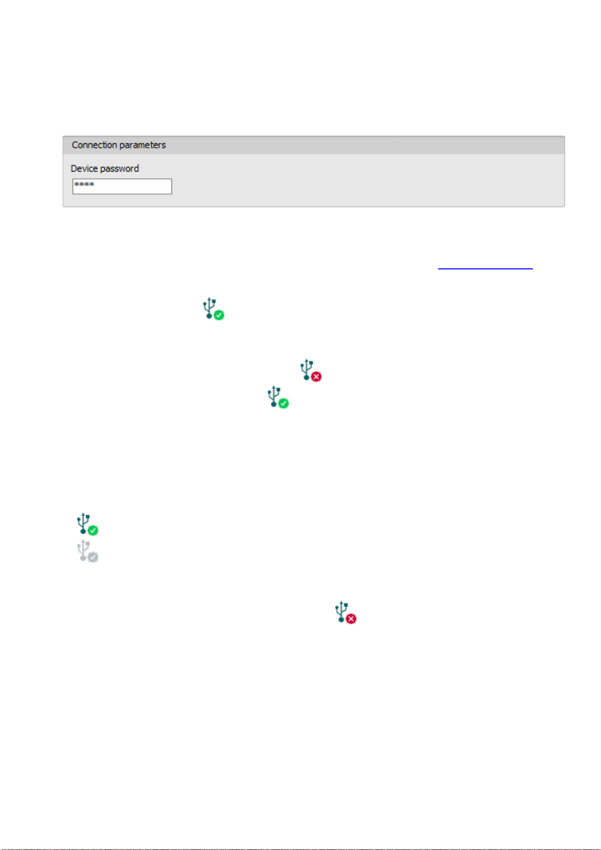
Device password: the security password of the device (default superadmin password: 1234).
Save the password: in case that you have provided the data necessary for connecting to the
device here in the “Connection parameters” section, and you enable this option, the program will
also save the entered password in the device register, when you initiate a connection to the device.

15
Connecting to the device through the cloud:
Select the “Cloud” option in the “Connection type” menu.
If you have already registered the device in the "Device register" menu, select the device
you want to connect to from the "Device Name" drop-down menu. Otherwise, you can
either enter the data needed for connecting, in the corresponding fields, which will be
recorded automatically in the device register using the entered device ID as the device
name, when you start connecting to the device. For this, select the server from the “Cloud”
drop-down menu, enter the identifier of the device in the “Device ID” field, and the device
password in the “Device password” field.
Entering the device password.
oSuper administrator permission: full access to all settings. (Default password: 1234).
oAdministrator permission: can only access settings enabled by the superadmin.
You can configure the admin password separately (see chapter “Connection type”).
oConnecting remotely without a password is not possible.
If cloud usage is enabled in the settings of the given device, the device keeps continuous
connection with the cloud server. In this case skip the SMS sending process mentioned
below. Cloud usage can be enabled in the “General” settings menu. If cloud usage is
disabled, the device will not keep continuous connection with the cloud, it will only connect
upon request. Therefore, if this is the case, before trying to connect remotely to the device,
the request for connecting to the server should be sent by SMS to the phone number of the
SIM card installed into the device. The device accepts the request for connecting to the
cloud server from the configured and authorized user phone numbers.
If the connecting request is sent from an unauthorized user phone number, or a number
which is not configured in the device, the device password should be added in themessage
using the “PWD” parameter, as specified below. Commands sent from unauthorized phone
numbers with a missing device password or a wrong password, will be ignored by the
device and it will not send any reply to these numbers.
The request command for connecting to the server is: CONNECT,PWD=device password#
Using the “PWD” parameter is optional, according to the following:
PWD: the device password can be specified using this parameter. The superadmin and admin
passwords are both accepted (default superadmin password: 1234). The PWD is an optional
parameter which should be used only when sending commands from phone numbers which are
not configured in the device, or from ones which are configured, but for which other than the
"Accept call and don’t request password" option is assigned in the “Incoming call
management”section –such phone numbers are considered unauthorized, therefore in this case
the password is required).
Example on the usage of the command mentioned above:
When sending from an authorized phone number: CONNECT#
When sending from an unauthorized phone number: CONNECT,PWD=1234#
Send the mentioned request command for connecting to the cloud by SMS to the phone number
of the SIM card installed in the device, and wait for the device’s reply. As soon as the device
successfully connects to the cloud, it will send the following reply:
Connected to (IP address:port number)
ID=(device identifier)

16
If cloud usage is disabled in the device settings, the device remains connected to the cloud
for 10 minutes only and thereafter in case of inactivity it disconnects automatically. Therefore, you
have 10 minutes to connect to the device after it sends the reply message.
If you receive no message from the device within 1 or 2 minutes, please make sure that the
settings are correct and that the circumstances of sending the request for connecting satisfy the
conditions mentioned above.
Possible error messages:
Missing APN
The APN is not configured.
Network connection error
The device is unable to connect to the Internet due to an
error, faulty settings, or missing Internet service.
If the APN settings are not configured in the device, or if they are wrong, you can configure this
using the following SMS commands. It is also possible to configure the cloud settings, but normally
the factory default values are configured for this.
SMS command
Specification
APN=APN,PWD=device password#
Configuring the APN
APN=APN,username,password,PWD=device password#
Configuring the APN along with
the username and password
belonging to it
CONNECT=server address:port nr,PWD=device password#
Configuring the cloud server
address and port number, then
connecting to the server
Example on the usage of the commands mentioned above:
APN=internet,PWD=1234#
APN=net,guest,guest,PWD=1234#
CONNECT=54.75.242.103:2020,PWD=1234#
Wait for the device’s reply. After it has confirmed that it has connected to the cloud, continue with
the next step.
Click on the “Connect” button and wait for the connection to establish. The process
of connecting may take a few seconds.
The connection status is indicated by the status icon in the top left corner of the program
window:
disconnected (green)
connected (gray)
After connecting using the valid password, you can configure the device, change settings,
download event logs, monitor system status and perform controls.
To disconnect from the device, click on the “Disconnect” button.

17
4.2.4 Remote connecting to devices via peer-to-peer connection
This connection type can only be used in aprivate APN, or through a virtual private network
(VPN) connected to the given private APN. In case of using a private APN, sending and
receiving data between the SIM cards in the given APN should be enabled. The SIM card
installed in the Pager4 device you wish to connect remotely to, should have a static IP
address and should be part of the given private APN, respectively VPN, just like the
computer from which you wish to connect to the device. If the computer is not part of the
given private APN through VPN, then you can connect to the device trough a mobile
Internet stick connected to the computer, in which you have to use a SIM card that is part
of the given private APN. Also, the APN settings should be configured in the device you
wish to connect to. These settings are available in the “General” settings menu.
*For connecting directly to the WiFi product model from outside the local network,
configuring port forwarding is required in your router, and the static WAN IP address of the
router should be used in the software. The device uses port 6789 and UDP protocol.
Otherwise, you can only access the device in the local network using its local IP address.
With this connection type, a direct (peer-to-peer) connection will be established between the
device and the Pager4 programming software.
The “System logs” option of the programming software cannot be used in case of remote
connection over the Internet.
Device name: from this drop-down menu, you can select the device you want to connect to, if you
have already added the contact details of the given device in the “Device register” menu.
Network: the name of the network used for connecting to the device. The program contains
a built-in network name “Peer-to-peer”, which can be used as the default. If needed, you can add
further network names in the “Server register” menu, which you can use to organize your devices
(e.g. you can configure a different network name for the local and the remote connections of your
WiFi devices).
Device IP address: the static IP address of the device you want to connect to. You can read the
device IP address of the given device from the “IP address” section in the “Status monitoring”
menu, via USB connection.
Device password: the security password of the device (default superadmin password: 1234).
Save the password: in case that you have provided the data necessary for connecting to the
device here in the “Connection parameters” section, and you enable this option, the program will
also save the entered password in the device register, when you initiate a connection to the device.

18
Connecting to the device through peer-to-peer connection:
Select the “Peer-to-peer” option in the “Connection type” menu.
If you have already registered the device in the "Device register" menu, select the device
you want to connect to from the "Device Name" drop-down menu. Otherwise, you can
either enter the data needed for connecting, in the corresponding fields, which will be
recorded automatically in the device register using the entered device ID as the device
name, when you start connecting to the device. For this, select the network from the
“Network” drop-down menu, enter the IP address of the device in the “Device IP address”
field, and the device password in the “Device password” field. *For the WiFi product model
you have to use the WAN IP address of the router to which the device is connected, if you
want to connect to the device from outside the local network.
Entering the device password.
oSuper administrator permission: full access to all settings. (Default password: 1234).
oAdministrator permission: can only access settings enabled by the superadmin.
You can configure the admin password separately (see chapter “Connection type”).
oConnecting remotely without a password is not possible.
Click on the “Connect” button.
The connection status is indicated by the status icon in the top left corner of the program
window:
disconnected (green)
connected (gray)
After connecting using the valid password, you can configure the device, change settings,
download event logs, monitor system status and perform controls.
To disconnect from the device, click on the “Disconnect” button.

19
4.2.5 Remote connecting to devices which are using the TEX protocol
This connection type can be used if the Pager4 device you want to access remotely has
been configured to communicate with the given server using the TEX protocol. This is an
early custom TELL protocol which is supported by the Pager4 device in order to be able to
communicate with the older TEX-MVP and TEX BASE/PRO servers. Therefore, this
connection type should be used basically to connect to the device via these servers.
However, for compatibility with the old TEX communicators, the TELLMon receiver and the
MVP.next server also support the TEX protocol. Therefore, still this connection type should
be used if the device is connected to a TELLMon receiver or an MVP.next server, and it has
been configured to communicate with the given server or receiver using the TEX protocol
for some reason.
Further details on the remote access of devices via the MVP.next server you can find in
chapter “Server register / Remote access of devices via the MVP.next server”.
With this connection type, connection between the device and the Pager4 programming software
can be established through the server/receiver on which the device is online.
The “System logs” option of the programming software cannot be used in case of a remote
connection over the Internet.
Device name: from this drop-down menu, you can select the device you want to connect to, if you
have already added the contact details of the given device in the “Device register” menu.
Server/Receiver: the name of the server or receiver where the device is connected. The server
or receiver contact details should be recorded in advance in the “Server register” menu.
TEX group ID: the CMS identifier of the Pager4 to which you want to connect to. The TEX group
ID can be configured in the device settings. Its format is: FFF (3 hexadecimal characters).
TEX device ID: the TEX identifier of the Pager4 to which you want to connect to. The TEX
identifier can be configured in the device settings. Its format is: FFF (3 hexadecimal characters).
Device password: the security password of the device (default superadmin password: 1234).
Save the password: in case that you have provided the data necessary for connecting to the
device here in the “Connection parameters” section, and you enable this option, the program will
also save the entered password in the device register, when you initiate a connection to the device.
Connecting to the device through a server/receiver which uses the TEX protocol:
Select the “TEX protocol” option in the “Connection type” menu.
If you have already registered the device in the "Device register" menu, select the device
you want to connect to from the "Device Name" drop-down menu. Otherwise, you can
either enter the data needed for connecting, in the corresponding fields, which will be
recorded automatically in the device register using the entered device ID as the device
name, when you start connecting to the device. For this, select the server from the
“Server/Receiver” drop-down menu, where the device is connected, enter the
CMS identifier in the “TEX group ID” field, the TEX identifier of the device in the
“TEX device ID” field, and the device password in the “Device password” field. The server
or receiver contact details should be recorded in advance in the “Server register” menu.

20
Entering the device password.
oSuper administrator permission: full access to all settings. (Default password: 1234).
oAdministrator permission: can only access settings enabled by the superadmin.
You can configure the admin password separately (see chapter “Connection type”).
oConnecting remotely without a password is not possible.
Click the “Connect” button.
The connection status is indicated by the status icon in the top left corner of the program
window:
disconnected (green)
connected (grey)
After connecting using the valid password, you can configure the device, change settings,
download event logs, monitor system status and perform controls.
To disconnect from the device, click on the “Disconnect” button.
4.2.6 Remote connecting to devices which are using the TELLMon protocol
This connection type can be used if the Pager4 device you want to access remotely is
connected to a TELLMon receiver or an MVP.next server, and it has been configured to
communicate with the given server or receiver using the TELLMon protocol.
Further details on the remote access of devices via the MVP.next server you can find in
chapter “Server register / Remote access of devices via the MVP.next server”.
With this connection type, connection between the device and the Pager4 programming software
can be established through the receiver on which the device is online.
The “System logs” option of the programming software cannot be used in case of remote
connection over the Internet.
Device name: from this drop-down menu, you can select the device you want to connect to, if you
have already added the contact details of the given device in the “Device register” menu.
Server/Receiver: the name of the server or receiver where the device is connected. The server
or receiver contact details should be recorded in advance in the “Server register” menu.
Device ID: the device identifier of the Pager4 device to which you want to connect to.
The device identifier is unique, burned-in during production, and thereby it cannot be changed.
The device ID format is: FF:FF:FF:FF:FF:FF (6x2 hexadecimal characters).
You can read the device ID of the given device from the “Device ID” section in the “Status
monitoring” menu, via USB connection, or from the user interface of the server or receiver.
Device password: the security password of the device (default superadmin password: 1234).
Save the password: in case that you have provided the data necessary for connecting to the
device here in the “Connection parameters” section, and you enable this option, the program will
also save the entered password in the device register, when you initiate a connection to the device.
Other manuals for Pager4 PRO Series
2
This manual suits for next models
25
Table of contents
Other tell Cell Phone manuals


