tell GSM Gate Control Pro 20 User guide

GSM Gate Control Pro 20
GSM Gate Control Pro 1000
INSTALLATION AND APPLICATION MANUAL
for module version v2.00.2532 and newer
Document version: 1.21 24.08.2017
► Features:
Control of outputs over the internet
using smartphone application
Control of outputs by free phone calls
using caller identification
5 different control modes
4 NO/NC inputs, 2 NO relay outputs
50 configurable access templates
Configurable holidays
Automatic timed controls
20 and 1000 user variant
Reports the status of the 4 contact
inputs by e-mail, SMS or GSM call
Stores the latest 1200 events in log
memory
Programmable via USB, internet
and smartphone application
► Application area:
Control of garage doors, gates,
barriers, electric devices
Reporting the state of error outputs
or switches

2
Table of contents
1General operation of the GSM Gate Control Pro...................................................................3
1.1 Data traffic.....................................................................................................................3
1.2 Operation of the contact inputs......................................................................................4
2Processing of personal data ..................................................................................................4
2.1 Responsibility of Manufacturer......................................................................................5
3Connecting the terminals and putting into operation..............................................................5
3.1 Under Voltage Lock Out (UVLO) function .....................................................................5
3.2 Input wiring....................................................................................................................6
3.3 Output wiring.................................................................................................................6
3.4 Connections ..................................................................................................................6
3.4.1 Wiring diagram......................................................................................................7
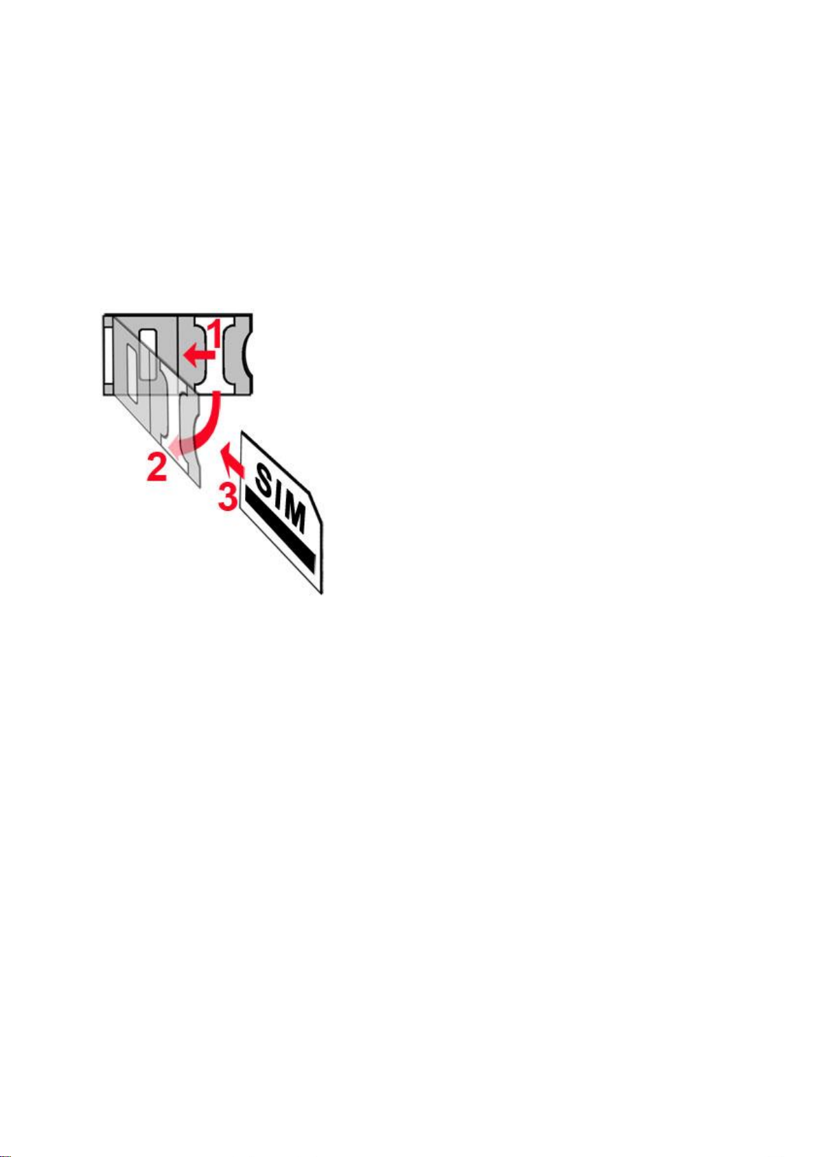
3.5 SIM card socket.............................................................................................................8
3.6 Connecting the antenna ................................................................................................8
3.7 Installation.....................................................................................................................8
3.8 Putting into operation ....................................................................................................9
3.9 LED signals...................................................................................................................9
3.10 Technical specification..................................................................................................9
4Configuring the Gate Control Pro module............................................................................10
4.1 The user interface and configuration options of the software:.....................................10
4.2 Configuring by computer via USB ...............................................................................11
4.3 Configuring by computer over the Internet ..................................................................11
4.3.1 Adding a client identifier for the programming software......................................12
4.3.2 Managing SIM identifiers ....................................................................................13
4.3.3 Steps of remote programming ............................................................................14
4.3.4 QR code..............................................................................................................14
5How to use the Gate Control Pro programming software ....................................................15
5.1 Module status..............................................................................................................15
5.2 Event log.....................................................................................................................16
5.3 Settings.......................................................................................................................17
5.3.1 Identification........................................................................................................18
5.3.2 Internet access....................................................................................................18
5.3.3 Call durations......................................................................................................19
5.3.4 Servers ...............................................................................................................19
5.3.5 Test report ..........................................................................................................19
5.3.6 Outgoing e-mail account.....................................................................................20
5.3.7 Cameras.............................................................................................................20
5.3.8 E-mail report .......................................................................................................21
5.3.9 Miscellaneous settings........................................................................................22
5.4 Inputs and outputs.......................................................................................................23
5.4.1 Inputs / Events....................................................................................................23
5.4.2 Control modes.....................................................................................................25
5.5 Customization..............................................................................................................28
5.6 Admin functions...........................................................................................................29
5.6.1 Global rule ..........................................................................................................30
5.7 Automatic timed control...............................................................................................31
5.8 Access templates........................................................................................................33
5.9 Users...........................................................................................................................34
5.10 Holidays ......................................................................................................................39
6Replacing the SIM card .......................................................................................................40
7Contents of the package......................................................................................................40

3
Dear Customer,
Thank you for purchasing this product. This manual includes important information and
instructions regarding the product. Please read this manual before using the product.
The latest version of the product’s programming software and manuals are available
on the manufacturer’s website at
https://tell.hu/en/products/gsm-automation/gsm-gate-control-pro
1 General operation of the GSM Gate Control Pro
The GSM Gate Control Pro module was basically designed for control of electric gates and
barriers, however it can be used to control other devices as well. Controlling can be
performed according to the configured control mode by making a phone call to the SIM card
installed into the module and/or over the internet, using the smartphone application. During
the installation you can choose out of 5 control modes the one which is appropriate for your
application. In case of controlling by call, the system uses caller identification to identify the
caller/user. Since to identify the caller and perform the control is enough to identify the caller
ID, the system rejects the call, thereby the call will be free of charge. However, it is possible
that the GSM service provider applies call set-up fee top rejected calls (this is operator-
dependent, please ask your GSM service provider). When calling from an authorized phone
number, the module rejects the call and activates the appropriate output(s), and stores the
event in the event log. When controlling by smartphone application, the system identifies the
user by the identifier of the smart device, which can be read from the Gate Control
smartphone application.
Depending on the variant, the system supports up to 20 or 1000 users to which different
permissions and access periods, as well as custom access rules can be assigned.
The access periods can be configured by access templates which can be assigned to users.
The system will accept control commands from the given user within the access period and
will reject them when out of the period.
The services to be activated on the SIM card installed into the Gate Control Pro device
should be chosen according to which services of the device you wish to use. For usage with
the smartphone application and for the functions that use e-mail sending mobile internet
service is necessary. The functions that use SMS sending need SMS service and the ones
that use calls require GSM voice call service. For accessing the Internet the SIM card
should use a public APN.
Attention! If you do not connect the gate’s position limit switch to the Gate Control Pro
device, the system will not have information about the open/closed state of the gate. In this
case the alternative control options (remote controller, pushbutton, etc.) used parallel with
the module may cause malfunctions, since the module will not be notified about opening and
closing the gate with e.g. a remote controller.
1.1 Data traffic
The expected data traffic of the SIM card installed into the Gate Control Pro device at
minimal usage may reach even up to ~20 MB per month. The data traffic rate depends on
the frequency of use, the stability of the mobile network and the used services. The services
using data traffic, such as control by smartphone application, remote programming, remote
download of event logs, remote firmware update, sending of emails and reports, all
contribute to the increase of the SIM card’s data traffic. The extent of the data traffic
increase depends on how frequent and for how long the mentioned services are used.
Depending on the usage, the data traffic may reach the multiple of the amount mentioned
for minimal usage.

4
1.2 Operation of the contact inputs
The module has 4 configurable NO/NC contact inputs. By activating the inputs, notifications
can be sent by SMS or call up to 4 phone numbers, or by e-mail, according to the settings.
This function can be used for e.g. sending notification by SMS or email about the state of
tamper or other switches, control panel error or other outputs. Notification by call is not
available if the “Online mode” is enabled, that is if you wish to control the system over the
internet as well or use the services that require continuous internet connection.
Input IN1 is assigned by factory default to doorbell function, which means that if the system
is used with smartphone application and input IN1 is activated, a ringing notification will be
sent to the users’ smart devices for which this option (permission) is enabled. Permissions
can be configured at user setting. This function uses Push notification service.
Input IN2 is assigned by factory default to failure notification function, which means that if
the system is used with smartphone application and input IN2 is activated, the system sends
“Technical or device failure” notification to the users’ smart devices by Push notification
service.
The properties of the functions assigned to the inputs mentioned above (e.g. message,
assigning to other input) cannot be changed.
Inputs IN3 and IN4 are assigned by factory default to gate position limit failure notification
function. In case of using control mode 1 or 2, the position limit switch of gate “A” should be
connected to input IN3, while the position limit switch of gate “B” should be connected to
input IN4. In case of control modes 3, 4 and 5 the gate’s position limit switch should be
connected to input IN3. If the position limit switch is connected, the device can send
notifications via Push and/or SMS when the gate fails to open or close.
2 Processing of personal data
The users can control the system with the help of their usernames, phone numbers and/or
smartphone application identifiers, therefore, in order to operate the system it is necessary
that the users who wish to use the system to provide their names (usernames) and phone
numbers (hereinafter referred to as personal data) to the system administrators defined in
the device, who will introduce these personal data into the system. The users can provide
the personal data directly, or indirectly with the help of a registration request sent using the
smartphone application used to control the system. When sending a registration request, the
smartphone application identifier is automatically forwarded.
Users’ consent to processing their personal data shall be deemed to be given on the basis
of their clear and explicit consent by providing voluntarily the personal data in a direct or
indirect way. The purpose of personal data processing is to ensure access to the system
and thus to provide permission of use for users who wish to use the system. The system
stores the personal data in the device’s memory. The personal data are not accessible for
third party, only for the system operator/installer and the assigned system administrators.
The assigned system administrators are obliged to treat the personal data confidentially,
in line with the legislative provisions, and shall not disclose the data to third party.

5
2.1 Responsibility of Manufacturer
The Manufacturer takes any kind of responsibility for and in connection with the functionality
and use of the system –including proper use of hardware and software –according to the
relevant provisions of law. The Manufacturer takes no responsibility for damage resulting
from:
- the user having lost the device for controlling the system, or this device or his personal
data mentioned above having been stolen, thus enabling an unauthorized person to
have access to the system;
- the user having intentionally, in good faith, directly or indirectly given his personal data or
the device suitable for controlling the system to a third person.
3 Connecting the terminals and putting into operation
3.1 Under Voltage Lock Out (UVLO) function
The product is provided with built-in automatic power disconnection (Under
Voltage Lock Out) function. Depending on the product type, if the supply voltage
drops below 8.4…8.2V, the module turns off automatically and it turns back on
when the supply voltage is at least 11.2…11.4V.
The minimum supply voltage level required to turn the module on is 11.2…11.4V!
After turned on with supply voltage higher than 11.2…11.4V, the module can operate
stably even at lower supply voltage, but not lower than 8.4…8.2V.
If the module is powered from a power supply provided with a backup battery and there is
no other electrical load on the battery when charging fails (e.g. in case of a power cut), while
the battery discharges, the module turns off automatically at 8.4…8.2V voltage level.
Thereafter, if the battery is in good condition, it can regenerate and can reach the terminal
voltage of 11.2…11.4V where the module turns back on, then the battery may discharge
again below 8.4…8.2V. This may result a continuous switching on and off cycle that lasts
until the battery can no longer regenerate to the 11.2…11.4V voltage level. If this
phenomenon occurs, the battery is flat and it should be replaced.

6
3.2 Input wiring
For the inputs, the normally closed or normally open dry contact should be connected
between the given input (IN1…IN4) and the negative of the power input (V-).
If a normally open activating dry contact is used, choose the NO (normally open) option at
the given input’s settings. In this case the input becomes activated and notification sending
by SMS, e-mail or call is initiated when the given input (IN1…IN4) and the V- terminal is
shorted.
If a normally closed activating dry contact is used, choose the NC (normally closed) option
at the given input’s settings. In this case the input becomes activated and notification
sending by SMS, e-mail or call is initiated when shorting between the given input (IN1…IN4)
and the V- terminal is removed.
Connecting the gate position limit switch:
When using control mode 1 or 2 with a single gate, the position limit switch of the gate
controlled by output OUT1 should be connected to input IN3. If two gates are controlled, the
position limit switch of the gate controlled by output OUT2 should be connected to input IN4.
For control modes 3, 4 and 5 the position limit switch of the gate should be connected to
input IN3.
3.3 Output wiring
Connecting the outputs should be done according to the configured control mode.
The default state of the outputs for given control modes is the following:
For control modes 1, 2, 4, 5:
OUT1: normally open dry relay contact (N.O.)
OUT2: normally open dry relay contact (N.O.)
For control mode 3:
OUT1: normally open dry relay contact (N.O.)
OUT2: normally closed dry relay contact (N.C.)
The normally open (N.O.) output provides open contact by default and closed contact upon
control. The normally closed (N.C.) output provides closed contact by default and open
contact upon control. The outputs provide dry (potential free) relay contacts.
3.4 Connections
Attention! Do NOT connect the metallic parts of the GSM antenna connector or the
module’s terminals directly or indirectly to the protective ground, because this may
damage the module!

7
3.4.1 Wiring diagram
System terminal inputs and outputs:
V+ Supply voltage 9-30 VAC/DC (min. 500mA)
V- Supply voltage negative (if DC)
IN1 Dry contact input 1
IN2 Dry contact input 2
IN3 Dry contact input 3
IN4 Dry contact input 4
OUT1Relay output 1 (normally open dry contact)
OUT2Relay output 2 (normally open dry contact)
Wiring example for control modes 1, 2, 4, and 5:
Wiring example for control mode 3:
The example shows wiring of inputs
IN1 and IN2 when configured to
normally open, and when inputs IN3
and IN4 are configured to normally
closed.
The example shows wiring of inputs
IN1 and IN2 when configured to
normally open, and when inputs IN3
and IN4 are configured to normally
closed.
When using control mode 3, output
OUT1 is used for control while OUT2 is
used with normally closed state to
interrupt the photocell detection circuit,
thus making it possible to keep the
gate/barrier open for the configured
period of time.

8
3.5 SIM card socket
The SIM card socket can be accessed by removing the cover of the aperture found on the
module enclosure. The cover can be removed by pressing it with your fingernail towards the
LED at the end where the gap is and then pulling it outwards. Insert the SIM card in the
socket. The services to be activated on the SIM card installed into the Gate Control Pro
device should be chosen according to which services of the device you wish to use. For
usage with the smartphone application and for the functions that use e-mail sending mobile
internet service is necessary. The functions that use SMS sending need SMS service and
the ones that use calls require GSM voice call service. For accessing the Internet the SIM
card should use a public APN.
Installing the SIM card:
1. pull the metal security lock of the SIM socket
towards the LED until it clicks
2. reach under the metallic security lock with your
fingernail and pull it outwards to open the socket
3. slide the SIM card into the opened part with the
contacts facing down, as shown in the figure
Close back the opened part together with the SIM
card
Press down carefully the metallic security lock
and pull it towards the side of the enclosure until it
clicks.
3.6 Connecting the antenna
Connect the GSM antenna to the FME-M socket. The module comes with an antenna
which provides good transmission under normal reception circumstances. In case of
experiencing signal strength problems or/and wave interference (fading), use another
(directed) type of antenna or find a more suitable mounting place for the antenna.
3.7 Installation
Please check the environment before installing:
Verify the GSM signal strength with your mobile phone. It may happen that the
signal strength is not sufficient in the desired mounting place. In this case the
planned installation place can be changed before mounting the device.
Do not mount the unit in places where it could be affected by strong
electromagnetic disturbances (e.g. in the vicinity of electric motors, high voltage,
etc.).
Do not mount the unit in wet places or places with high degree of humidity.

9
3.8 Putting into operation
Disable voicemail and notification in SMS about missed calls on the SIM card
installed into the module.
The module can handle the SIM card’s PIN code. If you wish to use the
PIN code management, configure the SIM card’s PIN code in the programming
software at the “Settings” section. Otherwise disable PIN code request on the
SIM card.
Enable caller identification service on the SIM card at the GSM service
provider (this service might not be enabled by default, please check). To enable this
service, install the SIM card into a mobile phone and call the customer service of the
card’s GSM service provider and enable the service in the menu, or visit one of the
service provider’s personal customer services and ask to enable this service on the
SIM card.
Check the SIM card to be installed correctly into the module.
Check the GSM antenna to be connected correctly to the module.
Check the wires to be connected as instructed in the wiring diagram.
You can power up the device (9-30 VAC/DC). Make sure that the power source is
sufficient for the operation of the Gate Control Pro module. The quiescent
current of the Gate Control Pro module is 120mA, however it may increase up to
500mA during communication and relay control. If the used power source is not
sufficient for the operation of the module, this may cause malfunctions. For such cases
230VAC/12VDC-1A power adapter can be ordered separately from the manufacturer.
3.9 LED signals
Slowly flashing green
Normal operation,
connected to GSM network
Flashing red
GSM service unavailable
or system startup/restart in progress
Permanent red
SIM card error
3.10 Technical specification
Supply voltage range: 9-30 VAC/DC
Nominal current consumption: 120mA
Highest current consumption: 500mA @ 12VDC, 250mA @ 24VDC
Operating temperature: -20ºC - +70ºC
Transmission frequency: GSM 900/1800 MHz
Highest load supported on outputs: 1A @ 24VAC/DC
GSM phone model: Simcom SIM800F
Dimensions: 84 x 72 x 32mm
Weight: 200g (packed: 300g)

10
4 Configuring the Gate Control Pro module
The Gate Control Pro module can be configured in the following ways:
by computer via USB, using the programming software
by computer over the Internet, using the programming software*
by the smartphone application over the Internet (only settings regarding the user
management are available)*
You can read more about configuring by the smartphone application in the user’s
manual of the application.
*The function marked with * character are only available when a SIM card with mobile
internet access is installed in the Gate Control Pro device and the server access is
configured correctly so that the device has online connection with the server. If you wish to
use the system’s Internet-based services, it is necessary to configure in advance the
settings needed for accessing the Internet. You can learn more about these settings in the
“Internet access” and “Servers” paragraphs.
The Gate Control Pro programming software is compatible with Windows operating
systems only.
Compatibility: Windows 8.x 32/64bit, Windows 7 32/64bit, Windows XP 32/64bit.
Installing the programming software: open the software setup application and follow the
instructions of the installation wizard to complete the installation.
The latest version of the programming software can be downloaded from the manufacturer’s
website (https://tell.hu/en/products/gsm-automation/gsm-gate-control-pro).
4.1 The user interface and configuration options of the software:
The user interface language can be selected from the language
selection drop-down menu placed at the bottom left part of the
program window.
The user interface skin can be changed using the “Skin”
dropdown-menu placed at the bottom left part of the program
window, where you can choose out of multiple appearance
themes.
Context-sensitive help:
On the right side of the program window a context-sensitive help can be found. If you click
on any of the settings fields within the program window, you will get brief information about
the given option or setting in the help window. The content of the help window can be
scrolled up and down using scrollbar placed on the right side of the help window. When
clicking on the “Detailed help” button, a new help window opens with more details. The size
and position of the help window can be changed as desired.
You can hide and recall the help window by clicking on the thin vertical reddish button
placed at the middle on the left side of the help window.
The software saves the changes related to appearance upon closing and applies the saved
settings when reopened.

11
4.2 Configuring by computer via USB
To start programming the Gate Control Pro module, follow the instructions below:
Open the Gate Control Pro programming software.
Power up the Gate Control Pro module and connect it to the computer using a USB
A-B cable.
The software connects to the Gate Control Pro module using standard HID driver
which is integrated in Windows operating systems, thus there is no need to install
special USB drivers. When the Gate Control Pro module is connected to USB for the
very first time, the Windows operating system installs the drivers automatically.
The system does not use a security password for connecting via USB. After
connecting the USB cable, the software connects automatically to the Gate Control
Pro module.
Connection status is indicated by the USB status icon placed on the “Connection” tab:
: USB disconnected (grey)
: connected via USB (green)
After the connection is established, the settings can be read and changed, the event
log can be downloaded and status information is also available.
4.3 Configuring by computer over the Internet
For connecting via the Internet, the SIM card installed into the Gate Control Pro
module should have Internet service and should also use public APN.
To connect to the module via the Internet, an intermediary server is also necessary, where
both the programming software and the module connects, through which this way the
connection can be established between the programming software and the module. The
manufacturer of the product provides a server for this purpose available 24 hours a day,
which can be used free of charge.
Remote programming by computer can be done using the Gate Control Pro programming
software (desktop application). In case of remote access, the programming software
connects to the Gate Control Pro module as a client application using user name and
password, therefore it is necessary to add beforehand a new client identifier via USB
connection and assign this identifier to the user whom you wish to give remote access.
Thereby practically any user may get remote access according to its permission level.

12
4.3.1 Adding a client identifier for the programming software
Open the Gate Control Pro programming software.
Power up the Gate Control Pro module and connect it to the computer via USB.
If you wish to assign the client identifier to a new user, add the new user in the “Users”
menu, write the changes to the module, then edit the given user’s settings again. If you
wish to add the client identifier to a user which already exists in the system, read the
user list from the module in the “Users” menu, then edit the user to which you wish to
add the client identifier.
To add the new client identifier click on the “New” button in the “Client identifiers”
section of the user’s editing window. In Enter a name for the programming software in
the “Name”field of the client identifier window, then select the “Password for remote
programming” option in the “Client identifier” section and enter the new password
here. The software will ask for this password (and the user name of the given user)
when the given user wants to connect to the Gate Control Pro module for remote
programming. Click on the “Write” button to save the changes.
Thereby a client identifier and password can be assigned to any of the users, thus
providing remote access with the programming software. The user signing in remotely
via the programming software can only access the settings and options according to its
permission level.
Remote access levels:
With Super admin permission: full access, can access all settings
With Admin permission: can access everything except “Settings” and
“Customization” menus
With User permission: has no remote access permission, cannot access
anything.
The permission level can be selected in the “Permission” drop-down menu in the user
editing window.

13
4.3.2 Managing SIM identifiers
For remote programming over the Internet it is necessary to provide the identifier (ICCID) of
the SIM card installed into the Gate Control Pro module you wish to configure. To make
remote programming of multiple Gate Control Pro devices easier, the software stores all
entered SIM identifiers and makes it possible to select a formerly used identifier from the
drop-down menu.
You can name the stored SIM identifiers at will in the SIM identifier editor window, which you
can open by clicking on the “SIM identifiers” button.
In the SIM identifier editor window you can add new SIM identifiers, delete existing ones and
change the name and identifier number of existing ones.
Adding a new SIM identifier
To add a new SIM identifier click on the “New” button, enter the desired name for the new
identifier in the “Name” field and the identifier itself in the “SIM identifier” field, then click
“OK” to store.
Changing a SIM identifier
To change an existing SIM identifier, click in the list on the identifier to be changed, then
click on the “Edit” button. Change the desired data, then click “OK” to save the changes.
Deleting a SIM identifier
To delete an existing SIM identifier, click in the list on the identifier to be deleted, then click
on the “Delete” button.

14
4.3.3 Steps of remote programming
To start remote programming of the Gate Control Pro module, follow the instructions below:
To establish the connection, go to the programming software’s “Connection” menu,
select the Gate Control Pro module you wish to configure from the “SIM identifier”
drop-down menu, or enter the identifier of the SIM card installed into the module, enter
the server IP address (54.75.242.103), the port number (2016), your user name
registered in the Gate Control Pro module and the remote programming (client)
password assigned to your user name, then click on the “Connect” button. You
can find the SIM identifier printed onto the SIM card or you can read it from the “SIM
identifier” field of the “Module status” menu when the Gate Control Pro module is
connected via USB.
Connection status is indicated by the Internet status icon placed on the “Connection”
tab:
: disconnected (grey)
: connected via the Internet (green)
After connecting successfully, the settings can be read and changed, the event log can
be downloaded and the status information can be viewed just like when connected via
USB. Of course, data downloading and uploading takes longer over the Internet
connection than via USB.
To close the connection click on the “Disconnect” button.
4.3.4 QR code
The QR code found in the “Connection” menu is used to transfer the connection data easily
to the smart phone application. To generate a QR code, connect the Gate Control Pro
module to the computer via USB. The software reads the identifier of the SIM card installed
into the connected module automatically and prepares the QR code that includes the three
connection data (server IP address, port number and SIM identifier).
You can read the QR code with your smart device directly from the screen, or from a printed
sheet if it has been printed. To print the QR code click on the QR code using the right
mouse button, save to file or copy to clipboard, then paste into a new document (e.g. Word)
where you can also add usage information, and print from there.

15
5 How to use the Gate Control Pro programming software
5.1 Module status
The module status menu provides information on the actual system status.
SIM identifier: the identifier of the SIM card inserted into the Gate Control Pro module
Name: the module’s type
Hardware version: the module’s hardware version
Firmware version: a module’s firmware version
System time: the system date and time
Uptime: the uptime since powered up
GSM uptime: the uptime since the last GSM network connection
IP uptime: the uptime since the last internet connection
GSM operator: the name of the GSM operator used actually
GSM signal: actual GSM signal level
Lowest GSM signal: the lowest GSM signal measured since the last GSM connection
IP address: the module’s actual IP address
Supply voltage: value of measured supply voltage in Volts
Lowest supply voltage: the lowest supply voltage value measured since powered up
Inputs (IN1…IN4): the actual status of the four contact inputs
Outputs (OUT1, OUT2): the actual status of the two relay outputs
Status messages: system status messages displayed during operation

16
5.2 Event log
The event log includes control events and input events recorded during operation.
Available options:
: read event log from the module
: export the read event log to file in CSV format
Reading the event log from the module:
When reading the event log, you can specify by filtering options the period and event type
you wish to download. It is also possible to filter by user name, but for this first it is
necessary to download the user’s list. If no filtering option is specified, the software
downloads the entire event log.

17
5.3 Settings
In the “Settings” menu you can configure the parameters related to the general operation of
the Gate Control Pro module.
Settings management:
The settings can be saved to file and loaded from file using the appropriate
function buttons.
Read settings from the module:
In order to apply the settings after changing, the settings should be written to the
module using the “Write” button.
Write settings to the module:
In order to apply the settings after changing, the settings should be written to the
module using the “Write” button.
Create full system backup:
You can create a full system backup after clicking on this button. The full system
backup includes all the settings, as well as users’ database, client identifiers,
templates and holidays. To create a full system backup click on the button, browse
the target folder, enter a filename and click on the “Start” button.
Restore system from backup:
To restore the system from backup, click on this button, select the backup file and
click on the “Start” button. This option is only available when connected via USB.
In case of connecting through the Internet, the connection would fail since all existing
users are erased when uploading the new data, thus the connected user too, so the user
would lock himself out of the system.

18
System time synchronization:
The system time should be synchronized only if connecting to the server is disabled,
else the time is synchronized automatically from the server. To synchronize the time,
click on the “Time synchronization” button. The software synchronizes the time to
the PC system time, therefore please check before proceeding if the PC system time is
correct.
Send test e-mail:
This button can be used to check if the e-mail sending function works. To send a test
e-mail, click on the button, enter the e-mail address or select one from the drop-down
menu and click on the “Send” button. If the test e-mail is not received, check the
“Internet access” and “Outgoing e-mail account” settings.
5.3.1 Identification
Device name: here you can give a name to your Gate Control Pro module, which name
will also be used in the reports.
Attention! The following characters should not be used: ~ ^ < > = ’ ” , | $ &
Phone number: enter the phone number of the SIM card inserted in the Gate Control Pro
module. This is used in the smartphone application for backup GSM calls and for SMS
sending during the smart device registration process.
PIN code: if you wish to use PIN code management, enter here the PIN code of the
SIM card installed into the module. Otherwise disable PIN code request on the SIM card.
If you have configured the wrong PIN code and therefore the module is unable to connect to
the GSM network, it might happen that the SIM card reaches the PUK code request stage.
In this case install the SIM card into a cellphone, unlock it by entering the PUK code and
correct the PIN code at the module’s settings.
5.3.2 Internet access
If you wish to use the Internet-based services of the system, it is necessary to configure the
settings needed for accessing the Internet, and it is also necessary to use a SIM card with
available mobile internet service in the Gate Control Pro module.
APN: the APN name necessary to connect to the internet. (ask for this at the GSM service
provider of the SIM card inserted in the Gate Control Pro module).
User name: necessary only if the GSM service provider provides this and requires its usage
for the given APN.
Password: necessary only if the GSM service provider provides this and requires its usage
for the given APN.

19
Online mode: The system can be configured to connect to the internet online
(continuously), or to connect only occasionally, when needed. For online connection
continuous mobile internet connection is needed, which results in larger data traffic.
If online mode is enabled, the following services will be available:
- smartphone application
- remote programming
- remote firmware update,
In turn, if online mode is enabled, the system is unable to initiate outgoing calls,
therefore the following call-based functions will be unavailable:
- notification by call upon activating an input
- callback option
If online mode is disabled, the following e-mail functions will still be available, because
they do not require continuous internet connection:
- e-mail sending upon activating an input
- e-mail reports
- test report by e-mail
5.3.3 Call durations
Incoming call duration: the time after which the system rejects the incoming calls can be
configured here in seconds. In case of entering value “0”, the system rejects the incoming
calls immediately after they are received.
Callback duration: the system is able to confirm an incoming control call by calling back the
given number. Callback option can be enabled separately for each user. With this setting it
can be configured how long the system should ring the user’s phone when calling back.
When this time expires, the system ends the call automatically. This option is not available
id “Online mode” is enabled!
5.3.4 Servers
If you wish to use the Internet-based services of the system (e-mail sending, remote
programming, remote firmware update, smartphone application), then it is necessary to
configure the availabilities of the Gate Control server(s).
The availabilities of the server provided free of charge by the manufacturer for this purpose
is the following:
Server address: 54.75.242.103
Server port: 2016
5.3.5 Test report
The system can send periodic test report by SMS and e-mail by the configured interval.
Phone number: enter the phone number to which you wish to receive test report by SMS.
E-mail address: enter the e-mail address to which you wish to receive test report. You can
enter multiple e-mail addresses separated by comma. If you wish to use the e-mailing
services of the system, it is necessary to configure the internet access and the outgoing e-
mail account settings.
Interval: the interval of test report sending specified in days.
Time of day: the time of day for test report sending.

20
5.3.6 Outgoing e-mail account
If you wish to use the e-mailing services of the system, it is necessary to configure the
outgoing e-mail account.
SMTP service - available options:
-Default: for sending e-mails, the system uses the Gmail account provided by the
manufacturer. In this case the system sends the notification e-mails and reports from the
following e-mail address:
-Gmail account: here you can configure a custom Gmail account to be used by the
system to send e-mails. In this case the system sends the notification e-mails and
reports from the e-mail address of the configured Gmail account.
When you finished configuring this option, use the “Send test e-mail” button to send a
test e-mail and check if the function works.
5.3.7 Cameras
You can add to the Gate Control Pro system the availabilities of at most 2 IP cameras
which support the ONVIF standard. The system makes available the images of the
configured IP cameras in the smartphone application. Permission for viewing the images
can be configured in the editing window of the users, for each user separately and per
camera.
Camera URL: the image link of the IP camera
Camera type: the image transfer mode supported by the IP camera:
- Stream: video, continuous content
- Picture: still picture
This function works only with cameras that support the ONVIF standard!
The manufacturer does not guarantee that the Gate Control Pro can be used with any
IP camera, therefore, still before purchasing the Gate Control Pro device, the
Gate Control smartphone application assures possibility to test the camera in advance and
make sure that your camera works properly with the Gate Control smartphone application
(further details are available in the user’s guide of the smartphone application).
The list of ONVIF cameras tested by the manufacturer is available at www.tell.hu at the
Gate Control Pro product’s downloads.
There are multiple methods to obtain the camera URLs. You can use the “ONVIF Detector”
software made by the manufacturer (available on the manufacturer’s website: www.tell.hu),
the “ONVIF Device Manager” software (http://sourceforge.net/projects/onvifdm), or the
camera’s technical manual.
In order to access the camera pictures from outside your local network it is
necessary to replace the local IP address and port in the URL obtained using the
ONVIF URL detector program with the external (WAN) IP address of your router and
the external port, and after this enter the modified URL in the Gate Control Pro
programming software and write this into the module settings.
This manual suits for next models
1
Table of contents
Other tell Control Unit manuals
Popular Control Unit manuals by other brands

AUTOTECH
AUTOTECH R2010-D Installation and programming manual

ADLINK Technology
ADLINK Technology ND-6021 user guide

Siemens
Siemens SIMATIC IM 178-4 manual

DMP Electronics
DMP Electronics 738ZplusINT installation guide

Tormatic
Tormatic T75 DES Assembly and operating instructions

W.E.ST.
W.E.ST. POS-124-U-PFN Technical documentation

Leviton
Leviton 73A00-3ZB Installation instructions and user guide

Wurth Elektronik
Wurth Elektronik Proteus-E user manual

Belimo
Belimo B2100VB-024 Technical documentation

GREAT PLAINS
GREAT PLAINS ElectriFly C-5 Nano manual

Festo
Festo CMGA-E1-PB Translation of the original instructions

ETC
ETC SmartModule 2 installation guide