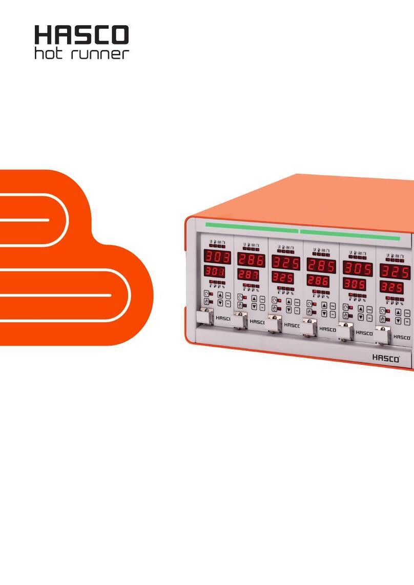
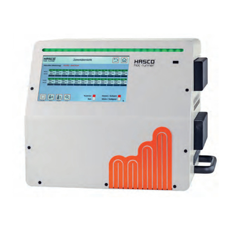
Hasco H1280 Series User manual

D / GB / F 07 / 19 HK
H1280/...
Multi-zone control unit
Operating instructions

Bedienungsanleitung H1280
HASCO hot runner 3
Foreword
Thank you for choosing a HASCO hot runner product.
These operating instructions are intended for everyone who works with HASCO hot runner technology and explain
how to safely handle HASCO hot runner products.
These operating instructions must be read carefully by personnel whenever a product is brought into operation for the
first time. They must always be readily available during operation.
The operating instructions form the basis for the safe handling of HASCO hot runner technology. The instructions and
information given here, and particularly the safety rules, must be followed under all circumstances.
The general safety regulations and accident prevention regulations at the location in question must always also be
observed by personnel.
The operating instructions contain illustrations which serve for a better understanding only. In addition, the scope of
delivery for special versions or the latest technical changes can lead to deviations from the actual version supplied.
With this edition, all previous versions lose their validity.
Read carefully prior to use
and keep for future reference.

4 HASCO hot runner
1 Introduction .................................................................................................................................... 6
1.1 Symbols used ........................................................................................................................... 6
1.2 Notations .................................................................................................................................. 6
2 Safety instructions ......................................................................................................................... 6
2.1 Intended use ............................................................................................................................ 6
2.2 Information for operators and users ......................................................................................... 6
3 Structure and functionality ........................................................................................................... 7
3.1 General information ................................................................................................................. 7
3.2 Structure ................................................................................................................................... 7
3.2.1 Display (1) ......................................................................................................................... 9
3.2.2 LED strip (3) ...................................................................................................................... 9
3.2.3 Power boards (13) ............................................................................................................ 9
3.2.4 Connections ...................................................................................................................... 9
3.2.4.1 USB connection (2) ...................................................................................................... 9
3.2.4.2 Ethernet connection(9) ................................................................................................. 9
3.2.4.3 RS485 connection (8) .................................................................................................. 9
3.2.4.4 Alarm contacts (7) ........................................................................................................ 9
3.2.4.5 Digital inputs (10) ......................................................................................................... 9
3.3 Identification marking on the controller .................................................................................. 10
3.3.1 Wiring of the plug systems .............................................................................................. 10
4 Commissioning ............................................................................................................................ 10
4.1 Electrical connection .............................................................................................................. 10
4.1.1 Mains electricity .............................................................................................................. 11
4.1.2 Connection to the mains electricity ................................................................................. 11
4.1.3 Connection of the mould ................................................................................................. 11
4.2 Operating and display concept .............................................................................................. 11
4.2.1 Main switch ..................................................................................................................... 11
4.2.2 Status display .................................................................................................................. 11
4.2.3 Operation ........................................................................................................................ 11
5 Start menu .................................................................................................................................... 12
5.1 Navigation bar ........................................................................................................................ 13
5.2 Selection of zones and groups for operation ......................................................................... 14
5.3 Navigation menu .................................................................................................................... 14
5.3.1 Setup ............................................................................................................................... 16
5.3.1.1 Quick start .................................................................................................................. 16
5.3.1.1.1 Groups ................................................................................................................. 16
5.3.1.1.2 Operating mode ................................................................................................... 16
5.3.1.1.3 Setpoint values .................................................................................................... 17
5.3.1.2 Monitoring .................................................................................................................. 18
5.3.1.2.1 Temperature monitoring ....................................................................................... 18
5.3.1.2.2 Sensor fracture monitoring................................................................................... 19
5.3.1.2.3 Residual current monitoring ................................................................................. 20
5.3.1.2.4 Output level monitoring ........................................................................................ 20
5.3.1.2.5 Heating current monitoring................................................................................... 21
5.3.1.3 Heating ....................................................................................................................... 21
5.3.1.4 Mould test ................................................................................................................... 22
5.3.1.5 Others ........................................................................................................................ 23
5.3.1.5.1 Sensor type .......................................................................................................... 23
5.3.1.5.2 Max. output level .................................................................................................. 23
5.3.2 Operation ........................................................................................................................ 24
5.3.2.1 Home view ................................................................................................................. 24
5.3.2.1.1 General presentation ........................................................................................... 24
5.3.2.1.2 Changing the setpoint value and output level ...................................................... 29
5.3.2.1.3 Activating the boost function ................................................................................ 29
5.3.2.1.4 Changing the operating mode ............................................................................. 30

Bedienungsanleitung H1280
HASCO hot runner 5
5.3.2.2 Diagnosis ................................................................................................................... 30
5.3.2.2.1 Faults ................................................................................................................... 30
5.3.2.2.2 Events .................................................................................................................. 30
5.3.2.2.3 Fault handling ...................................................................................................... 30
Warnings and alarms ............................................................................................................. 31
5.3.2.3 Plotter ......................................................................................................................... 33
5.3.2.4 Control ....................................................................................................................... 34
5.3.2.4.1 Control dynamics ................................................................................................. 34
5.3.2.4.2 Heating signal ...................................................................................................... 35
5.3.2.5 All parameters ............................................................................................................ 36
5.3.3 Settings ........................................................................................................................... 36
5.3.3.1 Device ........................................................................................................................ 36
5.3.3.1.1 Language ............................................................................................................. 36
5.3.3.1.2 Temperature unit ................................................................................................. 37
5.3.3.1.3 Date / Time .......................................................................................................... 37
5.3.3.1.4 Timer .................................................................................................................... 37
5.3.3.1.5 User administration .............................................................................................. 38
5.3.3.1.6 File management ................................................................................................. 39
5.3.3.2 Communication .......................................................................................................... 40
5.3.3.3 Service ....................................................................................................................... 40
5.4 Index of keywords .................................................................................................................. 41
5.5 Switch all outputs on and off .................................................................................................. 41
5.6 Standby operation .................................................................................................................. 42
6 Technical data .............................................................................................................................. 43
7 Dimensions ................................................................................................................................... 44
7.1 12-zone controller .................................................................................................................. 44
7.2 24-zone controller .................................................................................................................. 44
7.3 36-zone controller .................................................................................................................. 45
8 Appendix ....................................................................................................................................... 46
8.1 Terminal bridges for the star-delta supply ............................................................................. 46
8.1.1 Terminal bridges in star supply network (status as delivered) ....................................... 46
8.1.2 Terminal bridges in triangle supply network ................................................................... 46
8.2 Pin assignment alarm socket ................................................................................................. 47
8.3 Pin assignment digital input ................................................................................................... 47
9 Index of keywords........................................................................................................................ 48

6 HASCO hot runner
1 Introduction
1.1 Symbols used
Caution/Warning
Information on possible damage to property or personal injury
Information Important information
1.2 Notations
Menu structures between words are indicated by the > symbol and depicted in the same way on the device.
Interaction with the operator is denoted by the finger symbol.
2 Safety instructions
Please read this document completely and carefully before commissioning or operating
the device.
2.1 Intended use
The hot runner controller is used to control the temperature of heating circuits and is designed for use under precisely
defined conditions, such as supply voltage and temperature. The operator must therefore ensure that the controller is
only used under operating conditions that comply with the technical data. The manufacturer is not liable for damage
resulting from non-compliance with the intended use.
The hot runner controller is not suitable for use beyond the limits defined in the technical data and during its design. In
addition, the use of spare parts from third parties and the implementation of non-described maintenance activities
constitute failure to comply with the intended use.
Alterations, conversions and other modifications are made exclusively at the operator’s own risk and could pose safety
hazards. The manufacturer and distributor of this device cannot be held liable for direct and indirect damage resulting
from improper handling or treatment.
2.2 Information for operators and users
The controllers are operated on the low-voltage network. The relevant safety regulations must be observed when
connecting up the controller and performing maintenance on it. In addition, the local and general safety regulations must
be observed for its installation and operation. The operator is responsible for compliance with these regulations. The
operator must additionally make this documentation available to the user and provide instruction in the correct operation
of the device. The user must be familiar with this documentation. In order to ensure reliable and safe operation, the
individual user is required to observe the information and warnings.
The controllers may only be brought into operation by authorised specialist personnel. Under the terms of these
operating instructions, specialist personnel are persons who can recognise and assess the dangers associated with the
work entrusted to them on the basis of their specialist training, their experience and their knowledge of standards.
The device is checked carefully prior to delivery and has passed the tests specified in the test plan for its production, in
conformity with the manufacturer’s valid quality guidelines. To prevent any damage to the controller, it must be
transported and stored in the correct manner. Further safety-related notices are marked in the individual sections of this
documentation.

Bedienungsanleitung H1280
HASCO hot runner 7
3 Structure and functionality
3.1 General information
The H1280 hot-runner controllers are especially suited to the temperature control of hot runner moulds on injection
moulding machines. In use, the controllers are connected directly to the mould via cables.
During operation, the hot runner controllers deliver electric current to the heating units for an injection mould. The so-
called heating current leads to an adjustable temperature increase in the heating units and hence in the mould.
Continuous temperature monitoring takes place in parallel via connected thermocouples. In the event of deviations
between the actual temperature recorded and the temperature set on the hot runner controller, the heating current is
automatically adjusted until the two temperatures are identical.
The controllers are available in different variants. These differ solely in terms of the number of control circuits that are
possible – which are also referred to as heating zones. Depending on the variant, hot runner controllers are available
with either 6, 12, 18, 24 or 36 heating zones.
3.2 Structure
A 12-zone controller is shown by way of example in the figures that follow. All the designated components are identical
on controllers with more than 12 heating zones.
Figure 1 - Housing front

8 HASCO hot runner
Figure 2 - Housing rear
Figure 3 - Housing side view
The following overview describes the main components of the hot runner controller.
(1) Touch display (2)
USB connection (3)
LED strip
(4) Connection line (5)
Main switch (6)
Plug system (example)
(7) Alarm socket (8)
RS485 connection (9)
Ethernet connection
(10) Digital input (11)
Fuse (12)
Status LED
(13) Power board

Bedienungsanleitung H1280
HASCO hot runner 9
3.2.1 Display (1)
The resistive touch display reacts to finger pressure or can be operated with standard commercial pens that have a
rounded plastic tip. For optimum operation, the display can be adjusted to four different positions. This allows an ideal
reading and operating angle to be obtained.
Please note: sharp, pointed objects can damage the display.
3.2.2 LED strip (3)
The controller status is depicted in colour in an LED strip that is visible from a long way off. This permits a rapid
assessment of the current controller and mould status.
3.2.3 Power boards (13)
The connected heating units are controlled via compact power boards, as is the temperature measurement of the
thermocouples. Each power board contains the electronics for heating and measuring six heating zones. The
individual boards are mounted at the side of the housing. The cooling element visible from the outside is used for
optimum heat elimination and thus increases the service life of the installed electronics. The fuses for the load outputs
(11) are located beneath the cooling element.
Each zone is switched off separately via relays on the power board so that individual zones can be switched off
individually, and seamless production is always guaranteed.
In addition to the fuse for the load outputs, each power board (13) contains an internal second fuse that is necessary for
operation in triangular supply networks. There is also a control fuse on the internal wiring terminals.
3.2.4 Connections
In addition to the tiltable display, the front of the housing also has a USB connection. All the other connections are on
the rear of the housing. Apart from the thermal and load connections, each controller has alarm contacts, digital inputs
and an Ethernet connection.
3.2.4.1 USB connection (2)
The USB connection makes it possible to save and load controller settings, export service files and also load firmware
updates via a USB stick.
3.2.4.2 Ethernet connection (9)
The Ethernet connection is used for communication with additional controllers or an injection moulding machine and is
located on the rear of the housing.
3.2.4.3 RS485 connection (8)
The RS485 interface is used for communication with injection moulding machines and is located on the rear of the
housing.
3.2.4.4 Alarm contacts (7)
Each controller has three potential-free alarm contacts that are fed out via a socket on the rear of the housing. The alarm
contacts open as soon as the controller issues a warning or an alarm. A list of the possible messages is given in Chapter
5.3.2.2.4. A wiring diagram of the alarm contact socket is shown in Chapter 8.2.
3.2.4.5 Digital inputs (10)
The controller evaluates 24V DC signals via a 15-pole D-SUB input. The digital inputs are used for the external activation
of functions such as standby, switching the setpoints or locking the outputs. Chapter 8.3 shows the assignment plan for
the digital inputs with the corresponding functions.
The digital inputs are PLC compatible, i.e. they operate over a voltage range of 13...30 VDC with a typical current
consumption of approx. 8.5 mA.

10 HASCO hot runner
3.3 Identification marking on the controller
The type plate is mounted on the side of the controller housing. It contains the type designation with the number of
zones, the electrical connection data and the manufacturer’s data.
Figure 4 - Type plate
3.3.1 Wiring of the plug systems
The plug-in connectors for connecting up the temperature sensors and heating elements to a hot runner are available
on the rear of the controller. The customer-specific wiring plan for the plug-in systems is located on the side of the
controller housing (see Figure 6 for an example).
Figure 5 - Wiring of plug systems
4 Commissioning
4.1 Electrical connection
Important! Before the device is connected to the supply voltage, a check must first be
performed to ensure that the mains electricity conditions comply with the specifications on
the type plate.
The electrical connections must be performed by a qualified electrician. Commissioning
and operation while the controller is running are only to be carried out by authorised
qualified personnel.
Switching off all the outputs or individual zones will not protect any of the outputs against
hazardous voltages. Before working on the connected heating elements, the associated
connections must be unplugged, or the entire device disconnected from the mains power.
Before the device is opened, it must be disconnected from the mains power.

Bedienungsanleitung H1280
HASCO hot runner 11
4.1.1 Mains electricity
Before connecting the device to the mains voltage, a check must be conducted to ensure that the mains electricity
system is correct. The hot runner controllers are prepared by default for operation in a star network (3x400VAC + N +
PE) but can also be operated in a triangular network (3x230VAC + PE). For operation in a triangular network without a
neutral conductor, it is essential to observe the local regulations for the installation of electrical systems. The terminals
in the controller must be bridged accordingly for use in a star or triangular network. Annex 8.1 contains a clear terminal
connection diagram.
4.1.2 Connection to the mains electricity
To ensure correct operation, the hot-runner controller is connected to the low-voltage mains by means of the connection
lead attached to the device.
4.1.3 Connection of the mould
To connect the individual control zones to the corresponding injection mould, use must be made of appropriate leads
for the sensor and heating unit connection.
Please note: it must always be ensured that the internal wiring, the wiring of the cable
set and the wiring in the mould are suitably coordinated with each other.
Important! To exclude any effects of potential shifts, the injection moulds that are
connected up must be properly earthed in all cases.
4.2 Operating and display concept
4.2.1 Main switch
The main switch is located on the rear of the housing. The switch must
be activated to switch the controller on and off.
4.2.2 Status display
The controller status is indicated on a circulating LED strip. In normal operating mode, this display will be green. In the
event of a warning or an alarm, the display will change to yellow or red (traffic light system).
4.2.3 Operation
The hot runner controller is operated exclusively via the integral 7” touch display (Figure 1) on the housing front.
Please note: The cooling unit can become hot during heating. Avoid touching the
heating unit.

12 HASCO hot runner
5 Start menu
A few seconds after the controller has been switched on, the starting page of the user interface appears. In addition to
selecting the user language, the most important areas of the controller can be accessed from here.
Quick start
The main settings for bringing a new mould into operation.
Start with saved settings
Start the heating process with the saved settings.
Start with a recipe
Load controller settings that have previously been saved in a recipe.
If the user does not enter anything at this point, the controller will automatically switch to the operating view after 30
seconds.
Deutsch
English
Quick start
New mould
Start
Saved settings
Start
With recipe
Figure 6 - Home screen

Bedienungsanleitung H1280
HASCO hot runner 13
5.1 Navigation bar
The navigation bar is always visible at the top of the screen and contains the most important control elements for the
controller.
Figure 7 - Navigation bar
Description of the function buttons in the navigation bar
Symbol Brief description Explanation
Show and hide the
main menu
The main menu lists all the setting and display
options for the controller in its three main
areas: setup, operation and settings
Show and hide the
index of keywords
The keyword index is an alphabetically
arranged list of all the functions including a
lookup function and a direct access option.
Fehler! Verweisquelle konnte
nicht gefunden werden.
The home view during normal operation
shows the most important information at a
glance.
Switch all outputs on and off
Once all the zone settings have been made,
this button releases all the control outputs.
The button must be pressed at length so as to
avoid unintentional operating errors.
The symbol appears with a different
background colour when outputs are switched
on.
Switch all outputs on and off
Pressing this button switches off all the control
outputs.
The button must be pressed at length in order
to avoid unintentional operating errors.
Switch Standby operation
on and off
To reduce the setpoint temperatures during
production breaks. This button must be
pressed at length in order to avoid
unintentional operating errors.
The symbol has a different background colour
when the temperature is being lowered.
Diagnosis
This symbol is only visible if faults have
occurred. When pressed, it opens the fault
overview with the fault handling.
User level
This symbol is only visible if operation in the
corresponding user level is blocked. Once a
user level has been released with the
corresponding password, the following symbol
will appear:
Navigation menu
20.02.2019 12:30:42
Rezeptdatei.rzp

14 HASCO hot runner
It indicates that the current user level has
been released.
Timer
This symbol is only visible if the timer is
activated and the device is switched on or off
at the pre-programmed time.
xxxx.rzp Recipe file
Name of the last recipe loaded. If values have
been added after activation of the recipe, an *
is added to the name.
5.2 Selection of zones and groups for operation
The page for the operation of zones is divided in two. The left side of the screen always shows the zone or zone groups
that are to be operated. The actual input is then made on the right side.
Figure 8 - Sample page for entering setpoint values
Before zones are operated, they must first be selected. This is done by clicking on the desired zone. A selected zone
has a white surround. A selected zone can be deselected by clicking on it again (toggle function). Rapid selection of a
number of zones can be performed by running a finger over them in one go.
Zones can be allocated to a freely named group. Zones that belong to a group display their group colour under the zone
name. To select an entire group of zones, click on the respective group button (above the zone display). To
select/deselect all the zones, click on the “All” button. Operation of the zones is performed on the right side.
5.3 Navigation menu
For a better overview, the navigation menu has been divided into three levels.
Setup For setting and configuring the mould-specific settings for all the control zones.
Operation For displaying and modifying values and displaying faults during operation.
Settings For the general configuration and readout of information about the controller.
Each of these three main areas is, in turn, divided into subareas that are explained in more detail below.
Setpoint value
Standby temperature
Boost
Boost duration
Groups Operating mode Setpoint values Finish
All
None
Group 1
Group 2
1. Select zones and parameters
2. Enter value, repeat if necessary
then continue with Finish
Selection
Setup > Quick start > Setpoint values
20.02.2019 12:30:42

Bedienungsanleitung H1280
HASCO hot runner 15
Figure 9 - Navigation menu
Navigation menu
20.02.2019 12:30:42
Quick start
Monitoring
Heating
Mould test
Others
Home view
Diagnosis
Plotter
Control
All parameters
Device
Communication
Service
Setup
Operation
Settings
Mould-specific
Controller-specific
Groups
Operating mode
Setpoints
Temperature
Sensor fracture
Residual current
Output level
Heating group
Ramp gradient
Soft start
Run
Settings
Sensor type
Output level
Setpoint values
Operating mode
Boost
Malfunctions
Events
Control dynamics
Heating signal
Overview
Recipe
Language
Date / Time
User management
File management
Device info
Service file
Firmware update
Support

16 HASCO hot runner
5.3.1 Setup
All the mould-specific settings must be made during setup. The quick start guides users through the key settings for
bringing the controller into operation as quickly as possible. The "Monitoring" menu item is used for monitoring process
values and setting the corresponding limits. "Heating" contains all the functions that can influence the heating process.
"Mould test" is used to test the correct wiring of sensors and heating units. This function is particularly useful after initial
installation or after mounting operations.
Figure 10 - Setup
The individual functions are explained in more detail below.
5.3.1.1 Quick start
1. 2.
Setup > Quick start
The basic zone settings can be entered in quick start. Zones can be grouped here and setpoint temperatures and
operating modes entered for the zones.
5.3.1.1.1 Groups
1. 2. 3.
Setup > Quick start > Groups
Zones can be combined into groups, considerably facilitating operation. It makes sense, for example, to allocate the
zones for nozzles and manifolds to different groups. In this way, the grouped zones can be easily selected for
simultaneous operation later on. If no groups are to be defined, this section can be skipped.
Procedure: First select the zones on the left that are to be made into a group. Then, on the right side, click on one of the
predefined groups and adopt it with . The names of the groups are pre-set by default to Group 1... Group 9 and can
be adapted with the symbol where required. In addition, each group is represented by a colour. Zones that are
assigned to a group indicate this by the corresponding group colour beneath the zone name. See Figure 8 - Sample
page for entering setpoint values.
Factory setting:
All zones without a group
5.3.1.1.2 Operating mode
1. 2. 3.
Setup > Quick start > Operating mode
In the "Operating mode" menu item, a specific operating mode can be entered for each zone.
Procedure:
First select the zones on the left whose operating mode is to be changed.
Quick start
Monitoring
Heating
Mould test
Others
Setup
Mould-specific Groups
Operating mode
Setpoint values
Temperature
Sensor fracture
Residual current
Output level
Heating group
Ramp gradient
Soft start
Run
Settings
Sensor type
Output level

Bedienungsanleitung H1280
HASCO hot runner 17
Then, on the right side, select one of the operating modes.
Accept the selection with .
The following operating modes are defined:
Operating mode Function
Normal operating mode
In normal operating mode, the hot runner controller will control the output in
such a way that the measured temperature attains a specified setpoint
value. The output level (0...100%) at the output is calculated automatically.
In steady state operation, the actual value and setpoint value will be
identical.
Manual operation
During manual operation, a constant output level will be maintained at the
heating output. 0% means that the heating output is permanently off, 100%
means that the heating output is permanently on. Manual operation can be
used, for example, to manually maintain operation of the control zone until
a defective sensor is replaced.
OFF Zone inactive = switched off. If the sensor is connected, the temperature
monitoring of the cut-off temperature remains active.
Monitoring operation
cs
With this setting, a zone can only be used for display and temperature
monitoring. No output power is emitted.
5.3.1.1.3 Setpoint values
1. 2. 3.
Setup > Quick start > Setpoint values
It is possible to enter setpoint values as the specified temperatures for different situations:
for normal operating mode, the standby value and the specified value for boosting.
Procedure:
First select the zones on the left whose setpoint value is to be displayed or changed.
On the right side, select one of the setpoint values described below
Open the box for entering the setpoint value with
Enter the desired value in the input box
Confirm with OK.
Value Setting limits
Factory setting:
All zones will be switched off (OFF).

18 HASCO hot runner
Setpoint
value
Specified temperature for a zone in normal operating
mode.
Min:
Max:
Standard:
0 °C
600 °C
0 °C
Standby
temperature
It is recommended that use be made of the standby
function to protect the plastic melt and reduce energy
costs. The standby temperature can be specified here
as a function of the materials used. This determines the
value to which the zones should cool down. The
standby function is activated in the menu bar with the
“Pause” button or, alternatively, via a control input.
Min:
Max:
Standard:
0 °C
300 °C
150 °C
Boost
increase
By implementing the boost function, the setpoint
temperature for individual zones or groups is raised by
an adjustable value for a specified period of time. This
function can be used to heat up nozzle tips in order to
clear them prior to start-up. The boost function is
activated from the home view. The editor with the boost
button can be opened by clicking on a zone.
Min:
Max:
Standard:
0 K
50 K
0 K
Boost
duration
For setting the time mentioned above for which a zone
is to be boosted.
Min:
Max:
Standard:
0 sec
900 sec
60 sec
5.3.1.2 Monitoring
5.3.1.2.1 Temperature monitoring
1. 2. 3.
Setup > Monitoring > Temperature
Different temperature limits can be set on the temperature monitoring page.
Procedure:
First select the zones on the left whose temperature limit is to be changed
(see chapter Selection of zones and groups for operation)
On the right side, select one of the values described below
Open the box for entering the setpoint value with
Enter the desired value in the input box
Confirm with OK.
1)
Value Setting limits
Limit for
excessively
high
temperature
If the actual value exceeds the limit value set
here, the corresponding zone will depict a
corresponding symbol:
The LED strip will light up red and the zone will
temporarily turn off its output. A potential-free
contact can signal this alarm to the outside. If
the actual value falls below this limit value, this
alarm will automatically deactivate.
Min:
Max:
Standard:
0 °C
600°C sensor type
L
800°C sensor type
K
400 °C

Bedienungsanleitung H1280
HASCO hot runner 19
Tolerance
range
For temperature monitoring, a tolerance range
can be specified above and below the setpoint.
If the actual value is outside the tolerance range,
this will be signalled as a warning. This is
depicted on the relevant zone with a warning
symbol( or )
The LED strip will light up yellow.
A potential-free contact can signal this alarm to
the outside.
The outputs will not be switched off.
Min:
Max:
Standard:
1 K
600 K
15 K
Limit for
excessively
low
temperature
If the actual temperature falls below the limit
value set here, the relevant zone will be marked
with a corresponding alarm:
The LED strip will light up red.
A potential-free contact can signal this alarm to
the outside. If the actual value exceeds this limit
value, the alarm will be automatically
deactivated.
Min:
Max:
Standard:
0 °C
600 °C
0 °C
Switch-off
temperature
If the actual value of one zone exceeds the
switch-off temperature set here, all the zones
will be switched off. The relevant zone will be
marked with a corresponding alarm:
The LED strip will light up red.
A potential-free contact can signal this alarm to
the outside.
The controller can only be operated again with
an error acknowledgement or a restart.
Min:
Max:
Standard:
0 °C
600 °C
500 °C
5.3.1.2.2 Sensor fracture monitoring
1. 2. 3.
Setup > Monitoring > Sensor fracture
The controller behaviour in the event of sensor fracture during normal operation is set out here.
Behaviour
Output level 0% The zone reports an alarm and adjusts the output level to 0%.
Mean output level
YM
The zone reports a warning under sensor fracture and then switches to the
previously averaged output level.
Defined output
level
The zone reports a warning under sensor fracture and then switches
permanently to the output level that can be adjusted here. The output level
can be specified after pressing the button and is displayed at the zones.

20 HASCO hot runner
Output level of
reference zone
The zone reports a warning under sensor fracture and then switches to the
output level of a reference zone that can be defined here. The reference
zone can be specified after pressing the button and is displayed on the
zones with Zxxx (xxx = number of the reference zone).
5.3.1.2.3 Residual current monitoring
1. 2. 3.
Setup > Monitoring > Residual current
Behaviour
Do not report Residual current monitoring is switched off
Report only Residual current monitoring detects residual currents that flow on account of
moisture in the mould or insulation damage.
If “Report only” is selected, residual current monitoring is activated and a warning is
generated if the limit value is exceeded.
Report and dry
out
If “Report and dry out” is selected, residual current monitoring is activated. If the limit
value is exceeded, a warning will be generated and, in addition to drying out, all the
zones will be heated up to 100°C until the residual current falls below the limit value
again.
The factory setting is: Report and dry out
5.3.1.2.4 Output level monitoring
1. 2. 3.
Setup > Monitoring > Output level
Value Setting limits
Output level
reference
value
The output level calculated during normal
operating mode can be monitored. If the
calculated value deviates from this reference
value, it could be a sign of an irregularity in the
controlled system. There could perhaps be
leakage in the nozzle.
Setting this to “0” switches off the monitoring.
Min:
Max:
Standard:
0 %
100 %
0% (off)
Output level
tolerance
If the current output level exceeds or falls below
the reference value by the set tolerance, a
warning is generated. The LED strip lights up
yellow and, on the touch display, the relevant
zone is marked with a warning symbol .
A potential-free contact can signal this alarm to
the outside.
Min:
Max:
Standard:
0%
100 %
100 %

Bedienungsanleitung H1280
HASCO hot runner 21
The outputs will not be switched off.
Adopt output
level
By pressing “Adopt mean output level”, the
current average output level that has been
calculated will automatically be set as the new
reference value for output level monitoring.
5.3.1.2.5 Heating current monitoring
1. 2. 3.
Setup > Monitoring > Heating current
Heating current monitoring is used to detect defective heating units or supply lines. A message is generated if the
measured current deviates from the specified reference value.
Value Setting limits
Heating
current
reference
value
The heating current to be monitored can be
specified here. Any deviation is calculated on the
basis of this reference value. Entering a setting of
0.0 A will switch off the monitoring. The current
will, however, continue to be displayed.
Min:
Max:
Standard:
0.0 A
25.0 A
0.0 A
Heating
current
tolerance
The tolerance set here is the maximum permitted
deviation of the present heating current measured
from the reference value. If the heating current
exceeds or falls below the tolerance, a warning
will be generated. The LED strip will light up
yellow and, on the touch display, the relevant
zone will be marked with a warning symbol
.
Min:
Max:
Standard:
0.0 A
16.0 A
0.5 A
Adopt heating
current
When the “Adopt heating current” button is
pressed, the present heating current measured
will automatically be set as the new reference
value for current monitoring.
5.3.1.3 Heating
1. 2.
Setup > Heating
The heating behaviour of each individual zone can be selected here.
Function Description
Sequence in a
heating group
A heating group ensures the uniform heating of all the zones. This avoids stresses in
the mould and premature overheating of fast individual nozzles.
Table of contents
Other Hasco Control Unit manuals
Popular Control Unit manuals by other brands
etp
etp HYDRO-GRIP GEW2 Assembly instructions
AGFEO
AGFEO AM 20 Installation

Lennox
Lennox 13J76 installation instructions
Olimpia splendid
Olimpia splendid Bi2 B0659 Instructions for mounting and use

SEW-Eurodrive
SEW-Eurodrive MOVISAFE UCS50B operating instructions
SmartOne
SmartOne 70-600000-001 installation instructions
