TiSUN MULTIPLEX User manual

1
MULTIPLEX
Advanced
TiSUN GmbH | Stockach 100 | A-6306 Söll | Tel.: +43 (0) 53 33 / 201 - 0 | Fax: +43 (0) 53 33 / 201 100
E-Mail: [email protected] | www.tisun.com | FN 52724 k Landesgericht Innsbruck | UID-Nr.:ATU32041304
EN ISO 9001 :2000
Zertificat Nr. 20 100 72002241
www.tuv.at

2

3
USER GUIDE GB
MULTIPLEX 4-18
F
MULTIPLEX 19- 33
BEDIENUNGSANLEITUNG D
MULTIPLEX 34 - 48
IT
MULTIPLEX 49 - 63
MANUAL DEL USUARIO ES
MULTIPLEX 64 - 78
MANUAL DE INSTALAÇÃO E UTILIZAÇÃO PT
MULTIPLEX 79 - 93
GEBRUIKERSHANDLEIDING NL
MULTIPLEX 94108
HASZNÁLATI ÚTMUTATÓ HU
MULTIPLEX 109-123
SLO
MULTIPLEX 124-138
RU
MULTIPLEX 139-153
GR
MULTIPLEX 154- 168

4
MULTIPLEX ADVANCED - extension module
Installation and Operation Manual
IMPORTANT!
Before starting work the installer should carefully read this Installation & Operation Manual, and make
sure all instructions contained there in are understood and observed.
The Solar controller should be mounted, operated and maintained by specially trained personnel
only. Personnel in the course of training are only allowed to handle the product under the supervision
of an experienced fitter. Subject to observation of the above terms, the manufacture shall assume the
liability for the equipment as provided by legal stipulations.
All instructions in this Installation & Operation manual should be observed when working with the
controller. Any other application shall not comply with the regulations. The manufacturer shall not be
liable in case of incompetent use of the controls. Any modifications and amendments are not allowed
for safety reasons. The Solar controller maintenance may be performed by service shops approved
by the manufacturer only.
The functionality of the controller depends on the model and equipment. This installation leaflet is
part of the product and has to be maintained.
APPLICATION
The Solar controller is developed for Solar heating systems. The temperature of the water in the tank
The controller is normally used in conjunction with a hydraulic control unit which includes a circulation
pump, Safety valve.
The controllers have been designed for use in dry environments, e.g. in residential rooms, office
spaces and industrial facilities.
Verify that the installation complies with local regulations before operation.
SAFETY INSTRUCTIONS
Before starting work disconnect power supply!
All installation and wiring work related to the controller must be carried out only when de-energized.
The appliance should be connected and commissioned by qualified personnel only. Make sure to
adhere to valid safety regulations.
The controllers are neither splash- nor drip-proof. Therefore, they must be mounted at a dry place.
Do not interchange the connections of the sensors and the 230V connections under any
circumstances! Interchanging these connections may result in life endangering electrical hazards or
the destruction of the appliance and the connected sensors and other appliances.

5
Table of content
1Presentation and description...........................................................................................6
1.1 Product description..........................................................................................................6
1.2 Technical characteristics .................................................................................................6
1.3 Connections.....................................................................................................................7
2Multiplex Menu ................................................................................................................8
3Multiplex standard systems .............................................................................................9
4Function Blocks.............................................................................................................10
4.1 Presentation ..................................................................................................................10
4.2 "Thermostat" functional block........................................................................................11
4.3 "PHE" primary plate heat exchanger functional block....................................................11
4.4 "Difference control unit" functional block........................................................................13
4.5 "Timer" functional block.................................................................................................14
5Tank Priority ..................................................................................................................15
5.1 Systems with two tanks (Systems 2, 3, 9, 10, 13 and 17) .............................................15
5.2 Systems with three tanks (Systems 11, 14, 15 and 18).................................................15
5.3 Systems with four tanks (Systems 12 and 16)...............................................................16
6HEATING CIRCUIT 1 / 2...............................................................................................17

6
1 Presentation and description
1.1 Product description
Expansion module (only in conjunction with the Duplex Basic double-loop solar control unit)
For multiple-loop solar and heating systems
Large display with backlight for graphical indication of schematic, operating status, temperatures output and energy yield. Simple,
menu-based operation with 4 keys
18 standard systems for 1 to 4 tanks and 1 or 2 collector arrays, systems with plate heat
exchanger also selectable
Selectable functional blocks can be connected to the outputs (difference, thermostat, plate heat exchanger and timer), especially to
control individual solar and heating systems and additional functions
Two weather-compensating heating circuits with remote control, domestic hot water priority circuit and auto summer mode
16 inputs and 10 outputs
4 outputs (Triac), with either phase control for electronic speed control of standard solar and heating pump or with PWM signal for
speed controlled high-efficiency energy-saving pumps.
6 outputs (relays) for standard solar and heating pumps
2 inputs for VFS flow sensors for measuring flow rate and temperature and for system control, as well as energy balancing (no
wearing parts).
2 inputs for RPS pressure sensors and for system control
Integrated, permanent storage of operating data, with graphical indication on display.
SD memory card slot: permanent, long-term recording for data logging of system parameters and operating data (temperatures,
pump status, operating time, output and energy yield). Detailed evaluation on a PC (system monitoring, system configuration, energy
yield for energy balancing).
Order SD card and software separately SD Data log kit 1510327
Protective functions (overheating protection for collector and system, frost protection, pump exercise function)
Sensor auto check and alarm.
Energy saving mode (automatic display standby mode after 15 mins.)
1.2 Technical characteristics
Designation
Multiplex Advanced multiple-loop solar and heating control unit
Type
VPM Multiplex
Item no.
1510319
Housing
Plastic anthracite
Operating temperature
0-50 °C
Protection class
IP 42
Electrical connection
230 VAC / 50 Hz
Total connected load Duplex
4.7 A / 230 VAC
Total connected load Multiplex
5.8 A / 230 VAC
Duplex fuse
Pico fuse 5 A/250 V (5 x 20 mm)
Multiplex fuse
Pico fuse 6.3 A/250 V (5 x 20 mm)
Dimensions Duplex
160 x 86 x 53
Dimensions Multiplex
375 x 90 x 56
Mounting Duplex
Wall mounting or installation in the TiSUN solar stations up to 50 m2
Mounting Multiplex
Wall mounting or installation in a distribution panel or protective casing
Menu languages
8 languages
Operating modes
Automatic, off or manual with test menu
Sensors
Pt 1000
Sensor monitoring
Automatic sensor testing (short-circuit and open-circuit) with fault display
Protective functions
Overheating protection for collector and system, recooling, frost protection, pump exercise
function
Multi-tank systems
Tank priority circuit

7
1.3 Connections
Inputs T1
Collector sensor
Inputs T2, T3, T4, T7 bis T12
Sensor for tank, collector or additional functions
Input T5
Sensor for collector return (theoretical heat quantity metering), tank, collector or additional functions
Input T6
Pulse flow meter (heat quantity meter), pulse 5 VDC
VFS input (Duplex)
VFS flow and temperature sensor for computing output and energy (electronic heat quantity meter),
input voltage 5 VDC, flow output voltage 0.5 to 3.5 VDC, temperature output voltage 0.5 to 3.5 VDC,
flow measuring range 1 to 200 l/min
VFS input (Multiplex)
2 inputs for VFS flow and temperature sensor for system control (not for calculating output and
energy), input voltage 5 VDC, flow output voltage 0.5 to 3.5 VDC, temperature output voltage 0.5 to
3.5 VDC, flow measuring range 1 to 200 l/min
RPS input
2 inputs for RPS pressure and temperature sensor (system control), input voltage 5 VDC, pressure
output voltage 0.5 to 3.5 VDC, temperature output voltage 0.5 to 3.5 VDC, pressure measuring range
0 to 10 bar
Outputs P1, P2, P4 and P5
TRIAC output 230 V / max. 1 A, for solar and heating pumps, with speed control (modulated
phase control) Min. 2W load on TRIAC to switch, if a power relay or similar is used.
PWM signal 4-15 V / 100-4,000 Hz, for control and speed regulation of high efficiency pumps
Note: It is also possible to connect a valve to these outputs in conjunction with the resistance kit.
Outputs P3, P6, P7, P8, P10
Relay output 230 V / max. 2 A, for solar and heating pump or valve
Output P9
Floating relay output 230 V/max. 2 A, for solar and heating pump, valve or floating demands
RJ45 slot
Duplex-Multiplex digital interface
*ATTENTION: As a savety feature, all critical parameters (system and Extra function) are not accessible any more after 4 hours
power on. If you want to modify these parameters, you must unplug and plug in controller. No settings are lost when unplugging, or
after a power failure.After 4 hours it is only possible to alter system optimization settings.

8
2 Multiplex Menu
(These extensions of the menus are only available when the extension module MULTIPLEX is linked on the DUPLEX controller)
Where
Parameters
Possibility
Factory
Setting
With
DUPLEX Setting menu
MULTIPLEX Setting menu
Maximum temperature
tank 1/2
15-95°C
65°C
All systems
dTMax tank 1/2
4-40°C
15°C
All systems
dTMin tank1/2
2-35°C
7°C
All systems
Min speed P. (Triac)
30-100%
60%
P1,P2,P4,P5 (if speed controlled)
dT FS
5-50°C
35°C
P1,P2,P4,P5 (if speed controlled)
Min. collector
temperature
1 - 99°C
25°C
All systems
Max. collector
temperature
110 –150 °C
120°C
Heat protection (system protection)
GDS 1
RPS 0-4 or 0-6 or 0-10 bar
VFS 1-12, 2-40, 5-100, 10-200, 20-400
l/min
Not
connected
Grundfoss Flow sensor (VFS) or Pressure
sensor (RPS)
GDS 2
RPS 0-4 or 0-6 or 0-10 bar
VFS 1-12, 2-40, 5-100, 10-200, 20-400
l/min
Not
connected
Grundfoss Flow sensor (VFS) or Pressure
sensor (RPS)
T1 to T5 and T7 to 12
Not
connected
Optionnal PT1000 temperature sensor for
energy calculation
Maximum temperature
tank 3/4
15-95°C
65°C
3/4 tank system
dTMax tank 3/4
4-40°C
15°C
3/4 tank system
dTMin tank3/4
2-35°C
7°C
3/4 tank system
Heating circuit 1/2
Yes/No
No
Heating circuit 1/2
GDS 3/4
RPS 0-4 or 0-6 or 0-10 bar
VFS 1-12, 2-40, 5-100, 10-200, 20-400
l/min
VFS Energy calculation see DUPLEX
Not
connected
Grundfoss Flow sensor (VFS) or Pressure
sensor (RPS)
Temp Sensor 2
T1 to T5 and T7 to 12
Not
connected
Optionnal PT1000 temperature sensor for
energy calculation
Multiplex Output
Menu
Relay 2 to 8
Schematic/off/thermostat/
difference control unit/plate
heat exchanger/timer
Off
Schematic or functional blocks
Relay 9
Schematic/off/thermostat/
difference control unit/plate
heat exchanger/timer
Off
Schematic or functional blocks (floating)
Relay 10
scheme/off/thermostat
Off
Schematic or functional block
Multiplex Out -
P2
P3
Relay 4
Relay 5
Relay 6
Relay 7
Informations -
Services
Settings
Operation
Operation h
Temperatures
Multiplex Out
New Submenu:
New Fonction in Submenu:
Settings
See part 4
Function Blocks

9
3 Multiplex standard systems
System 1
Duplex
System 2
Duplex
System 3
Duplex
System 4
Duplex
P1= Dt(T1,T2)
P1= Dt(T1,T2orT4)
P2= Dt(T1,T4)
P1= Dt(T1,T2) P2= Dt(T1,T4)
P1= Dt(T1orT4,T2) P2= Dt(T4,T2)
System 5
Duplex
System 6
Duplex
System 7
Duplex
System 8
Duplex
P1 = Dt(T1,T2) P2 = Dt(T4,T2)
P1= Dt(T1,T2) P2= Dt(T3,T4)
P1 = Dt(T1,T2) P2 = Delay P1
P1 = Dt(T1,T2) P2 = Dt(T4,T2)
System 9
Multiplex
System 10
Multiplex
System 11
Multiplex
System 12
Multiplex
P1= Dt(T1,T2 or T3)
P2= Dt(T4,T2orT3)
P7= Dt(T1 or T4,T3)
P1= Dt(T1,T2 or T3)
P2= Dt(T1,T2)
P5= Dt(T1,T3)
P1= Dt(T1,T2orT3orT7)
P2= Dt(T1,T2)
P5= Dt(T1,T3) P7= Dt(T1,T7)
P1= Dt(T1,T2orT3orT7orT8)
P2= Dt(T1,T2) P5= Dt(T1,T3)
P7= Dt(T1,T7) P8= Dt(T1,T8)
System 13
Multiplex
System 14
Multiplex
System 15
Multiplex
System 16
Multiplex
P1= Dt(T1orT4,T2)
P2= Dt(T1orT4,T3)
P7= Dt(T1,T2orT3)
P8= Dt(T4,T2orT3)
P1= Dt(T1orT4,T2)
P2= Dt(T1orT4,T3)
P5= Dt(T1orT4,T7)
P7= Dt (T1,T2orT3orT7)
P8= Dt(T4,T2orT3orT7)
P1= Dt(T1,T2)
P2= Dt(T1,T3)
P5= Dt(T1,T7)
P1= Dt(T1,T2) P2= Dt(T1,T3)
P5= Dt(T1,T7) P4= Dt(T1,T8)
Functional blocks:
(for individual connection to
outputs)
- Schematic
- Primary plate heat exchanger
- Secondary plate heat exchanger
- Thermostat function
(with 3x timer)
- Difference control unit
(with 3x timer)
- Timer block
Heating circuit control unit:
-Two availables
weather-compensating heating circuits
with
- Remote control for living areas
- Ambient temperature sensor
- Domestic hot water priority circuit
- Day/Night setback
- Auto summer mode
- ECO Mode
System 17
Multiplex
System 18
Multiplex
P1= Dt(T1,T2orT3)
P2= Dt(T4,T2orT3)
P7= Dt(T1 orT4,T2)
P8= Dt(T1 orT4,T3)
P7= Dt(T1 orT4,T2)
P8= Dt(T1 orT4,T3)
P5= Dt(T1orT4,T7)
P1=T1 P2=T4

10
4 Function Blocks
4.1 Presentation
* Speed controls description, standard and High Efficiency Pump
Optimised flow control and temperature difference between flow and return with variable pump speed via infinitely adjustable Triac
phase control or PWM signal for high efficiency pumps (energy saving pumps).
Triac Speed Control PWM speed control
Tank1
T2 (°C)
dtMin
dt Fs
P
1
Collector
T1 (°C)
Maxtemp
Tank1
dt Fs
dT = T1 T2
100%
0%
dtMax
Control
dtMax
85%
OFF
100%
Control
100%
100%
OFF
NB: Speed is regulated by a Triac modulated phase
control; therefore please check before modifying
values and commissioning:
Whether the pump can be operated using a
modulated phase controlled speed control.
That the minimum speed of the pump is equal
to or lowers than the regulated minimum
speed.
That the pump step switch is set to the
maximum output.
dTMin
dTMax
100%
Pump startup
dTFs
dTFs
Controlled
Speed range
0%
Pump startup
dTMin
dTMax
100%
Min rev pump
dTFs
dTFs
Controlled
Speed range
30%
Multiplex Output
Speed Control
P2, P4, P5
No SC = OFF
PhAC SC = ON
(Standard pump)
PWM SC = ON
(Hight efficiency pump)
Outputs
P2, P3, P4, P5, P6, P7, P8, P9
Output
P10
OFF
Scheme
Thermostat function
DiffControl Function
PHE
(Plate Heat Exchanger)
Timer
OFF
Scheme
Thermostat function
Heating Circuit 1
P4, P6, P10
Heating Circuit 2
P5, P7, P8
P3 Backup heater
(D.H.W tank)
P9 Backup heater
(Heating storage)

11
4.2 "Thermostat" functional block
Heating (if Start < Stop) and cooling (if Start > Stop)
Settings
Options
Factory setting
Note
Sensor (ON/OFF)
T1 to T12
Selectable
Temperature Sensor PT1000
Off-Sensor (just OFF)
no, T1 to T12
no
Optinal Thermostat function with 2nd Off-
Sensor for tank loading (lower placed)
Start (output ON)
15 to 130 °C
55 °C
Start temperature
Stop (output OFF)
0 to 140 °C
65 °C
Stop temperature
Timer (3x)
00.00-24.00
00.00-24.00
3 time frames adjustable (see timer)
Delay
-900 to +900sec.
0sec.
pre(- sec.) and after(+ sec.) output delay
4.3 "PHE" primary plate heat exchanger functional block
Settings
Options
Factory setting
Note
Primary sensor (warm)
Tx = T1 to T12
Selectable
Temperature sensor onplate heat exchanger
Secondary sensor (cold)
Tank sensor(s)
Of specified system
Tank temperature sensor(s)
dT max (start)
3 to 40 °C
15 °C
dT max
dT min (stop)
2 to 30 °C
7 °C
dT min
Min. primary sensor
0 to 95 °C
65 °C
Minimum temperature for ON
Max. secondary sensor
15 to 95 °C
15 °C
Maximum tank temperature
Timer (3x)
00.00-24.00
00.00-24.00
3 time frames adjustable (see timer)
Delay
-900 to +900sec.
0sec.
pre(- sec.) and after(+ sec.) output delay
DUPLEX and MULTIPLEX Systems with Main Plate Heat Exchanger function
System 1
Mutiplex
System 2
Mutiplex
System 3
Mutiplex
System 4
Mutiplex
P1= Dt(T1,T2)
P1= Dt(T1,T2orT4)
P2= Dt(T1,T4)
P1= Dt(Tx,T2)
P2= Dt(Tx,T4)
P1= Dt(T1orT4,T2)
P2= Dt(T4,T2)
1 x PHE = PX = Dt(Tx,T2)
1 x PHE = PX = Dt(Tx,T2orT4)
1 x PHE=PX=Dt(T1,T2orT4)
1 x PHE = PX = Dt(Tx,T2)

12
System 5
Mutiplex
System 6
Mutiplex
System 7
Duplex
System 8
Duplex
P1 = Dt(T1,T2)
P2 = Dt(T4,T2)
P1= Dt(T1,T2) P2= Dt(T3,T4)
P1 = Dt(T1,T2)
P2 = Delay P1
P1 = Dt(T1,T2)
P2 = Dt(T4,T2)
1 x PHE = PX = Dt(Tx,T2)
1 x PHE = PX = Dt(Tx,T2)
No PHE
No PHE
System 9
Multiplex
System 10
Multiplex
System 11
Multiplex
System 12
Multiplex
P1= Dt(T1,T2 or T3)
P2= Dt(T4,T2orT3)
P7= Dt(T1 or T4,T3)
P1= Dt(T1,T2 or T3)
P2= Dt(T1,T2)
P5= Dt(T1,T3)
P1= Dt(T1,T2orT3orT7) P2=
Dt(T1,T2)
P5= Dt(T1,T3)
P7= Dt(T1,T7)
P1= Dt(T1,T2orT3orT7orT8)
P2= Dt(T1,T2)
P5= Dt(T1,T3) P7= Dt(T1,T7)
P8= Dt(T1,T8)
1 x PHE=PX= Dt(Tx,T2orT3)
1 x PHE = PX = Dt(Tx,T2orT3)
1 x PHE = PX =
Dt(Tx,T2orT3orT7)
1 x PHE = PX =
Dt(Tx,T2orT3orT7orT8)
System 13
Multiplex
System 14
Multiplex
System 15
Multiplex
System 16
Multiplex
P1= Dt(Tx,T2)
P2= Dt(Tx,T3)
P1= Dt(Tx,T2) P2= Dt(Tx,T3)
P5= Dt(Tx,T7)
P1= Dt(Tx,T2)
P2= Dt(Tx,T3)
P5= Dt(Tx,T7)
P1= Dt(Tx,T2) P2= Dt(Tx,T3)
P5= Dt(Tx,T7) P4= Dt(Tx,T8)
P7= Dt(T1,T2orT3)
P8= Dt(T4,T2orT3)
P7= Dt (T1,T2orT3orT7)
P8= Dt(T4,T2orT3orT7)
1 x PHE = PX =
Dt(T1orT4,T2orT3)
1 x PHE = PX =
Dt(T1orT4,T2orT3orT7)
1 x PHE = PX =
Dt(T1,T2orT3orT7)
1 x PHE = PX =
Dt(T1,T2orT3orT7orT8)
System 17
Multiplex
System 18
Multiplex
P1= Dt(T1,T2orT3) P2=
Dt(T4,T2orT3)
P7= Dt(T1 orT4,T2) P8= Dt(T1
orT4,T3)
P7= Dt(T1 orT4,T2) P8= Dt(T1
orT4,T3)
P5= Dt(T1orT4,T7) P1=T1
P2=T4
1 x PHE=P=Dt(Tx,T2orT3)
1 x
PHE=PX=Dt(Tx,T2orT3orT7)
Note:
-only. Special uses of PHE function for antistagnation possible,
but depend on the individual projec

13
4.4 "Difference control unit" functional block
Settings
Options
Factory setting
Note
Primary sensor (warm)
T1 to T12
Selectable
Heat source temperature sensor
Secondary sensor (cold)
T1 to T12
Selectable
dT max (start)
3 to 40 °C
15 °C
dT max
dT min (stop)
2 to 30 °C
7 °C
dT min
Min. primary sensor
0 to 95 °C
65 °C
Minimum temperature for ON
Max. secondary sensor
15 to 95 °C
15 °C
Maximum tank temperature
Timer (3x)
00.00-24.00
00.00-24.00
3 time frames adjustable (see timer)
Delay
-900 to +900sec.
0sec.
pre(- sec.) and after(+ sec.) output delay
Some Examples individual or multiple plate heat exchanger
System 3
Duplex
System 3 (1PHE)
Multiplex
System 3 (2 PHE)
Multiplex
P1= Dt(T1,T2) P2= Dt(T1,T4)
P1= Dt(T1,T2) P2= Dt(T1,T4)
P1= Dt(T1,T2) P2= Dt(T1,T4)
Diff 1 = Px = Dt(Tx,T2)
No PHE
Diff 1 = Px = Dt(Tx,T4)
Diff 2 = Py = Dt(Ty,T4)
System 9
Multiplex
System 9 (1PHE)
Multiplex
System 10
Multiplex
System 10 (1PHE)
Multiplex
P1= Dt(T1,T2 or T3) P2=
Dt(T4,T2orT3)
P1= Dt(T1,T2 or T3) P2=
Dt(T4,T2orT3)
P1= Dt(T1,T2 or T3) P2=
Dt(T1,T2)
P1= Dt(T1,T2 or T3) P2=
Dt(T1,T2)
P7= Dt(T1 or T4,T3)
P7= Dt(T1 or T4,T3)
P5= Dt(T1,T3)
P5= Dt(T1,T3)
No PHE
Diff 1 = Px = Dt(Tx,T3)
No PHE
Diff 1 = Px = Dt(Tx,T3)
System 11
Multiplex
System11 (1PHE)
Multiplex
System 12
Multiplex
System12 (1PHE)
Multiplex
P1= Dt(T1,T2orT3orT7) P2=
Dt(T1,T2)
P1= Dt(T1,T2orT3orT7) P2=
Dt(T1,T2)
P1= Dt(T1,T2orT3orT7orT8)
P2= Dt(T1,T2)
P1= Dt(T1,T2orT3orT7orT8) P2=
Dt(T1,T2)
P5= Dt(T1,T3) P7= Dt(T1,T7)
P5= Dt(T1,T3) P7= Dt(T1,T7)
P5= Dt(T1,T3) P7= Dt(T1,T7)
P8= Dt(T1,T8)
P5= Dt(T1,T3) P7= Dt(T1,T7) P8=
Dt(T1,T8)
No PHE
Diff 1 = Px = Dt(Tx,T7)
No PHE
Diff 1 = Px = Dt(Tx,T8)

14
System 13
Multiplex
System13(1PHE
)
Multiplex
System 14
Multiplex
System14 (1PHE)
Multiplex
P1= Dt(T1orT4,T2)
P2= Dt(T1orT4,T3)
P1= Dt(T1orT4,T2)
P2= Dt(T1orT4,T3)
P1= Dt(T1orT4,T2)
P2= Dt(T1orT4,T3)
P1= Dt(T1orT4,T2)
P2= Dt(T1orT4,T3)
P7= Dt(T1,T2orT3)
P8= Dt(T4,T2orT3)
P7= Dt(T1,T2orT3)
P8= Dt(T4,T2orT3)
P5= Dt(T1orT4,T7)
P7= Dt (T1,T2orT3orT7)
P8= Dt(T4,T2orT3orT7)
P5= Dt(T1orT4,T7)
P7= Dt (T1,T2orT3orT7)
P8= Dt(T4,T2orT3orT7)
No PHE
Diff 1 = Px = Dt(Tx,T3)
No PHE
Diff 1 = Px = Dt(Tx,T2)
System 15
Multiplex
System15 (1PHE)
Multiplex
System16
Multiplex
System16 (1PHE)
Multiplex
P1= Dt(T1,T2) P2= Dt(T1,T3)
P1= Dt(T1,T2) P2= Dt(T1,T3)
P1= Dt(T1,T2) P2= Dt(T1,T3)
P1= Dt(T1,T2) P2= Dt(T1,T3)
P5= Dt(T1,T7)
P5= Dt(T1,T7)
P5= Dt(T1,T7) P4= Dt(T1,T8)
P5= Dt(T1,T7) P4= Dt(T1,T8)
No PHE
Diff 1 = Px = Dt(Tx,T7)
No PHE
Diff 1 = Px = Dt(Tx,T8)
System 17
Multiplex
System17 (1PHE)
Multiplex
System 18
Multiplex
System18 (1PHE)
Multiplex
P1= Dt(T1,T2orT3) P2=
Dt(T4,T2orT3)
P1= Dt(T1,T2orT3) P2=
Dt(T4,T2orT3)
P7= Dt(T1 orT4,T2) P8= Dt(T1
orT4,T3)
P7= Dt(T1 orT4,T2) P8=
Dt(T1 orT4,T3)
P7= Dt(T1 orT4,T2) P8= Dt(T1
orT4,T3)
P7= Dt(T1 orT4,T2) P8=
Dt(T1 orT4,T3)
P5= Dt(T1orT4,T7) P1=T1
P2=T4
P5= Dt(T1orT4,T7) P1=T1
P2=T4
No PHE
Diff 1 = Px = Dt(Tx,T3)
No PHE
Diff 1 = Px = Dt(Tx,T7)
4.5 "Timer" functional block
Settings
Options
Factory setting
Note
Time 1 ON
00.00-24.00
00.00
Time frame 1 Switches ON
Time 1 OFF
00.00-24.00
24.00
Time frame 1 Switches OFF
Time 2 ON
00.00-24.00
11.30
Time frame 2 Switches ON
Time 2 OFF
00.00-24.00
13.30
Time frame 2 Switches OFF
Time 3 ON
00.00-24.00
19.00
Time frame 3 Switches ON
Time 3 OFF
00.00-24.00
22.00
Time frame 3 Switches OFF
Delay
-900 to +900sec.
0sec.
pre(- sec.) and after(+ sec.) output delay

15
5 Tank Priority
5.1 Systems with two tanks (Systems 2, 3, 9, 10, 13 and 17)
5.2 Systems with three tanks (Systems 11, 14, 15 and 18)
Priority
Functions
None
If the value of "dT" (T1 minus T2/T4) reaches the value required for charging, tanks 1 and 2 are
separately charged until the tanks reach the maximum temperature.
Tank 1
Priority for tank 1 (for Duplex)
For Multiplex systems 9, 10, 13 and 17 tank 1
always takes priority
Tank 2
Priority to tank 2 (for Duplex)
Tank 1
If T1>T2 and T2<T2 max (regardless of T4)
Charge tank 1
If T1<T2 and T2<T2 max and T1>T4 and
T4<T4 max
Charge tank 2 synchronously
Priority charging time/Priority pause time
If T1>T4 and T2>T2 max and T4<T4 max
Charge tank 2
If T1>T2/T4 and T2>T2 max and T4>T4 max
Stop charging
Priority
Functions
None
If the value of "dT" (T1 minus T2/T3/T7) reaches the value required for charging, tanks 1/2/3 are
separately charged until the tanks reach the maximum temperature.
Tank 1
If T1>T2 and T2<T2 max (regardless of T3 and T4)
Charge tank 1
If T1<T2 and T2<T2 max and the value of "dT" (T1-T3/T7)
reaches the values required for charging, tanks 1/2/3 are
separately charged until the tanks reach the maximum
temperature.
Synchronously charge tank 2
Priority charging time
Priority pause time
If T1>T3 and T2>T2 max
Charge tank 2
If T1>T7 and T2>T2 max and T3<T3 max
Synchronously charge tank 3
Priority charging time/priority pause time
IF T1>T7 and T2>T2 max and T3>T3 max and T7<T7 max
Charge tank 3
IF T1>T2/T3/T7 and T2>T2 max and T3>T3 max and T7>T7
max
Stop charging

16
5.3 Systems with four tanks (Systems 12 and 16)
Priority
Functions
None
If the value of "dT" (T1 minus T2/T3/T7/T8) reaches the value required for charging, tanks 1/2/3/4 are
separately charged until the tanks reach the maximum temperature.
Tank 1
If T1>T2 and T2<T2 max (regardless of T3, T7 and T8)
Charge tank 1
If T1<T2 and T2<T2 max
Synchronously charge tank 2
Priority charging time/priority pause time
If T1>T3 and T2>T2 max
Charge tank 2
If T1>T7 and T2>T2 max and T3<T3 max
Synchronously charge tank 3
Priority charging time/priority pause time
If T1>T7 and T2>T2 max and T3>T3 max and T7<T7 max
Charge tank 3
If T1>T8 and T2>T2 max and T3>T3 max and T7<T7 max
Synchronously charge tank 4
Priority charging time/priority pause time
If T1>T8 and T2>T2 max and T3>T3 max and T8>T8 max
Charge tank 4
If T1>T2/T3/T7/T8 and T2>T2 max and T3>T3 max and T7>T7
max and T8>T8 max
Stop charging

17
6 HEATING CIRCUIT 1 / 2
HEATING CIRCUIT 1
(Available with all systems (1 - 18)
HEATING CIRCUIT 2
(Only available with systems 1 8)
Circulation Pump
P4
Circulation Pump
P5
Mixing Valve +
P10
Mixing Valve +
P7
Mixing Valve -
P6
Mixing Valve -
P8
Water flow Temperature
T9
Water flow Temperature
T10
Outdoor Temperature
T11
Outdoor Temperature
T11
Room Thermostat
T12
Room Thermostat
T12
Parameters
Posibilities
Factory setting
Remark
Active
Yes / No
No
To activate the function
Heating Curve
0,3 to 3
1
Supply water temperature
Outside temperature
_ _ °C
Only view of the value
Water flow temperatures
_ _ (_ _ ) °C
Only view of the values.
The value in the braket "(_ _)" is the calculated value.
Room Thermostat for adjusting the
supply temperature (heating
circuit)
-5K to + 5K
Only view of the value
The adjustment must be done on the room thermostat
Day Correction Start
00:00 - 24:00
9H00
Day period start
Day Correction Stop
00:00 - 24:00
16H00
Day period stop
Day Correction
0 to -20K
-5K
Reduction of the temperature
during day period
Night Correction Start
00:00 - 24:00
23H00
Night period start
Night Correction Stop
00:00 - 24:00
06H00
Night period stop
Night Correction
0 to -20K
-5K
Reduction of the temperature
during night period
Summer operation
ON/10 - 25/OFF
22
10 to 25 = Stop automaticaly in summer when outside temperature is
more than this level for more than 8 Hours.
ON = "Operation is Off" which means that Heating circuit is stopped.
OFF = "Operation is On" which means that there is no summer stop
whatever the temperature.
Mixing Valve cycle time
60 - 120s
120s
Time duration for the complete valve cycle (Open / Close)
Max Flow Temperature
20 - 95
50
Upper limit for water injected in the heating circuit
Domestic Hot water priority
(tank 1)
ON / OFF
OFF
OFF = > P3 and the backup space heating pump work independantely
ON => The backup space heating pump will be stopped when D.H.W
demand.
Domestic Hot water tank backup heater Pump
P3 (can be defined manually as thermostat function block)
ECO Mode
Yes / no
no
If yes, the space heating tank will be load with the bakup heater in
accordance with the water heating demand in the heating circuit.
The tank will be load at +10°C of the water temperature requested by
the curve.
Space Heating tank
Backup heater pump
Off P2 to P9
OFF
Pump use for backup heater of the space heating tank
* First of all, t
Important Note:
ng circuit outputs.

18

19
MULTIPLEX.
IMPORTANT!
- Avant de commencer les travaux, le monteur doit lire, comprendre et observer les présentes
instructions de montage et de service.
- Seul un spécialiste en la matière est autorisé à effectuer le montage, le réglage et la maintenance
des stations solaires. Un monteur en formation ne
peut réaliser de travaux sur l'appareil que sous la surveillance d'un expert. La responsabilité du
fabricant conformément aux dispositions légales
s'applique uniquement dans le cas du respect des conditions précitées.
- Veuillez observer l'ensemble des instructions de montage et de service lors de l'utilisation de la
station solaire. Toute utilisation autre n'est pas
conforme. Le fabricant ne répond pas des dommages occasionnés par une utilisation abusive de la
station solaire. Pour des raisons de sécurité,
aucune transformation ou modification n'est admise. Seuls les ateliers de réparation désignés par le
fabricant sont habilités à réparer la station solaire.
- Le contenu de la livraison de l'appareil varie selon le modèle et l'équipement. Sous réserve de
modifications techniques !
la notice,
APPLICATION
Le régulateur solaire à été spécialement conçu pour la régulation de système Solaire hydraulique. La
on de la différence de
température entre les panneaux et le réservoir.
Le régulateur doit normalement être utilise en conjonction avec divers éléments hydraulique tel que,
Le module de régulation a été étudié pour un fonctionnement dans un environnement sec, souvent
ce module sera installé en chaufferie.
en vigueur.
INSTRUCTION DE SECURITE
Veillez toujours à déconnecte
Toute installation ou raccordement électrique sur le module doit être réalisé dans des conditions de
sécurité. Le module devra être raccordé et manipulé par du personnel qualifié. Veuillez respecter les
législations de sécurité en vigueur, en particulier NF C15-
être monté dans un endroit sec.
Prêter une attention
des sondes avec les connections de puissances (230VAC), ceci pourrait provoquer des dommages
électriques voir la destruction des sondes ou la régulation.
Sujet à modification sans avis préalable!

20
Table of content
1Presentation et description............................................................................................21
1.1 Description du produit....................................................................................................21
1.2 Technical characteristics ...............................................................................................21
1.3 Branchements ...............................................................................................................22
2Multiplex Menu ..............................................................................................................23
3Systèmes standards MULTIPLEX.................................................................................24
4Blocs de Fonction..........................................................................................................25
4.1 Presentation ..................................................................................................................25
4.2 Fonction THERMOSTAT (Disponibles pour les sorties P2 à P10) ...............................26
4.3 Fonction "PHE" Echangeur primaire à plaque...............................................................26
4.4 Fonction Echange differentiel utilisé pour la gestion d'échangeur à plaques individuel.28
4.5 "Timer" functional block.................................................................................................29
5Tank Priority ..................................................................................................................30
5.1 Systèmes avec 2 réservoirs (Systèmes 2, 3, 9, 10, 13 and 17).....................................30
5.2 Systèmes avec 3 réservoirs (Systèmes11, 14, 15 and 18)............................................30
5.3 Systèmes avec 4 réservoirs (Systèmes 12 et 16)..........................................................31
6CIRCUIT DE CHAUFFAGE 1 / 2..................................................................................32
Table of contents
Languages:
Other TiSUN Control Unit manuals
Popular Control Unit manuals by other brands

Midland
Midland A-1076 Series Installation, operation & maintenance manual

Parker
Parker DINCon II Installation, operating, & maintenance instructions
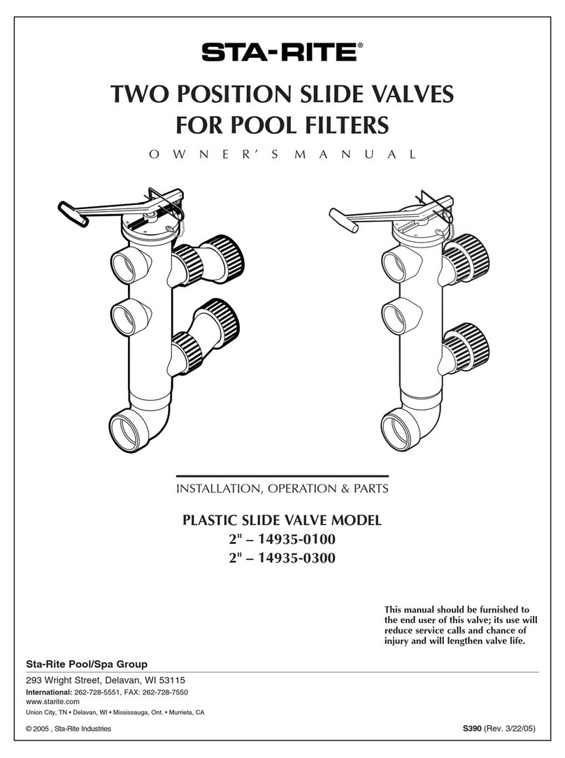
STA-RITE
STA-RITE 14935-0100 owner's manual
Graco
Graco Therm-O-Flow 25C994 instructions

Woodward
Woodward 8440-2250 Technical manual
Tridonic
Tridonic basicDIM Wireless installation instructions
