Tellabs 6008C User manual
6008C
DX-to-E&M Signaling Converter
Subassembly
•-rtellabs
technical manual
76-816008C
rev B
08/87
Please
Note:
The
6008C
subassembly
can be
optionally
installed (by
the
customer
or
the
fac-
tory) on
the
Tellabs
6132
2Wire-to-4Wire
or
4Wire-
to-4Wire
Terminal
Interface
Module
as
well
as on
the
6131 module.
When
installed on a6132,
the
6008C
and
its
host
module
are
referred
to,
and
can be
ordered
as,
the
6132C.
practice section
816008C
©Tellabs, Inc., 2
November
1985
all rights reserved, printed in USA
1.
general
description
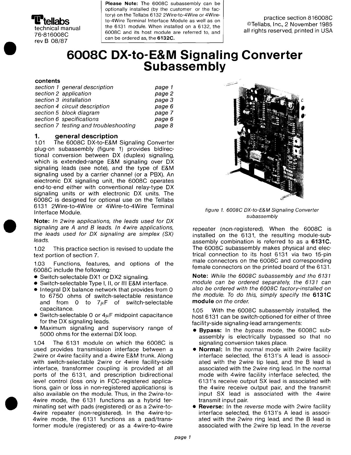
1.01
The
6008C
OX-to-E&M Signaling
Converter
plug-on
subassembly
(figure
1)
provides bidirec-
tional conversion
between
OX
(duplex) signaling,
which is
extended-range
E&M signaling over
OX
signaling leads (see note),
and
the
type
of
E&M
signaling used
by
a
carrier
channel
(or aPBX). An
electronic
OX
signaling unit,
the
6008C
operates
end-to-end
either
with
conventional
relay-type
OX
signaling units
or
with
electronic
OX
units. The
6008C
is
designed
for
optional
use
on
the
Tellabs
6131
2Wire-to-4Wire
or
4Wire-to-4Wire
Terminal
Interface
Module.
Note: In 2wire applications, the leads
used
for
OX
signaling are A
and
Bleads. In
4wire
applications,
the leads used
for
OX
signaling are simplex
(SX)
leads.
1.02 This
practice
section is revised
to
update
the
text
portion
of
section
7.
1.03 Functions, features, and
options
of
the
6008C
include
the
following:
•
Switch-selectable
OX1
or
OX2 signaling.
•Switch-selectable Type
I,
II,
or
III E&M interface.
•Integral
OX
balance
network
that
provides from 0
to
6750
ohms
of
switch-selectable
resistance
and from 0
to
7J.-tF
of
switch-selectable
capacitance.
•Switch-selectable 0
or
4fLF
midpoint
capacitance
for
the
OX
signaling leads.
•Maximum signaling
and
supervisory
range
of
5000
ohms
for
the
external
OX
loop.
1.04 The 6131
module
on
which
the
6008C
is
used provides transmission
interface
between
a
2wire
or
4wire
facility and a
4wire
E&M trunk. Along
with switch-selectable
2wire
or
4wire
facility-side
interface,
transformer
coupling is provided
at
all
ports
of
the
6131, and prescription bidirectional
level control (loss only in FCC-registered applica-
tions, gain
or
loss in non-registered applications) is
also available on
the
module. Thus, in
the
2wire-to-
4wire
mode,
the
6131
functions
as ahybrid ter-
minating
set
with pads (registered)
or
as a
2wire-to-
4wire
repeater
(non-registered). In
the
4wire-to-
4wire
mode,
the
6131
functions
as a
pad/trans-
former
module
(registered) or as a
4wire-to-4wire
•
•
contents
section 1general description
section 2application
section 3installation
section 4
circuit
description
section 5
block
diagram
section 6
specifications
section 7testing
and
troubleshooting
page
1
page
2
page
3
page
6
page
7
page
6
page
8
page
1
figure
1.
6008C
DX-to-E&M
Signaling
Converter
subassembly
repeater
(non-registered). When
the
6008C
is
installed on
the
6131,
the
resulting module-sub-
assembly
combination
is referred
to
as a6131C.
The
6008C
subassembly makes physical and elec-
trical
connection
to
its
host
6131 via
two
15-pin
male
connectors
on
the
6008C
and corresponding
female
connectors
on
the
printed board of
the
6131.
Note: While the
6008C
subassembly
and
the 6131
module
can
be
ordered separately, the 6131 can
also be
ordered
with the
6008C
factory-installed on
the module.
To
do this, simply
specify
the
6131C
module on the order.
1.05 With
the
6008C
subassembly installed, the
host
6131 can
be
switch-optioned
for
either
of
three
facility-side signaling-lead arrangements:
•Bypass:
In
the
bypass mode,
the
6008C
sub-
assembly
is electrically bypassed so
that
no
signaling conversion takes place.
•
Normal:
In
the
normal
mode
with
2wire
facility
interface
selected,
the
6131's Alead is associ-
ated with
the
2wire
tip lead, and the Blead is
associated with
the
2wire
ring lead.
In
the
normal
mode
with
4wire
facility
interface
selected,
the
6131's receive
output
SX lead is associated with
the
4wire
receive
output
pair, and
the
transmit
input
SX lead is associated with
the
4wire
transmit
input
pair.
•Reverse: In
the
reverse mode
with
2wire
facility
interface
selected,
the
6131's Alead is associ-
ated with
the
2wire
ring lead, and
the
Blead is
associated
with
the
2wire
tip
lead. In the reverse

l
, ,
, , E
:>--<:(E
)(
,,
I I
-t-~
i ,
, 1
21
'>--<'
M'
,
, I
II
_ 1 I
- , I
BOOBC
,I
PBX
trunk
circuit
figure
2b. DX2 signaling, TL31E
or
TC31E
-4BV
the
600BC
in
these
two
signaling
modes
is as
follows:
•
In
OX1
operation, the
600BC
accepts
local
(terminal-side) M-Iead inputs and derives
the
appropriate
OX
current
for
transmission to the
distant
(facility-side) location. Also in
OX1
opera-
tion,
the
600BC
derives local E-Iead
output
states
in response
to
OX
current
received from the dis-
tant location.
•
In
OX2 operation, the
600BC
accepts
local E-Iead
inputs
and derives
the
appropriate
OX
current
for
transmission to
the
distant
location. Also
in
OX2
operation, the
600BC
derives local M-Iead
output
states in response
to
OX
current
received from
the
distant
location.
OX
signaling loop limits
2.03 For
proper
OX
signaling operation, total
resistance of
the
OX
signaling loop
between
the
600BC
and
the
OX
unit at
the
distant facility-side
location must
not
exceed
5000
ohms. In 2wire
applications, total
OX
signaling-loop resistance is
simply
the
resistance
of
the
metallic loop
between
the
two
OX
signaling units. In
4wire
applications,
where signaling
takes
place
over
the
SX
leads of
the
transmit
input
and receive
output
pairs, total
OX
signaling loop resistance equals
one
half of the
loop resistance
of
the transmit input pair plus one
half of
the
loop
resistance
of
the receive
output
pair.
E&M
interface
2.04 With
either
OX1
or
OX2 operation selected,
the
600BC
can be switch-optioned
for
Type I
or
Type
II
E&M interface.
In
OX1
operation only, the
600BC
is
compatible
with aType III E&M interface
when
optioned
for
Type
I.
Figures 2through 4
show
the
various E&M
interfaces
available with
OX1
and
OX2
operation. Registered Facility
Interface
Codes
are also provided
where
applicable
(i.e.,
for
all inter-
faces
exceptType
III with
OX1).
-4BV
,,
EI ,
)(
2i
):>--<:
,,
,,
i
i~-4BV
I ,
,,
, I
!
n~:;~L£'~n
~
,>--<'
~M':
: M
,,
I, _
BOOBC
: :
PBX
trunk
cirCUit
figure
2a. DX1 signaling, TL31M
or
TC31M
1
figure
2. Type IE&M
interface
arrangements
practice
section B1600BC
mode with
4wire
facility
interface
selected,
the
6131's receive
output
SX lead is associated with
the
4wire
transmit input pair, and
the
transmit
input SX lead is associated with
the
4wire
receive
output
pair.
1.06
Input
power
is supplied to
the
600BC
sub-
assembly via
the
host 6131 module. Integral voltage
regulators on the
600BC
and
the 6131 allow the
6131C
to
operate
on filtered,
ground-referenced
-42
to
-56Vdc
input. Maximum
current
required by
the
600BC
and its host 6131
together
is 110mA
plus
OX
sending current.
1.07 As
stated
above,
the
600BC
plugs
onto
the
printed circuit board
of
its host 6131, aType 10
module. The resulting 6131C, in turn, plugs into
one
position of aTellabs Type 10
Mounting
Shelf, ver-
sions of
which
are available
for
relay-rack and
apparatus-case installation. In relay-rack applica-
tions,
up
to 12
modules
can be
mounted
across a
19-inch rack,
while
up
to 14 modules
can
be
moun-
ted across a
23-inch
rack.
In
either
case, 6
inches
of
vertical rack
space
is used.
page
2
2.
application
2.01
The
600BC
OX-to-E&M Signaling
Converter
subassembly, when installed on its
host
6131
2Wire/4Wire-to-4Wire
Terminal
Interface
Module,
interfaces a
2wire
or
4wire
facility
that
uses
OX
signaling with a
4wire
E&M
trunk
that
normally
interfaces
a
carrier
channel. When the host 6131
module is
optioned
for
2wire
facility
interface,
signaling is derived via
the
module's
Aand 8leads.
When the 6131 is
optioned
for
4wire
facility
inter-
face, signaling is derived via the module's receive
output
SX and
transmit
input
SX leads.
OX1
/OX2
signaling
2.02 The
600BC
can be
switch-optioned
for
a
OX1
or OX2 signaling arrangement. Operation of

practice
section
816008C
::-t'
~-4BV
~M-LEAD
h
M
!ETECTOR
-=
,
,
,
r
PBX
trunk circuit
,
:>--<
,
,
,---_-;.19~\
,
>--<
J:
SG
7
-c::::
BOOBC
-48V-48V
~
figure 3a.
DX1
signaling,
TL32M
or
TC32M
figure 3b. DX2 signaling, TL32E
or
TC32E
figure 3. Type
1/
E&M
interface
arrangements
figure
4.
DX1
signaling, Type
1/1
E&M
interface
arrangement
2.07 The
amount
of
resistance
required in
the
balance
network
is
simply
the
total resistance of
the
external
OX
signaling
link. This is
because
a1210-
ohm resistive
component
integral
to
the
6008C's
balance
network
automatically
compensates
for
the
resistance
of
the
OX
unit
associated
with
the
ter-
minal
equipment
at
the
opposite
end
of
the
OX
signaling
link. The five
KILOHMS
positions
of
the
6008C's
OX-balance-network
DIP
switch
introduce
from 0
to
6750
ohms
of resistance, in
250-ohm
increments, to
permit
matching
(within
125
ohms)
of
OX-link
resistance
up
to
5000
ohms.
2.08
No
specific
formula
exists
for
calculating
the
amount
of
capacitance
required
to
properly
balance
the
circuit. This
amount
depends
upon a
variety
of
factors.
For
example,
little
capacitive
balance is
required in
most
4wire
OX
circuits
because
the
signaling pairs
are
separated
by
substantial
relative
distances
and
are
therefore
coupled
by
very
little
mutual
capacitance.
Numerous
other
factors,
including
cable
gauge
and splicing format, also
affect
the
OX
signaling
link. The
cumulative
effect
of
these
factors
makes
prediction
of
the
required
amount
of
balancing
capacitance
difficult. Atrial-
and-error
procedure
is
therefore
necessary
to
achieve
proper
capacitive
balance. The
three
[LF
positions
of
the
6008C's
OX-balance-network
DIP
switch
allow
from 0
to
7
[LF
of
capacitance
to
be
introduced
into
the
circuit
in
1[LF
increments.
3.
installation
inspection
3.01 The
6008C
OX-to-E&M
Signaling
Converter
subassembly
should
be visually
inspected
upon
arrival
to
find
possible
damage
incurred
during
ship-
ment. If
damage
is noted, aclaim
should
immedi-
ately
be filed with
the
carrier. If stored,
the
subassembly
should
be visually
inspected
again
prior
to
installation.
page
3
-4BV
>--<~3G
>--<,
MM
>--<;
SB
,
,
,
,
,PBX
trunk
circuit
,
>--<'
,
BOOBC
:
E
q
)(
::
SG
-4BV~
signaling-lead midpoint
capacitance
2.05
To
prevent
unwanted
signaling-state
changes
toward
the
facility-side
termination, a
switch option on
the
6008C
allows
4[LF
of capaci-
tance
to
be placed
across
the
midpoint
of
the
6008C's
OX
signaling leads. This
midpoint
capaci-
tance
must
be provided in all
2wire
applications.
Normally, it is also provided in all
4wire
applications
except
those
involving an
unusually
short
OX
signaling link. In
short-link
applications,
the
mid-
point
capacitor
is
switch-optioned
out
of
the
circuit
for
O[LF
of
midpoint
capacitance,
which
allows
easier
alignment
of
the
6008C's
integral
OX
balance
network
than
would
otherwise
be possible
with a
short
OX
link.
OX
balancing
2.06 Aresistive and capacitive
OX
balance
net-
work
in
the
6008C
is used
to
balance
the
module's
internal
OX
impedance
against
that
of
the
external
OX
signaling link. Proper
OX
balance
ensures
optimum
performance
of
the
6008C's
OX
unit
for
the
specific
length (in ohms)
of
the
OX
signaling
link
and also minimizes pulse distortion.
~
-

figure
5.
6008C
option
and
alignment
switch
locations
section
of
the
6008C's
integral
OX
balance
network
may
not
be
possible.
Paragraphs
3.10
and
3.11
pro-
vide
appropriate
non-prescription
alignment
pro-
cedures
for
the
resistive
and
capacitive
sections
of
the
OX
balance
network.
non-prescription
optioning
3.05 If prescription option-switch
settings
are
not
available
for
the
6008C,
set
its three option
switches
as
directed
below.
Note:
If
the
Registered
Facility
Interface
Code
is
known
for
a
particular
application,
the
6008C's
two
signaling-related
option
switches
(S10
and
S13)
can
be
set
as
indicated
in
table
2.
3.06 DX1
or
DX2
Operation.
Two-position slide
switch
813
selects
either
DX1
or
DX2 operation
for
the
6008C.
Set
813
as follows:
•For
DX1
operation
(receiving M-lead signals from
and
sending
E-Iead signals toward E&M terminal
equipment),
set
813
to
OX1.
•For DX2
operation
(receiving E-lead signals from
and
sending
M-Iead signals toward E&M terminal
equipment),
set
813
to
OX2.
3.07
E&M
Signaling
Interface.
Two-position
slide switch
810
selects
Type
I,
II,
or III E&M inter-
face
for
the
6008C.
Set
810
as follows:
•
To
1/1/1
for
Type IE&M interface.
•
To
/I
for
Type
II
E&M interface.
•
To
1/1/1
for
Type III E&M
interface
(available only
when
813 is
set
to
DX1).
3.08
Signaling-Lead
Midpoint
Capacitance.
The
MPC
position
of
nine-position DIP switch 815
(the
rightmost
switch position) allows
either
4,uF
or
O,uF
of midpoint capacitance
to
be placed across the
6008C's
DX signaling leads. Set
the
MPC
switch
as
follows:
•
In
all
2wire
applications, and in all 4wire appli-
cations
except
those
involving an unusually
short
DX signaling link, set
the
MPC switch to
IN
to
provide
4,uF
of
midpoint
capacitance.
[ E
LED
[ M
LED
81-6008C
513
o~L
P1
[
P2
[
510
~
1I111
practice
section
816008C
mounting
and
connections
3.02 The
6008C
subassembly
makes physical
and electrical
connection
to
its
host
6131
module
via
two
15-pin male connectors, P1 and
P2,
located
on the subassembly's
component
side.
To
install
the
6008C
on the
host
6131,
proceed
as follows:
A.
Remove
the
small plastic filler panel
at
the
upper
righthand
corner
of
the
6131's front panel
by pushing it
outward
from
the
rear
of
the
panel.
B.
Orient
the
6008C
subassembly
so
that
male
connector
P1
on the
6008C
lines up with
female
connector
J1 on
the
6131, male connec-
tor
P2
on
the
6008C
lines
up
with
female
con-
nector
J2
on
the
6131,
and
the
small plastic
panel labeled Cand
containing
the
E
and
M
LED's on
the
6008C
lines
up
with
the
opening
at the
upper
righthand
corner
of
the
6131's
front
panel
adjacent
to
the
6131 model number.
C.
Carefully plug
the
6008C
onto
the
host 6131,
ensuring that all
connector
pins on
the
6008C
fit properly
into
their
receptacles
on
the
6131's
female
connectors
and also
ensuring
that
the
small plastic panel labeled Con
the
6008C
fits
properly
into
the
opening
in
the
6131's
front
panel.
D.
Finally, install
and
tighten
the
screws (supplied)
that
secure
the
6008C's
four
standoff
posts
to
the
6131's printed
circuit
board.
options
and
alignment
3.03 Before
the
6008C
is placed into service,
three option
switches
on
the
subassembly
must
be
set
and
the
subassembly's integral DX balance net-
work
(also switch-controlled) must be aligned. Two
of
the
option
switches
are
two-position
slide
switches,
while
the
third is
one
position
of
anine-
position DlPswitch. The remaining
eight
positions
of
the
DIP switch
control
the
DX balance network.
Figure 5
shows
the
locations
of
these
switches
on
the
subassembly's printed
circuit
board. In
addition
to
the
6008C's
SWitches, several option
and
align-
ment
switches
on
the
host 6131
must
be
set
as
well.
Instructions
for
setting
the
6131's
switches
are
provided in
the
Tellabs 6131 practice,
while
instruc-
tions
for
setting
the
6008C's
switches
are provided
below.
prescription
optioning
and
alignment
3.04 For prescription
optioning
and
alignment
of
the
6008C
(see
notes
below), required switch set-
tings should be
determined
from
circuit
records
prior
to
installation
of
the
6131
C.
These required
settings
should
then
be
noted
in
the
checklist
column
of
table
1
or
on
the
circuit
layout record
(CLR). During installation, the
6008C
can be
quickly
and easily
optioned
without
referring
to
the
detailed
instructions in
the
text. Simply refer
to
the
check-
list
column
of
table 1(or
to
the
CLR)
and
set
all
switches
as indicated.
Note
1: A
similar
table
and
checklist
are
proVided in
the
Tel/abs 6131
practice
for
prescription
optioning
and
alignment
of
the
host
6131 module.
Note
2:
For
reasons
stated
in
paragraph
2.08
of
this
practice,
prescription
alignment
of
the
capacitive
page
4

table
2.
Registered
Facility
Interface
Codes
and
required
signaling
options
table
1.
Summary
and
checklist
of
6008e
option
and
alignment
switches
practice
section
816008C
Total
resistance
added
is
the
sum
of
those
KILOHMS
switches
set
toward
their
respective
values,
i.e.,
toward
.25, .5,
1,
2,
and
3
and
away
from
KILOHMS.
Please
note
that
a
1210-ohm
resistive
component
integral
to
the
resistive
section
auto-
matically
compensates
for
the
internal
resistance
of
the
OX
unit
at
the
terminal-equipment
end
of
the
OX
link. Thus,
the
required
balance-network
resistance
is
simply
the
total
resistance
of
the
OX
signaling
link.
Determine
this
resistance
and
set
the
balance-
network
KILOHMS
switches
as
follows:
•
For
2wire
applications,
the
required
balance-
network
resistance
equals
the
resistance
of
the
2wire
metallic
loop
between
the
6008C
and
the
terminal-end
DX
unit.
Set
toward
their
respective
values
those
KILOHMS
switches
whose
sum
matches
this
amount
as
closely
as
possible.
page
5
Registered Facility
E&M
signaling
OX
signaling 6008C option
Interface Code interface arrangement switch settings*
510 513
TL31
M
or
TC31
M
Type
I
OX1
1/111
OX1
TL31
E
or
TC31
E
Type
I
OX2
1/111
OX2
TL32M
or
TC32M
Type
II
OX1
II
OX1
TL32E
orTC32E
Type
II
OX2
II
OX2
not
applicable
Type
III
OX1
1/111
OX1
*
See
table 1and/or text for information
on
non-signaling-related 6008C options.
switch
option
switch
selection
setting
checklist
OX1
*
or
OX2**
S13
OX1
operation*
OX1
operation
OX2
operation **
OX2
Type
I,
II,
or
III
S10
Type
Iinterface
1/111
E&M
interface
Type
II
interface
II
Type
III
interface
1/111
(available only
with
S13
set
to
DX1)
signaling-lead
S15,
4,uF
IN
midpoint capacitance
(4,uF)
MPC
position OftF
OUT
OX
balance network
S15
(BAL), 250
ohms
toward
.25
resistance
KILOHMS
500
ohms
toward
.5
(0
to
6750 ohms)*** positions 1000
ohms
toward 1
only*** 2000
ohms
toward 2
3000 ohms toward 3
OX
balance network
S15
(BAL),
1,uF
toward 1
capacitance ftF positions
2,uF
toward 2
(0
to
7,uF)***
only***
4,uF
toward 4
*
In
OX1
operation, the 6008C accepts
M-Iead
inputs for
OX
transmission to the remote site
and
derives
E-Iead
outputs
from
OX
signals received
from
the remote site.
**
In
OX2
operation, the 6008C accepts
E-Iead
inputs for
OX
transmission to the remote site
and
derives
M-Iead
outputs
from
OX
signals received
from
the remote site.
***
The
OX
balance network's resistance
and
capacitance switch positions
on
OIP
switch S15
are
cumulative.
Total
resis-
tance
and
capacitance introduced
is
the
sum
of
those
KILOHMS
and
,uF
switch positions set toward their respective
I
values.
•In
4wire
applications
where
the
OX
signaling
link
is
unusually
short,
set
the
MPC
switch
to
OUT
for
no
midpoint
capacitance.
OX
balance
network
alignment
3.09
The
6008C's
integral
resistive
and
capaci-
tive
OX
balance
network
allows
the
subassembly's
internal
OX
impedance
to
be
balanced
against
that
of
the
external
OX
signaling
loop.
Align
the
resistive
and
capacitive
sections
of
the
balance
network
as
directed
below.
3.10
Resistive
Section.
The
five
KILOHMS
switches
on
nine-position
DIP
switch
S15
control
the
resistive
section
of
the
balance
network.
These
switches
introduce
from
0
to
6750
ohms
of
resis-
tance,
in
250-ohm
increments,
to
match
(within
125
ohms)
external
loop
resistance
of
up
to
5000
ohms.
-
~
Table of contents
Popular Media Converter manuals by other brands


H&B
H&B TX-100 Installation and instruction manual

Bolin Technology
Bolin Technology D Series user manual

IFM Electronic
IFM Electronic Efector 400 RN30 Series Device manual

GRASS VALLEY
GRASS VALLEY KUDOSPRO ULC2000 user manual

Linear Technology
Linear Technology DC1523A Demo Manual

Lika
Lika ROTAPULS I28 Series quick start guide

Weidmuller
Weidmuller IE-MC-VL Series Hardware installation guide

Optical Systems Design
Optical Systems Design OSD2139 Series Operator's manual

Tema Telecomunicazioni
Tema Telecomunicazioni AD615/S product manual

KTI Networks
KTI Networks KGC-352 Series installation guide

Gira
Gira 0588 Series operating instructions

Lika
Lika SFA-5000-FD user guide