TELLARINI POMPE EEM Series Operating instructions

GB SIDE CHANNEL SELF-PRIMING PUMP
User and maintenance manual
Machinery series /
EEM, ENM, ENT, ALM, ALT
Partly completed machinery series
EEMQ, ENMQ, ENTQ, ECC, ALMQ, ALTQ, ALCC
T
TT
TE
EE
EL
LL
LL
LL
LA
AA
AR
RR
RI
II
IN
NN
NI
II
I
P
PP
PO
OO
OM
MM
MP
PP
PE
EE
E
s.n.c.

2
Fig. 1
Fig. 2
Fig. 3A Fig. 3B

3
Fig. 5
Fig. 8
Fig. 6
Fig. 4
Fig. 9
Fig. 7

4
Fig. 10 Fig. 11 Fig. 12
Fig. 13 Fig. 14
Fig. 15 Fig. 16 Fig. 17 Fig. 18
Fig. 19 Fig. 20 Fig. 21 Fig. 22
Fig. 23 Fig. 24 Fig. 25 Fig. 26

37
GB USER AND MAINTENANCE MANUAL
Translation of the original instructions
Reproduction, for any purpose, of parts of the text or of the
drawings is prohibited without prior written consent from the
manufacturer.
WARNING concerning machinery
Consult carefully before installing the machinery.
WARNING concerning partly completed machinery
Consult carefully before incorporating the partly completed machinery.
When reading, omit information relative to parts that are not present.
Comply with all applicable general safety criteria, to guarantee safe use of
the machinery in which the partly completed machinery is incorporated.
IMPORTANT
Themachineryandpartlycompletedmachinerydescribed hereinmustonlybe
usedbypersonswithappropriateknowledgeoftheiruse.Theymustnotbeleft
in a place accessible to children or to persons that might use them in an
inappropriate and, consequently, potentially dangerous manner. They must be
used exclusively in compliance with the intended use declared by the
manufacturer and in compliance with the safety specifications indicated in this
manual.Theymustalwaysbesupervisedduringuse.
Chapter 9 and relative subchapters, printed in italics, contain information for
maintenance exclusively for use by qualified technicians and must be
performedusingappropriate personal protectiveequipment.
This manual describes the use of the pump in compliance with the design
specifications and illustrates the technical specifications, methods of
installation, use and maintenance and information concerning residual
risks related to use. The manual must be considered part of the pump and
be kept for future consultation for the entire useful life of the pump.
The manufacturer shall not be held responsible in cases of improper use
of the pump, use contrary to specific national regulations, installation not in
conformity with the declared specifications, faults in the power supply,
unauthorized modifications and operations, use of non-original spare parts
or parts not relative to the specific model, total or partial failure to comply
with the instructions indicated herein.
CONTENTS
1 – DESCRIPTION OF SYMBOLS USED - GLOSSARY ...................37
2 – USE OFTHE MACHINERY/PARTLYCOMPLETED MACHINERY......37
2.1 – Specifications of pumped liquid .............................................37
2.2 – Environment of use .................................................................38
3 – TECHNICAL DESCRIPTION............................................................38
3.1 – Specifications...........................................................................38
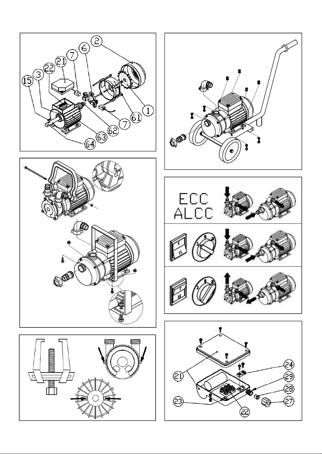
3.2 – List of components ..................................................................38
3.3 – Maximum priming height ........................................................39
3.4 – Pumping direction....................................................................39
3.5 – Shaft sealing devices ..............................................................39
3.6 – Optional accessories available ..............................................39
4 – INSTRUCTIONS FOR INSTALLATION AND USE .......................39
4.1 – Handling....................................................................................39
4.2 – Installation and use..................................................................39
4.2.1 – Preliminary operations............................................39
4.2.2 – Assembling the hoses.............................................40
4.2.3 – Electrical connection – general instructions ...........40
4.2.3.1 – Connection of single-phase and three-phase pumps 40
4.2.3.2 – Connection of direct current pumps................40
4.2.4 – Starting and stopping..............................................41
4.3 – Washing and storage..............................................................41
4.4 – Use of the by-pass (optional device).....................................41
4.5 – Demolition.................................................................................41
5 – INFORMATION ON RESIDUAL RISKS..........................................41
5.1 – Contact with moving parts......................................................41
5.2 – Temperature of accessible surfaces......................................41
5.3 – Risks caused by spattering and leakage of fluids................41
5.4 – Residual risks caused by faulty operation ............................42
6 – TROUBLESHOOTING ......................................................................42
7 – DECLARATIONS ...............................................................................43
8 – WARRANTY........................................................................................43
9 – NOTES FOR THE SERVICE TECHNICIAN (reserved for qualified
technicians) ...............................................................................................43
9.1 – Disassembling the hydraulic part of the pump.....................43
9.2 – Assembling the hydraulic part of the pump ..........................43
9.2.1 – Replacing the lip seal (brass models type 20 and 50)..........43
9.2.2 –Replacing the lipseal (brass models type 25-30-35-40).......44
9.2.3 – Replacing the mechanical seal ....................................... 44
9.3 – Replacing the brushes ........................................................... 44
1–DESCRIPTIONOFSYMBOLSUSED-GLOSSARY
Safety hazard
Danger of electric shock
Danger of damaging the pump
• The series of products EEMQ, ENMQ, ALMQ, ENTQ and ALTQ are
partly completed machinery identical, respectively, to the machinery of
series EEM, ENM, ALM, ENT and ALT, except for the fact that they are
supplied without the switch and cable for connection to the power
supply but provided with an electrical terminal block. In the rest of the
manual, reference will only be made to the series without the suffix –Q.
When switch and cable are mentioned this refers to the completed
machinery, while when terminal block is mentioned this refers to the
corresponding partly completed machinery.
• The term “series ALCC” refers to the pumps AL 12/20, AL 24/20, AL
12/25, AL 24/25, AL 24/40.
• The type of power supply is indicated in the box identified by the word
“Motor” in the pump ratings plate. 1~ means “single-phase alternating
current”, 3~ means “three-phase alternating current” and
means “direct current”.
2 – USE OF THE MACHINERY/PARTLY COMPLETED
MACHINERY
The machinery or partly completed machinery is a self-priming pump of
“side channel” type. It has been designed and manufactured specifically
for transferring and handling liquids, thanks to some important features:
very rapid self-priming capacity, i.e. suction of air contained in the suction
hose to start pumping;
no damage to the pump if the liquid in the suction tank finishes;
possibility of reversing the flow of liquid (for models supplied with
alternating current).
Although it has been designed for professional use, it can also be used in
a domestic environment, providing the user has become acquainted with
its use, by carefully reading the instructions contained in this manual.
2.1 – PROPERTIES OF PUMPED LIQUID
the liquid to be pumped:
- must have no hard suspended particles (sand, gravel, etc.) which can
cause rapid wear of internal parts. If the liquid to be pumped has this risk
factor, install a suitable filter in the suction hose.
- must not be aggressive towards the materials with which it comes
into contact, i.e.:
1) the material forming the pumping body (brass for series EEM, ENM,
ENT, ECC - AISI 316 stainless steel for series AL);
2) the material of which the shaft is manufactured (AISI 316 stainless
steel);
3) the materials of which the gasket and the sealing device are
manufactured (see Chapter 3.5).
4) (only for models with by-pass) acetalic resin.
- must have suitable viscosity: these pumps are not suitable for very
viscous liquids (such as honey). For series ENM, ENT, ALM, ALT pumps,
consider as an indication of maximum viscosity a mineral oil type SAE 30
at a temperature of 40° C; all other series are suitable for liquids with
viscosity similar to water.
- must have a maximum fluid density of: for series ENM, ENT, ALM,
ALT pumps: 1.1 g/cm3; for other series: density similar to water.
- must have a minimum temperature of: -15°C, in any case above the
freezing temperature of the liquid to be pumped.
WARNING
WARNING

38
- must have a maximum temperature of: models without by-pass:
depending on the rubber used to manufacture the gaskets: 90°C (NBR
rubber, which is standard unless otherwise indicated on the pump), 110°C
(EPDM rubber), 130° C Viton rubber; models with by-pass: 90°C.
Examples of use of the series with brass pump body (series EEM,
ENM, ENT, ECC)
Water, sea water, gas oil, oil, soaps; in the European Union pumps with
brass pumping body are generally not considered suitable for use with
food products, such as milk or olive oil (ref. standard UNI EN 13951).
Application in the food sector is subordinate to checking suitability of the
pumps with the provisions of the specific HACCP plan drawn up by the
user.
Examples of use of series with AISI 316 stainless steel pump body,
material suitable for foods and with excellent resistance to corrosion
and abrasion (series AL)
- liquid foods, such as wine, vinegar, olive oil, milk; for these uses
appropriate methods of washing and disinfecting the pump must be
adopted, according to type of liquid (see Chapter 4.3);
- compatible corrosive liquids (such as fungicides or liquid fertilizers)
- the same liquids permitted for brass pumps, in this case ensuring a much
longer useful life.
Use of the pump in environments in which there is danger
of explosion or fire (as defined by the law) is prohibited; in
particular, do not use with petrol, acetone, solvents, etc.
2.2 – ENVIRONMENT OF USE
- Ventilated, clean and dry closed environment.
- Normal or marine atmosphere, ambient temperature between –15 °C
and 40 °C and maximum relative humidity 80%.
- Maximum installation altitude: 1000 meters above sea level.
3 – TECHNICAL DESCRIPTION
3.1 - SPECIFICATIONS
The pump can perform suction of liquid from one port (suction port),
sending it to the other port (discharge port); the essential parameter
characterizing a pump is capacity Q (quantity of liquid transferred in a
given time); the speed of the pumping operation depends on this.
The capacity of a pump is not fixed, but depends on the total manometric
head H required by the installation, which is the sum of two contributions:
1) difference in height (measured vertically) between the level of liquid in
the tank of destination and that of the tank or origin;
2) energy losses caused by liquid flow in pipes, valves, fittings, and other
elements inserted along its path.
Tab. A indicates the capacity (in litres per minute) as a function of total
manometric head (in metres) for the various pump types. The same table
also indicates the value of the maximum head Hmax developed by the
pump (expressed in bar, unit of pressure measurement), which is reached
when the discharge port is closed, and the maximum equivalent A-
weighted sound pressure level (LeqA) obtained at 1 metre from the
surface of the pump operating with water at 20°C.
3.2 – LIST OF COMPONENTS
Tab. B contains the list of all components, and refers to Figs. 1, 2, 3A, 3B,
4, 9.
-Fig. 1: exploded drawing of single-phase electric pumps type ENM 20,
ENM 20 L, ALM 20, ALM 20 L, EEM 20, EEM 20 L and three-phase
electric pumps type ENT 20, ENT 20 L, ALT 20 e ALT 20 L.
-Fig. 2: exploded drawing of single-phase electric pumps type ENM 25,
ENM 25S, ENM 30, ENM 35, ENM 40, ENM 50, ALM 25, ALM 30, ALM
40, ALM 50, EEM 25, EEM 30, EEM 35, EEM 40 and three-phase electric
pumps type ENT 25, ENT 25S, ENT 30, ENT 35, ENT 40, ENT 50, ALT
25, ALT 30, ALT 40, ALT 50;
- Fig. 3A: mechanical seal; Fig. 3B: the various systems adopted for fixing
the rotating part of the seal;
- Fig. 4: components of the motor part of direct current pumps; the pumps
CC 12/20, ECC 24/20, AL 12/20, AL 24/20 have the motor part as shown
in Fig. 3 and the pump part as shown in Fig. 1; the pumps ECC 12/25,
ECC 24/25, ECC 24/40, AL 12/25, AL 24/25, AL 24/40 have the motor
part as shown in Fig. 3 and the pump part as shown in Fig. 2.
- Fig. 9 replaces the parts ref. 18, 19, 20 of Figs. 1 and 2 in the partly
completed machinery of series EEMQ, ENMQ,ALMQ, ENTQ and ALTQ.
TYPE 1 m 5 m 10 m Hmax
(bar)
LeqA
(dB) TYPE 1 m 5 m 10 m Hmax
(bar)
LeqA
(dB)
EEM 20 L, ENM 20 L, ENT 20 L 12 30.6 69 ECC 24/25 55 45 30 2.2 75
EEM 20, ENM 20, ENT 20 28 22 15 2.2 77 ECC 24/40 140 108 70 1.7 80
EEM 25, ENM 25, ENT 25 43 29 91.2 71 ALM 20 L, ALT 20 L 80.4 60
ENM 25S, ENT 25S 88 83 77 4.8 83 ALM 20, ALT 20 32 27 21 1.8 77
EEM 30, EEM 35 86 67 42 1.7 74 ALM 25, ALT 25 43 28 81.0 71
ENM 30, ENT 30 86 69 45 1.7 81 ALM 30, ALT 30 89 80 70 4.0 83
ENM 35, ENT 35 86 69 45 1.7 81 ALM 40, ALT 40 137 112 76 1.6 77
EEM 40 125 97 64 1.5 77 ALM 50, ALT 50 205 176 140 2.6 82
ENM 40, ENT 40 130 100 68 1.7 78 AL 12/20 25 17 71.2 79.7
ENM 50 230 208 170 2.9 91 AL 24/20 25 17 71.3 81.8
ENT 50 230 208 170 2.9 91 AL 12/25 55 36 91.3 75.8
ECC 12/20 25 18 10 1.5 75 AL 24/25 55 38 16 1.5 80.8
ECC 24/20 26 20 13 1.6 76 AL 24/40 157 120 73 1.6 72.1
ECC 12/25 55 42 22 1.8 74
Data obtained with water at 20°C – Tolerances: standard ISO 2548 for Class C mass produced pumps
Tab. A

39
3.3 – MAXIMUM PRIMING HEIGHT
The maximum priming height is the maximum difference in level between
the pump and the level of the liquid to be pumped with which it can
perform suction of air from the suction hose and start pumping.
With water at 20°C this value can reach 6 metres, but it depends on the
quantity of liquid present inside the pump during priming; this quantity
depends on the installation methods of the pump and on the configuration
of the hoses. To achieve maximum priming performances, comply with the
following installation measures:
1) Discharge hose: during priming the liquid contained in the pump is
pushed outwards through the discharge port; therefore, the quantity of
liquid decreases, causing reduced priming; avoid this by positioning the
discharge hose so that liquid that has flowed out returns inside the pump,
for example, by pointing the initial part upwards with a difference in level of
50 cm.
2) Suction hose: the initial part pointing upwards with a difference in level
of 20 cm increases the quantity of liquid that remains inside the pump after
it is stopped.
3.4 – PUMPING DIRECTION
Pumps with alternating current motor are two-way: by reversing the
direction of rotation of the motor the direction of liquid flow is reversed. For
this purpose, machines are equipped with a 3-way switch: 0 = off, 1 = on,
2 = on with liquid flowing in the opposite direction to position 1. The typical
pumping directions in single-phase machinery are described in Fig. 8,
lines 2 and 3. In three-phase machinery the direction depends on the
connection to the power supply.
In direct current partly completed machinery, the pumping direction is fixed
and is unrelated to connection of the power supply cables to the terminal
block. The typical pumping direction is described in Fig. 8, line 1. The
typical pumping directions are not binding, and in some examples could
be inverted.
3.5 – SHAFT SEALING DEVICES
The impeller, i.e. the rotating mechanical part that allows the pump to
operate is activated through a shaft by the external motor; the pump body
has an opening for the shaft to pass through. The “shaft seal” is the device
that prevents liquid from leaking through the space between the shaft and
the opening in the pump body. Two types of seal are adopted:
-ring seal (lip seal) with stainless steel spring; the standard seal used in
brass versions is the NBR rubber lip seal, unless otherwise specified by a
label affixed to the pump;
-mechanical seal (Fig. 3A); the standard type of seal used in the
stainless steel series AL is the ceramic/graphite/ AISI 316/ NBR rubber
version, unless otherwise specified by a label affixed to the pump; it greatly
increases the number of hours for which the pump can operate before
requiring maintenance operations and does not cause wear on the shaft.
Various types of seals are available on request (Viton lip seal, silicon
carbide mechanical seals and/or parts in EPDM rubber, Viton, Teflon) to
adapt to the majority of requirements linked to temperature, corrosion and
abrasion. Should you require assistance, please contact our technical
department.
3.6 – OPTIONAL ACCESSORIES AVAILABLE
Handle and truck for easy transport.
Manual by-pass to adjust capacity and head; the relative instructions for
use are included in this manual.
Discharge plug or cock, to drain part of the pump body without removing
the hoses.
Filters, to prevent foreign bodies from entering.
Hose kit.
Hose fittings in nylon or stainless steel (for series AL pumps).
4 – INSTRUCTIONS FOR INSTALLATION AND USE
4.1 – HANDLING
Check the weight of the pump indicated on the ratings plate and adopt
methods in accordance with national safety regulations relative to manual
handling of loads. If necessary use lifting systems, lift trucks, personal
protection equipment for manual handling of loads and to prevent the
danger of crushed limbs. If the pump is to be moved frequently,
accessories (handle and truck) are available to facilitate handling.
Do not lift or transport the pump using the power cable, the hoses or
projecting parts (i.e. the inverter or terminal box). Lift the pump by
firmly holding the metal part.
4.2 – INSTALLATION AND USE
To install machinery supplied completed, strictly follow the
procedures indicated below. To incorporate partly completed
machinery, consider the following instructions within the limits of
their applicability. Use them to draw up instructions for use of the
final machinery. All mechanical and electrical installations to be
performed on unprotected parts must be carried out exclusively by
qualified technical personnel adopting personal protective
equipment to protect hands and limbs against crushing, to protect
from sprays and splashes of liquid and to protect against electrical
shock. These must be selected in relation to specific risk
assessment for the installation to be carried out.
Do not start the pump before having completed the installation.
4.2.1 – PRELIMINARY OPERATIONS
- Remove the pump from the packaging and check that all parts are intact:
any breakages that occur during transport can cause dangers of
mechanical or electrical nature.
- Assemble the handle (Fig. 5) or the truck (Fig. 6), if provided. During
transport, the pump must be disconnected from the power supply. After
transport, the truck must be positioned on a completely horizontal surface.
Check that accidental movements of the truck cannot cause danger.
- Position the pump in a dry place (the pump is not submersible) on a
horizontal surface; leave an empty space of at least 10 cm in front of the
WARNING
WARNING
1Motor fan 14 Seal washer 28 Conical gasket
2Fan cover 15 Tab 29 Threaded sleeve
3Front bearing 18 Capacitor (single-phase pumps
only)
30 Hex head screw
4Pump flange 31 Hex head hollow screw
5Counterflange 19A Toggle switch
(series EEM only)
61 Rear guard
6Brush holder 62 Rear bearing
7Brush 19B Rotary switch (other single-phase
and three-phase series)
63 Casing with stator
8Counterflange gasket 64 Shaft with rotor
9A Stainless steel Seeger ring 20 Inverter box 65 Rear internal part
9B Stainless steel seal ring 21 Terminal box 66 Front internal part
9C Brass seal ring 22 Terminal block 67 Seal
9D Seal spacer 23 Stud 67A Mech. seal rotating part
10 Pump body 24 Cable clamping bracket 67B Mech. seal fixed part - counter-
face
11 Pump cover 25 Straight fitting
12 O-ring 26 Curved fitting 67C Mech. seal fixed part - shroud
13 Impeller 27 Ring nut 68 Motor seal
Tab .B

40
motor cooling fan; secure the feet with bolts to prevent movement or falling
caused by vibrations during operation, to prevent people from tripping over
hoses or the power cable. Make the connections without damaging the
pump.
Never hang or fix the pump using the power cable.
- Fill the pump body with liquid to be pumped through one of the ports,
preventing the liquid from leaking out either through this port or the other
port; as the pump is self-priming, this operation is only necessary the first
time, or if the pump has been emptied; in fact, when it stops sufficient
liquid remains inside for subsequent priming.
Traces of lubricant (cutting fluids, greases) may be present on the inner
walls of the pumping body. If these substances can pollute the liquid to be
pumped (i.e. food substances), initial pumping must be performed
following the cleansing procedure described in Chapter 4.3.
Do not operate the pump dry.
4.2.2 – ASSEMBLING THE HOSES
- As shown in Fig. 5 or Fig. 6, screw the hose fittings to the ports; these
are provided standard with brass pumps, on request (in nylon or stainless
steel) for series AL pumps, after checking that the gaskets are present in
the fittings; the assembly shown is only indicative, the two fittings, straight
and curved, can be inverted.
- Provide a pair of hoses of suitable length and with the same internal
diameter as the external diameter of the fittings. The hose must be flexible
spiral, made of a material suitable for the type and temperature of the
liquid to be pumped, resistant to the internal vacuum and with a higher
operating pressure than the pressure generated by the pump (equal to
Hmax in Table A).
Insert the ends of the hoses into the hose fittings; secure the connection
using a hose clamp. It is not necessary to install a check valve; if the
liquid can contain hard suspended particles install a suitable filter in the
suction hose to retain them; the hose must not exert excessive forces on
the pump. Avoid excessive bending of the hoses to avoid kinks.
Insert the free end of the suction hose into the receptacle from which liquid
is to be drawn, at a depth at least twice the diameter of the hose and at the
same minimum distance from the bottom. Insert the free end of the
discharge hose into the receptacle to receive the liquid.
The discharge hose must be fixed, without compressing it,
to prevent extraction from the collection receptacle during
start-up or operation, which would wet and contaminate the
surrounding environment. In the event of use with dangerous
liquids, wear personal protective equipment selected according to
the specifications of the liquid, to prevent danger of contamination
or contact with exposed body parts.
4.2.3– ELECTRICALCONNECTION –GENERALINSTRUCTIONS
The inverter box (ref. 20) and the terminal box (ref. 21)
contain electrical parts; they must be disassembled
exclusively by a qualified technician, in compliance with
safety regulations.
Before making the electrical connections, check cables, plugs and sockets
for damage. Electrical connections must be protected against dampness
and sprays of liquid. Only use cables and components in conformity with
the safety provisions of Directive 2006/95/EC and suitable for the
current absorbed by the motor.
Pumps with three-phase and direct current motors are not provided with
overload protection; pumps with single-phase motors are provided with an
internal overload protection device and automatic reset only if the words
“Protetta da sovraccarico - Overload protected” appear on the yellow label
affixedtothepump.
4.2.3.1–CONNECTIONOFSINGLE-PHASEANDTHREE-PHASEPUMPS
Required specifications of the power supply
network
• voltage and frequency coinciding with those indicated on the pump
ratings plate (tolerances: 10% on voltage and 2% on frequency);
• provided with an efficient earthing system and equipped with a high
sensitivity differential switch (30 mA) installed in line;
• protected against overcurrents
• (if the pump is not already equipped with this) equipped with overload
protection system calibrated to the current (A) indicated on the pump
ratings plate;
• (for models with cable without plug and models with terminal block)
equipped with a power isolation device.
Models with switch, cable and plug
• select a power socket compatible with the plug, equipped with earthing
device, away from possible sprays of liquid and in an accessible
position.
• Make sure the switch is positioned to off (0).
• Arrange the cable so that it cannot be knocked or tripped over.
• Insert the plug into the power socket.
• If an extension cable is required, it must be selected according to the
current regulations and the data indicated on the pump ratings plate; the
electrical connection must be protected against possible sprays of liquid.
Models with switch and cable, without plug
Connection to the power supply network must be performed
exclusively by qualified technicians, in compliance with the
regulations regarding electrical installations and with all the safety
rules applicable to the type of operation.
The power supply must be disconnected before making the
connection. First connect the earth conductor, followed by the line
conductors.
Models with terminal block
Connection to the power supply network must be performed exclusively
by qualified technicians, in compliance with the regulations
regarding electrical installations and with all the safety rules
applicable to the type of operation. The power supply must be
disconnected before making the connection. The power cable
must be provided with earth conductor. Connection of the cable to the
partly completed machinery is described below with reference to Fig.
9.
• Remove the cover of the terminal box (ref. 21) after having
unscrewed the fixing screws.
• Insert the power cable through the ring nut (ref. 27), the conical
gasket (ref. 28), the threaded sleeve (ref. 29) of the terminal box
and clamp the ring nut.
• Connect the earth conductor to the motor casing at the stud ref. 23
identified by the symbol , using the bolts provided.
• Connect the power conductors to the terminal block (ref. 22)
following the instructions indicated in the label inside the cover of
the terminal box.
• Use the cable clamping bracket ref. 24 to fix the power cable, the
right way up or overturned depending on the diameter of the cable;
check that it is secured effectively against pulling and twisting of
the cable.
• Replace the cover of the terminal box and fasten it using the
screws removed previously.
4.2.3.2– CONNECTION OF DIRECT CURRENT PUMPS
Required specifications of the power supply network
• voltage coinciding with that indicated on the ratings plate of the partly
completed machinery (tolerances +5% - 10%);
• protected against overcurrents;
• equipped with overload protection system;
• equipped with a power isolation device.
• the partly completed machinery is designed to be supplied by a
battery; if another type of generator is used, assess the risk of
dangerous voltages being present on accessible metal parts of the
partly completed machinery; in particular, bear in mind that the
negative pole of the terminal block supplying the partly completed
machinery is connected to the casing of its motor.
Connection instructions
• Remove the terminal box (ref. 21), after having unscrewed its fixing
screws.
• Insert the power cable through the cable grommet.
• Connect it to the terminal block complying with the polarity (+, -)
indicated.
• If it is necessary to secure the cable against pulling or twisting, take
WARNING
WARNING

41
the necessary measures.
• Replace the terminal box and fasten it using the screws removed
previously.
4.2.4 – STARTING AND STOPPING
• Do not start the pump before having completed installation.
• Do not start the pump with wet hands or while standing on wet
surfaces.
• Under no circumstances insert fingers or other body parts or
objects through the ports: the pump contains moving parts.
Check that the hoses are positioned correctly. If the pump was supplied with a switch,
start it by switching this to the on position corresponding to the direction of pumping
required. If the pump was supplied with the terminal block, start it byconnecting it to
thepower supply.
In this phase, take great care that there are no leaks or
sprays of liquid from the installation. It these are present,
stop thepumpimmediatelyandtakeaction toeliminatethem.
The pump must not run with the hoses completely closed for
more than one minute.
After a short period required for priming, the pump will start to transfer
liquid.
If pumping is not obtained and the suction hose bubbles air into the liquid
to be sucked up this means that the pump is pumping in the opposite
direction: in this case stop the pump and reverse the pumping direction or
stop the pump and invert connection of the hoses to the ports.
Operation must always be supervised;
check that the following do not occur:
overheating of the motor surface, reduction
in speed or stopping, abnormal noises or other events that indicate
malfunctioning. In this case, stop the pump immediately, remove the
plug (where present) from the socket and consult Chapter 6.
The noise produced by brass pumps type 20, 25, 30, 35, 40 if they are run
when dry (to be avoided at all costs) does not indicate a fault, but is
caused by the fact that in these models the impeller slides on the shaft to
facilitate maintenance.
To stop the pump, position the switch to stop (0) or disconnect the power
supply.
After it is switched off, the pump remains filled with
liquid, which is essential for priming; if there is any
chance of the ambient temperature dropping to
below the freezing point of the liquid, empty the pump body to avoid
breakage.
4.3 – WASHING AND STORAGE
Before removing the hoses discharge any pressure present
inside the pump. If accessible surfaces are hot (see Chapter
5.2) wait for the pump to cool before handling it or use
appropriate gloves.
If the pump is used for dangerous substances, the user is
responsible for defining the procedures for handling, washing,
storing and disposal of waste fluids in compliance with the safety
regulations in force for the specific substances treated.
If the pumped liquid has no particular problems, (i.e. water, sea water or
soap), in the event of an extended period of disuse, wash the inner walls
of the pump by pumping clean water, empty completely, dry the outer
surfaces with a soft cloth, coil the electric cable and hoses and store in a
dry and protected area.
Cleansing procedure
This allows deeper cleaning than the procedure described previously and
can be used in many cases. In uses with foods it is performed during
installation and as part of the wash cycle.
• Prepare a detersive solution in a receptacle (i.e. common dishwashing
liquid diluted with clean hot water at 40-50°C).
• Insert the suction and discharge hoses of the pump into the receptacle
and recirculate the liquid for 5 minutes.
• Pump clean water until complete rinsing is obtained.
Use with slightly perishable food substances (vegetable oil, wine,
vinegar)
• Before and after use:
• Carry out the cleansing procedure;
• use the pump to recirculate a suitable sanitizing and disinfecting solution
(i.e. based on peracetic acid) for an adequate time;
• rinse the inside of the pump body by pumping clean water until the
sanitizing and disinfecting solution has been completely eliminated.
Before use, perform the start-up procedure, discarding a first fraction
of liquid. Dispose with the fluid used for washing and the discarded
liquid from start-up in compliance with the current provisions of law.
In the specific case of use with vegetable oils, if the pump is to remain
in disuse for a short period of time and subsequently used again for
the same type of oil, it can simply be emptied and the ports capped.
Use with highly perishable food substances (such as milk)
Wash before use, at each time interval established by the HACCP
protocol applied and after use, disassembling the pump, cleansing and
disinfecting its parts with methods depending on the type of liquid. This
operation must be carried out by qualified personnel experienced in
performing the pump disassembly and reassembly procedures.
4.4 – USE OF THE BY-PASS (optional device)
The by-pass is a device to adjust capacity and head of the pump and is
located on the outside in the form of a knob; it can be rotated counter-
clockwise to reduce the maximum capacity to around half and the
maximum head by around a quarter. During the priming stage close the by
-pass by rotating the knob completely clockwise, as priming capacity is
greatly reduced with the by-pass open.
4.5 - DEMOLITION
At the end of its useful life the pump must be demolished, in strict
compliance with the standards in force in the country of use. Do not
neglect any residue of liquid present inside the pump body.
Only EU countries
The pump belongs to the category of electric and electronic
equipment (EEE). The symbol shown here means that it cannot be
disposed of as domestic waste. At the end of its useful life the
owner must deliver the pump to a WEEE collection point, where it
will be subjected to recycling. For more information, contact the
relevant local authority department or the store from which the pump was
purchased.
5 – INFORMATION ON RESIDUAL RISKS
5.1 – CONTACT WITH MOVING PARTS
Do not insert objects through the holes in the fan cover (ref. 2), which
covers the motor cooling fan.
5.2 – TEMPERATURE OF ACCESSIBLE SURFACES
In typical conditions of use, the outer surfaces of the motor part
can reach temperatures in excess of around 40°C higher than the
surrounding ambient temperature. The outer surfaces of the
pumping body reach the temperature of the pumped liquid, and
can therefore be very hot or very cold. In the event of these temperatures
representing a danger, the user must adopt suitable protective measures
(enclose the pump with barriers, handle using suitable gloves).
5.3 –RISKSCAUSEDBYSPATTERINGANDLEAKAGEOFFLUIDS
Undesirable leakage or spraying of liquid may occur, for example,
in the following cases:
- installation procedure carried out incorrectly;
- wear and tear of hoses;
- wear and tear of sealing device (resulting in spattering of liquid from the
space between the flange and the pump body) or of other gaskets (O-ring
or counterflange gasket);
- corrosion of the pump body;
- incorrect reassembly after maintenance;
- pumping of cold liquids, with water vapour condensation forming on the
outer surface of the pumping body and consequent dripping.
These events cause a wet environment (with danger of electric shock,
danger of slipping, etc.) and the risk of persons, animals or objects being
struck by jets of liquid. In particular, maximum caution must be taken when
pumping liquids that are flammable, corrosive, at high temperature or in
WARNING
WARNING

42
any way dangerous for living things or for the environment. The user must
assess these risks and if necessary provide appropriate protection from
jets of liquid (i.e. screens) and collection vessels in a suitable position.
Liquid from leakages must be removed and disposed of correctly and
safely.
5.4 – RESIDUAL RISKS CAUSED BY FAULTY OPERATION
The pump is not provided with audible or visual alarms to indicate
breakages or malfunctioning. Therefore, the user must take suitable
measures to avoid damages (i.e. flooding) caused by failure or faulty
operation of the pump (i.e. installation of alarms, back-up pumps, etc.).
Problem Possible cause Remedy
Motor not turning and no humming
sound
No electricity Check the power supply
System overcurrent or overload protection
triggered Reset the protective device; if the problem persists contact
a qualified technician
Plug not inserted Insert the plug
Power connections interrupted or incor-
rect electric connection Contact a qualified technician
Switch positioned to “off” Switch to the correct “on” position
Internal overload protection triggered (only
for pumps provided with this)
The protection is reactivated automatically; if the protection
is triggered again this means the application is too heavy
for the pump
Electrical fault Contact a qualified technician
Motor making humming sound but not
turning Impeller blocked Contact a qualified technician
Electrical fault Contact a qualified technician
Motor turning at low speed and
pump has reduced capacity Incorrect supply voltage Supply the pump with the voltage indicated on the
ratings plate
Overload Application too heavy for the pump
Motor turning but reduced or no liquid
capacity
Suction hose end incorrectly positioned See Chapter 4.2.2
Infiltration of air or leakage of liquid Check hoses, tightness of hose clamp, fitting gaskets
Hoses or filters (if provided) clogged Clean hoses and filter
Pump clogged Contact a qualified technician
Pump worn Contact a qualified technician
Operating head too high Check the head
Pump not priming
Excessive suction height Check the suction height
Pump not filled with liquid Fill the pump with liquid
Suction hose end incorrectly positioned See Chapter 4.2.2
Pump incorrectly positioned See Chapter 4.2.1
Infiltrations of air Check hoses, tightness of hose clamp, fitting gaskets
Wear and tear on gaskets or seal Contact a qualified technician
Pump worn Contact a qualified technician
Pump bubbling air in the suction tank Incorrect pumping direction Reverse pumping direction
Motor overheating
Overload Application too heavy for the pump
Excessive liquid temperature Application too heavy for the pump
Electrical fault Contact a qualified technician
Abnormal noise during pumping
Foreign bodies have entered the pump Contact a qualified technician
Impeller broken Contact a qualified technician
Impeller seized Contact a qualified technician
Bearing worn Contact a qualified technician
Pump leaking Wear and tear on gaskets or seal Contact a qualified technician
6 - TROUBLESHOOTING

43
7 – DECLARATIONS
The certification below is based on the declarations drawn up by the
manufacturer in accordance with Directive 2006/42/EC of reference for the
machinery and partly completed machinery described in this manual. A
copy of this declaration is available from the manufacturer and is supplied
on request or always in the event of supplying complex installations. The
certification below summarises the principles of conformity indicating the
essential elements established by this Directive.
The company TELLARINI POMPE s.n.c di G. Tellarini & C. with
headquarters in via Majorana, 4 - Lugo (RA) – Italy, declares under its sole
responsibility that:
(Declaration of Conformity) the side channel self-priming pumps series
EEM, series ENM, series ENT, series ALM, series ALT to which this
certification refers comply with the essential safety requirements
established by:
- Machinery Directive 2006/42/EC and national implementation provisions
- Electromagnetic Compatibility Directive 2014/30/UE and national
implementation provisions
- Low Voltage Directive 2014/35/UE and national implementation
provisions
and are in conformity with:
- Directive 2011/65/EU on the restriction of the use of certain hazardous
substances in electrical and electronic equipment and national provisions
for its implementation.
(Declaration of Incorporation) the partly completed machinery relating
to side channel self-priming pumps series EEMQ, series ENMQ, series
ENTQ, series ECC, series ALMQ, series ALTQ, series ALCC, to which
this certification refers, complies with the essential safety requirements
established by:
- Machinery Directive 2006/42/EC and national implementation provisions
- Electromagnetic Compatibility Directive 2014/30/UE and national
implementation provisions
- (with reference to the partly completed machinery included in the field of
application) Low Voltage Directive 2014/35/UE and national
implementation provisions, excluding the requirements associated with
connections to be made to connect the terminal block to the power supply
source
and are in conformity with:
- Directive 2011/65/EU on the restriction of the use of certain hazardous
substances in electrical and electronic equipment and national provisions
for its implementation.
It declares that commissioning of the partly completed machinery must not
take place until the final machinery in which it is to be incorporated has
been declared to be in conformity (if necessary) with the provisions of
Directive 2006/42/EC.
LUGO, 11/02/2019 The legal representative
and technical file holder
Giovanni Tellarini
8 – WARRANTY
The pump is covered by warranty for a period of two years from the
date of purchase by the final user. In the absence of documentation
proving the date, the warranty period starts from July 1st of the year
of manufacture, indicated on the ratings plate. The warranty expires
in any case after 3 years from July 1st of the year of manufacture.
The warranty covers all manufacturing and material defects confirmed
by the manufacturer and consists in the repair or free replacement of
the pump by the manufacturer. Any repairs performed under warranty
do not modify the expiry date of this warranty.
The warranty does not cover damages caused by improper use, by
faulty electrical supply, by use that is not in conformity with the
instructions contained in the “user and maintenance manual”.
Moreover, it does not cover any damages caused or tampering
performed by the user, maintenance operations performed incorrectly
(also with the use of non-original spare parts) and wear related to
normal use (in particular, seals, bearings, capacitors, brushes).
9 – NOTES FOR THE SERVICE TECHNICIAN
Chapter 9 and the relative subchapters contain information for
maintenance to be used exclusively by qualified technicians.
9.1 – DISASSEMBLING THE HYDRAULIC PART
Before disassembly and assembly operations, disconnect
the equipment from the power supply to prevent accidental
starting with moving parts exposed.
Internal parts can have sharp edges; therefore, they should be
handled with care wearing appropriate personal protective
equipment.
Before disassembly discharge any pressure present inside the
pump, wait for it to cool, empty it and dispose of the liquid contained
appropriately; if the pump is used for dangerous substances comply
with the safety regulations in force for handling of these substances.
The references below can be found in Figs. 1, 2, 3A, 3B, 4 and 9
according to the indications provided in paragraph 3.2.
- Unscrew the screws (ref. 30 or ref. 31) of the cover (ref. 11).
- Remove the cover.
- Remove the O-ring (ref. 12).
- Extract the impeller (ref. 13) as follows:
brass models type 20-25-30-35-40: the impeller slides on the shaft (ref.
64), it can be extracted simply using your fingers;
brass models type 50 and all stainless steel models: the impeller is
forced onto the shaft; to remove it use an extractor with appropriately
shaped claws (fig. 7); the hub of the impeller is provided with two
projections for this purpose (fig. 7); for stainless steel models type 20 use
the two projections present on the side of the pump body (fig. 7) for
extraction.
- Remove the tab (ref. 15).
- Extract the pump body (ref. 10) from the shaft.
- (Only for brass models type 20) extract the counterflange (ref. 5) from
the pump body and remove the gasket (ref. 8).
9.2 – ASSEMBLING THE HYDRAULIC PART
(For brass models type 20, first insert the counterflange ref. 5 and position
the gasket ref. 8);
- Insert the tab (ref. 15) in its seat
- Insert the pump body (ref. 10) along the shaft (ref. 64)
- Position the O-ring (ref. 12) in its seat on the pump body
Models with sliding impeller
- Insert the impeller (ref. 13) over the shaft using your fingers.
- Fit the cover (ref. 11) and insert the screws (ref. 30 or ref. 31), gradually
and alternately tightening opposite screws.
Models with forced impeller
The impeller is inserted using a hollow bar with internal diameter slightly
larger than that of the shaft.
- To prevent damaging the bearings, first remove the fan cover (ref. 2) and
place the back of the shaft (the end on which the motor fan ref. 1 is
mounted) on a soft metal surface.
- Striking the impeller (ref. 13) in a central position using the hollow bar and
a hammer, move it towards the wearing surface, leaving 0.1 mm
clearance.
- Fit the cover (ref. 11) and insert the screws (ref. 30 or ref. 31), gradually
and alternately tightening opposite screws.
- Strike the back of the shaft with a punch and hammer.
- Check that the impeller rotates freely rotating the motor fan (ref. 1) and fit
the fan cover (ref. 2).
9.2.1 – REPLACING THE LIP SEAL
(brass models type 20 and 50)
- Remove the worn lip seal (ref. 67) from its seat (located in the
counterflange ref. 5 for models type 20 and in the pump body for models
type 50) striking it using a solid drift of suitable dimensions as shown in
Fig. 23. (type 20) or Fig. 25 (type 50).
-Take an identical new lip seal and place it against the mouth of its seat as
shown in Fig. 24 (type 20) or Fig. 26 (type 50) facing in the correct
direction (the spring must be facing the inside of the pump).
- Insert the lip seal in its seat striking it using a solid drift with a slightly
smaller diameter to that of the outer diameter of the lip seal until it has

44
been completely inserted.
9.2.2 - REPLACING THE LIP SEAL
(brass models type 25-30-35-40)
The pump body is produced in two pieces: pump body (ref. 10) and rear
internal part (ref. 65), which is inserted into the pump body (Fig. 2 shows
the two parts disassembled, Fig. 10 after assembly). To replace the lip
seal (ref. 67) the rear internal part must be extracted from the pump body.
- Place the edge of the pump body on two surfaces made of soft material
(i.e. wood or aluminium) or any other material, provided that two pieces of
paper are placed between surface and body (Fig. 11).
- Take a solid drift (with diameter 28-29 mm and length greater than 60
mm) and strike the lip seal until it is extracted from its seat (Fig. 12).
- Place the lip seal against the edge of the rear internal part as shown in
Fig. 13 and strike it again with the solid drift and hammer; the internal part
will be removed together with the lip seal (Fig. 14).
- Place the pump body on a surface (Fig. 15); take an identical new lip seal
and place it against the mouth of its seat, facing in the correct direction
(the spring must be facing the inside of the pump).
- Insert the lip seal in its seat by striking it using a solid drift with a slightly
smaller diameter to that of the outer diameter of the lip seal until it has
been completely inserted (Figs. 16 and 17).
-Place the rear internal part against the body (Figs. 18 and 20) facing in
the correct direction (Fig. 19).
- Insert the internal part into the body using a solid drift of appropriate
dimensions (Figs. 21 and 22).
9.2.3 – REPLACING THE MECHANICAL SEAL
- Carry out the disassembly procedure without extracting the pump body;
for models type 20 also remove the body (ref. 10), extracting it from the
counterflange (ref. 5)
- Remove the fixing system of the rotating part of the mechanical seal (this
can belong to one of the types in Fig. 3B).
- Extract the rotating part of the seal (ref. 67A), the counterface (ref. 67B)
and the shroud (ref. 67C).
- Take an identical seal, separate shroud and counterface, clean the
lapped races of the rotating part and of the counterface with a soft cloth;
degrease the housing in the pump body and in the shaft, lubricate rubber
parts with soap and water.
-Insert the shroud into the seat in the pump body, followed by the
counterface.
- Insert the rotating part of the seal taking care that its rubber parts are not
damaged when passing over sharp parts.
- Remount the fixing system of the rotating part of the seal; for systems
provided with screws, clamp these so that the length of the rotating part is
between 13 and 14 mm.
9.3 – REPLACING THE BRUSHES
The two brushes (ref. 7) provided in direct current pumps are sliding
contacts subject to wear and must be replaced periodically; a brush is
completely worn when the brush spring is bottomed out; when the brushes
are worn operation first become irregular and then the pump stops; to
replace:
- remove the fan cover (ref. 2)
- unscrew the 2 screws on the brush holder (ref. 6) that connect the wires
of the 2 brushes to the motor winding;
- lift the springs that hold the brushes in place, extract them, replace them
and connect the wires using the 2 screws;
- remount the fan cover.

61
NOTE
Other manuals for EEM Series
1
This manual suits for next models
26
Table of contents
Other TELLARINI POMPE Water Pump manuals
Popular Water Pump manuals by other brands

Little Giant
Little Giant APCP-1700 owner's manual

Ace
Ace ACE5S 1/2 HP installation manual

pumpa
pumpa BLUE LINE PSP Series Translation of the original instruction manual

Sealey
Sealey TP6801 instructions

salmson
salmson MULTI-V 1 Installation and starting instructions

EINHELL
EINHELL BG-PW 48 operating instructions

Varian
Varian HS-16 instruction manual

Sumak
Sumak SMH120 user guide

ETATRON D.S.
ETATRON D.S. eOne MA Operating instructions and maintenance

Stuart Turner
Stuart Turner MAINSBOOST VariQ Installation, operation & maintenance instructions

IMER
IMER PRESTIGE Operating, maintenance, spare parts manual

Rapid
Rapid OP 90 D 35/1 manual