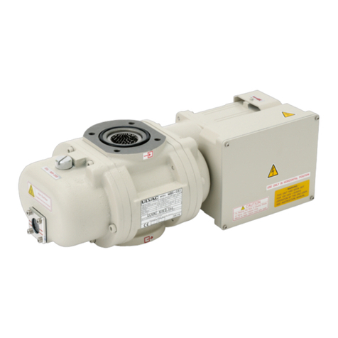
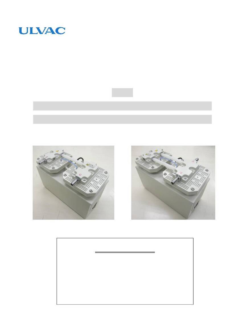
Ulvac ULK-04A User manual

SK00-4802-DI-002-04
No.16.10.20
Instructions Manual
Oil Diffusion Pump
MODEL
ULK-04A
ULK-06A
ULK-10A
ULK-14A
ULVAC, INC.
Components Division
http://www.ulvac.co.jp/
Be sure to read the manual before using this product.
In addition, keep it in a safe and readily available
place.

SK00-4802-DI-002-04
No.16.10.20
i
0. Before Use
We are sincerely appreciate your decision to purchase our product.
Upon receipt of the product, please confirm the contents included are the same as you ordered and
check the product for any damage attributed to transportation etc. just in case.
This manual describes appropriate ways to handle and maintain the product for the safe use and
effective performance. Before using the product, read this instructions manual for the correct use of
the pump.
Install and operate this product according to the local and national safety laws and regulations (such
as fire laws and electric wiring code). Accordingly, you are required to take classes for general safety
that are valid in the country and the local area at the site. No one who hasn't take the classes can
handle the product. The operator is required to have taken such trainings. In addition, the operator
has expertise, skills, qualifications in electrics, mechanics, cargo handling, vacuum, etc.
This product is designed to follow the current regulations as of the preparation of this manual. If the
criteria of the regulations are changed in the future, the compliance is not guaranteed.
If the device with this product built-in doesn't follow the same regulations, or if any changes are
made to the product itself, it may not be guaranteed to have its performance and safety. We don't
guarantee (have no responsibility for) such performance and safety. Any product modifications you
have done are not covered by our warranty and we are not responsible for them.
Before installing/removing this product, keep the product from all the energy sources (such as
electricity, cooling water).
All the parts of this product are not intended for permanent use with the performance at the delivery.
Even under the conditions of use expected in light of common sense, the performance inevitably
deteriorates with time, which tends to cause trouble on the product. We would like to ask you to
grasp your conditions of use and cooperate to provide preventive maintenance to avoid any trouble.
If you cooperate to make preventive maintenance measures, the likelihood of the trouble on this
product attributed to malfunctions caused by worn parts will decrease and that of the risk, such as
downtime, fire, and influence on other processes, attributed to the trouble on this product will also
decrease.
In addition, from the viewpoint of preventive maintenance, you are asked to prepare a maintenance
and inspection plan and conduct parts replacement and overhaul accordingly.
If you have any unclear points, please contact the closest sales office, agency, or our Components
Division.
SK00-4802-DI-002-04
No.16.10.20
ii
0.1 Safety symbol mark
This instructions manual and the product warning labels indicate safety symbol marks for the
understanding of compliance rules. The signs for the symbols are classified as follows.
0.2 Definition of safety symbol mark
This indicates an imminently hazardous situation which, if the product
is misused, will result in operator's death or serious injury.
This indicates a potentially hazardous situation which, if the product is
misused, could result in operator's death or serious injury.
This indicates a potentially hazardous situation which, if the product is
misused, may result in operator's moderate injury or serious damage to
the machinery. This indicates a potentially hazardous situation which
could result in damage to the machinery or malfunctions.
IMPORTANT
"IMPORTANT" is indicated if there is information or content which
needs to be known especially for operation and maintenance work of
this system.
Work that needs training on electrical safety due to the risk of an
electric shock.
Work that is done after checking that the pump temperature decreases
because that part is high in temperature immediately after the pump
stops.
CAUTION
WARNING
DANGER

SK00-4802-DI-002-04
No.16.10.20
iii
0.3 Safety precautions
This section describes a way to avoid dangers and dangerous behavior to be avoided for each work.
About this product and this instructions manual
To use this product for many years, be sure to read this instructions
manual before installation, operation, inspection, or maintenance of
this product and fully understand the safety precautions,
specifications, and operation method of this product.
If toxic and combustible/flammable gases other than inactive gas are
discharged by the vacuum pump, it cannot be used since leakage may
occur from the pump body.
If combustible/flammable gas and materials other than inactive gas are
discharged by the vacuum pump, it cannot be used since
ignition/explosion may occur in the vacuum pump.
If toxic gas is sucked in the vacuum pump, it goes without saying that
not only the pump body but also the pump oil will be toxic. Take care
during the maintenance work.
If the details on the hazardous substances you have used are not
disclosed, or if substances that are hard to detoxify are exhausted, we
may refuse maintenance and other operations at your site.
Note that the specifications, prices, etc. of the product and the
description of the instructions manual are subject to change without
prior notice for improvement. When any changes are made, the
document number at the upper right of the front cover of the
instructions manual is updated and the document is released as a
revised version.
Be sure to give this instructions manual to the end user of the product.
For export of this product to countries other than Japan, it shall be
examined by the Foreign Exchange and Foreign Trade Control Act,
and government ordinances, ministerial ordinances, directives, etc.
related to the act.
Contact the nearest sales office, agency, or our Components Division.
In no case, all or part of this instructions manual may be copied for
any third party without our permission.
WARNING
WARNING
WARNING
WARNING
DANGER
DANGER
DANGER
DANGER
CAUTION

SK00-4802-DI-002-04
No.16.10.20
iv
Installation/Storage
(1) Instruct operators to lift and carry it using cargo-handling equipment
when taking the product out of the wooden frame or lifting the pump.
(2) Any person other than those having technical qualifications shall not
perform cargo handling operation and operate cargo handling
equipment.
(3) Unreasonable operation or insufficient maintenance of equipment may
cause the pump to fall or turn over. Never get under the pump.
(4) Instruct operators to wear leather gloves and use appropriate tools, or
they may get injured by broken pieces of crates and nails.
Transportation
The pump mass is as follows.
ULK-04A :7.5kg
ULK-06A :13.5kg
ULK-10A :47kg
ULK-14A :56kg
A load over the safety standard value is required for transportation, and
therefore you may strain your back. Transport it by hanging with cargo
handling equipment (such as a mobile crane), or put and fix it on a pallet
and transport it on a pallet track.
WARNING
WARNING

SK00-4802-DI-002-04
No.16.10.20
v
Seismic countermeasure
If not securely fixed, it may turn over or move, damaging the peripheral
equipment. Vacuum pipes and electric wires shall be structured not to
rapture, not to be disconnected, and to absorb vibration by a specified
vibration.
Intake and exhaust piping <Mounting>
Before starting work, check that all dangerous energies are shut out.
Cooling Water Piping <Mounting>
Before starting work, check that all dangerous energies are shut out.
Power Cable <Mounting>
Before starting work, check that all dangerous energies are shut out.
Wiring work shall be performed only by qualified personnel. Wrong wiring
work may trigger fire.
Wiring work shall be performed correctly according to the safety laws and
regulations (such as fire laws, electric wiring codes, and indoor wiring
regulations) of the country and the local area where you use this product.
Securely connect to ground.
We recommend installing a dedicated earth leakage breaker. There is a risk
of an electric shock.
Be sure to attach an overload protective device. If not, it may result in a
heater, power cable burnout or fire.
For the primary cable, be sure to use heat-resistant power cable (LKGB,
KGB).
WARNING
WARNING
WARNING
WARNING

SK00-4802-DI-002-04
No.16.10.20
vi
Operation
(1) During the operation, do not touch the vacuum pump body, heater, and
pipes since they are subjected to high temperature. If your body comes
into contact with them, you may get burned.
(2) Do not operate the vacuum pump with any devices that cause clogging
of the exhaust attached on the exhaust port side in such a way that
they disturb the gas flow. Otherwise the inner pressure of the vacuum
pump may increase and cause a rupture of the casing and the oil level
gauge, resulting in oil leakage and an overload of the heater.
(3) This unit is not pressure-proofed. When feeding gas, be sure to open
the valve on the exhaust outlet side.
(1) Do not use in a hazardous area (where a hazardous atmosphere may
occur by explosive gas). Otherwise injury or fire may occur.
(2) Do not put your fingers or any objects in the opening of the heater.
Otherwise an electric shock, injury, fire, etc. may occur.
(3) Never place any flammable object in the area within 1m from the
vacuum pump. Otherwise fire may occur.
Before inspection/repair, be sure to turn off the power switch. Otherwise
the vacuum pump suddenly starts to operate and you may get injured.
Any person other than service engineers is not allowed to disassemble or
repair/modify at all. Otherwise ignition or abnormal action may occur and
you may get burned or an electric shock.
Do not touch the heater and the vacuum pump/piping when the vacuum
pump body is high in temperature while the vacuum pump is running or
shortly after it stops. Otherwise you may get burned.
If the product does not work or there is an error, immediately turn off the
power switch to prevent any accidents and please always ask the shop
you purchased it or the nearest service center to inspect/repair.
Never put flammable substances at a radius of 1m of an electric motor and
a vacuum pump.
Otherwise fire may occur.
WARNING
CAUTION
WARNING

SK00-4802-DI-002-04
No.16.10.20
vii
Be sure to supply water during the operation. The required amount of
cooling water is as follows:
・ Amount of cooling water
ULK-04A/D-11(0.55kW) : 1.0 L/min or more
ULK-04A/D-31(0.73kW) : 1.0 L/min or more
ULK-06A/D-11(0.9kW) : 1.0 L/min or more
ULK-06A/D-31(1.2kW) : 1.5 L/min or more
ULK-10A/D-11(2.0kW) : 2.5 L/min or more
ULK-10A/D-31(2.4kW) : 3.0 L/min or more
ULK-14A/D-11(2.25kW) : 2.5 L/min or more
ULK-14A/D-31(2.4kW) : 3.5 L/min or more
・ Cooling water pressure: 0.1~ 0.3MPaG (Gauge pressure)
・Cooling water temperature: 19 ~ 25℃
We recommend using water with the low amount of impurities (such as
industrial water shown in the table below) for cooling water of this product.
Water stain, such as calcium carbonate, accumulates in the cooling water
system of this product depending on the water quality, which reduces the
cooling efficiency. In addition, chlorine ions may corrode from the inner
wall, causing cooling water leakage. Note that in such a case, the repair
will be charged.
Established by: Japan Industrial Water Association (Industrial Water Quality Criteria
Establishment Committee)
Turbidity
(mg/L)
pH
-
Alkali level
CaCO2
mg/L
Hardness
Mg, CaCO3
mg/L
Evaporation
residue
mg/L
Chlorine
ion
Cl-1
Mg/L
Iron
Fe
mg/L
Manganese
Mn
mg/L
20
or less
6.5-8.0 75
or less
120
or less
250
or less 80
or less
0.3
or less
0.2
or less
[Reference] Supplied Standard Water in Japanese Industrial Water Service
Power Cable <Removal>
Before removal, be sure to disconnect it from the power supply.
The pump keeps its temperature extremely high while the pump is running
or for a while after it stops. If someone's body comes into contact with it,
the person may get burned. Supply the cooling water until the pump
temperature becomes low.
CAUTION
CAUTION
WARNING

SK00-4802-DI-002-04
No.16.10.20
viii
Cooling Water Piping <Removal>
If the joints for cooling water are removed immediately after the pump
operation stops, the cooling water remaining in the pump may come to a
boil and spout. Supply the cooling water until the pump temperature
becomes low.
The pump keeps its temperature extremely high while the pump is running
or for a while after it stops. If someone's body comes into contact with it,
the person may get burned. Supply the cooling water until the pump
temperature becomes low.
With a visually observable flowmeter (HWFM: such as a flow sight) of the
cooling water supply source for devices, check that no water flows.
Intake and exhaust piping <Removal>
Remove according to the installation manual of the device.
The pumping lines stay at extremely high temperatures for a while even
after the pump stops. Make sure that the pump temperature is low before
removing it.
Fully seal the intake and exhaust ports using shutoff flanges etc.
Transportation
The pump mass is as follows.
ULK-04A : 7.5kg
ULK-06A : 13.5kg
ULK-10A : 47kg
ULK-14A : 56kg
For transfer, loading equal to or higher than the safety standards is
necessary depending on the model and you may damage your back.
Transport it by hanging with cargo handling equipment (such as a mobile
crane), or put and fix it on a pallet and transport it on a pallet track.
WARNING
WARNING
WARNING

SK00-4802-DI-002-04
No.16.10.20
ix
0.4 Type/Description and position of warning label on this machine
On this machine, warning labels are attached to the points to warn. Be sure to check before
operating the pump.
High temperature
heated section
You may get burned.
Don't touch!
WARNING
In the area around where this warning label is
attached, you may get an electric shock.
At the time of piping/maintenance, be sure to
turn off the power before operation.
Be sure to close the lid of the terminal box
before operation.
During the operation of this pump, the entire
body becomes high in temperature.
Do not touch the pump body when it is high in
temperature while the vacuum pump is running
or shortly after it stops.

SK00-4802-DI-002-04
No.16.10.20
x
0.5 Acceptance and storage of pump
0.5.1 Acceptance of unpacked pump
(1) This product is paced in a wooden crate. Please ask a professional
contractor to dismantle it. During the work, there is the risk of cutting
your hands by nails or wooden chips used to fix the wooden crate.
Therefore, instruct the person who dismantle the crate to wear leather
gloves and use an appropriate dismantling tool, such as a crowbar.
(2) If the product needs to be taken out from the crate or the pump needs
to be lifted, instruct the operator to use cargo handling equipment,
such as a crane, please to transportation to lift for it.
(3) Any person other than those having technical qualifications shall not
perform cargo handling operation and operate cargo handling
equipment.
(4) Unreasonable operation or insufficient maintenance of equipment may
cause the pump to fall or turn over. Never get under the pump.
(5) Instruct operators to wear leather gloves and use appropriate tools, or
they may get injured by broken pieces of crates and nails.
Upon receipt of the product, please confirm first the contents included are the same as you
ordered and check the product for any damage attributed to transportation etc. If you notify us
after the product is used, it may be charged.
The product is shipped with due care but, after you unpacked, please check the following just in
case.
WARNING

SK00-4802-DI-002-04
No.16.10.20
xi
IMPORTANT
(1) Is the product as you have ordered?
(2) Are the accessories supplied (Instruction manual, 1 unit packaging of
pump oil, and option parts)?
(3) Are there any damaged parts during the transportation?
(4) Are screws and nuts loosened during the transportation? Are there any
screws and nuts dropped?
(5) The pump air inlet is bolted with aluminum foil and lid to prevent dust
and dirt from entering. First, remove the lids on both sides and check
the inside.
Note that it is not necessary to pull out the nozzle.
(6) Pull up gaskets for the air inlet and air outlet, flange
toward you and check the sealing surface of the flange for any damage.
(7) If the pump is not used soon, return the lids of the air inlet and the air
outlet to their original positions and tighten them with bolts.
In the event of a failure, contact our sales department or your special
agency.
0.5.2 Transportation
The pump mass is as follows.
ULK-04A : 7.5kg
ULK-06A : 13.5kg
ULK-10A : 47kg
ULK-14A : 56kg
For transfer, loading equal to or higher than the safety standards is
necessary depending on the model and you may damage your back.
Transport it by hanging with cargo handling equipment (such as a mobile
crane), or put and fix it on a pallet and transport it on a pallet track.
WARNING

SK00-4802-DI-002-04
No.16.10.20
xii
0.5.3 Ambient conditions during storage, installation, and operation
This product is a machine with precision clearances. Therefore satisfy the following conditions
during the storage, installation, and operation.
a. Corrosive and explosive gas are not allowed.
b. Freeze and condensation is not allowed.
c. Dust is not allowed.
d. The room shall be ventilated.
e. The pump is not allowed to double stack and turn over, and the heater and the oil level
gauge are not allowed to stand with their ends facing down.
f. Direct sunlight shall be avoided.
g. Keep away from heat sources.
Do not give an impact to or overturn the pump. Otherwise the pump
operation gets into trouble.
At the time of installation, turn up the pump air inlet flange (loose type flange) and fix it with bolts so
that the flange is in a horizontal position without looseness.
CAUTION

SK00-4802-DI-002-04
No.16.10.20
xiii
0.6 Protective equipment
This machine comes equipped with a single-phase heater for 200 VAC or 220 VAC.
This heater has no protection equipment. Be sure to connect the heater to the power supply
through an overload protector. The electrical equipment technical standards (The government
ordinance No. 61, the Ministry of International Trade and Industry, 1965) mandate installation of an
overload protector.
For selection of an overload protector, see "3.6 Electrical connection."
It is recommended to install protectors other than the overload protector (such as a ground-fault
interrupter) together.
Be sure to attach overload protective equipment.
If you do not attach the overload protection equipment, then burned the
heater, power cable, it may result in a fire.
For the electric wiring and the overload protector, select, install, and
manage the wiring materials following the safety rules, laws and
regulations (such as fire laws and electric wiring rules) in the country
where you use the product.
CAUTION

SK00-4802-DI-002-04
No.16.10.20
Contents-1
Table of Contents
0. Before Use........................................................................................................................i
0.1 Safety symbol mark................................................................................................................ ii
0.2 Definition of safety symbol mark............................................................................................. ii
0.3 Safety precautions .................................................................................................................iii
0.4 Type/Description and position of warning label on this machine ............................................ ix
0.5 Acceptance and storage of pump ........................................................................................... x
0.5.1 Acceptance of unpacked pump ............................................................................................................................................. x
0.5.2 Transportation ............................................................................................................................................................................. xi
0.5.3 Ambient conditions during storage, installation, and operation .............................................................................. xii
0.6 Protective equipment ...........................................................................................................xiii
1. For Safe Use....................................................................................................................1
1.1 Product-specific risk and safety measure ............................................................................... 1
1.1.1 Leakage of hazardous gas and substances .................................................................................................... 1
1.1.2 Transportation of heavy load items ................................................................................................................... 1
1.1.3 Electric shock ............................................................................................................................................................. 2
1.1.4 High temperature ....................................................................................................................................................... 2
1.1.5 Leakage of high-temperature cooling water .................................................................................................. 3
1.1.6 Rise of oil .................................................................................................................................................................... 3
1.1.7 Explosion ....................................................................................................................................................................... 4
1.2 Material safety data sheet (SDS)............................................................................................ 5
2. Overview..........................................................................................................................6
2.1 About oil diffusion pump ......................................................................................................... 6
2.2 Performance specifications .................................................................................................... 7
3 Mounting .........................................................................................................................13
3.1 Installation............................................................................................................................ 13
3.1.1 Preparation ...............................................................................................................13
3.2 Oil filling ............................................................................................................................... 14
3.3 Water piping......................................................................................................................... 15
3.4 Intake port pipe (Connection to vacuum chamber side)........................................................ 16
3.5 Exhaust port pipe (Piping to auxiliary pump) ........................................................................ 17
3.6 Electric Connection .............................................................................................................. 19
4. Operation .......................................................................................................................22
4.1 Operational precautions ....................................................................................................... 22

SK00-4802-DI-002-04
No.16.10.20
Contents-2
4.2 Operation start ..................................................................................................................... 24
4.3 Operation stop ..................................................................................................................... 26
5. How to Handle Thermostat (Option) ..............................................................................27
6. Maintenance/ Inspection ................................................................................................28
6.1 Maintenance ........................................................................................................................ 28
6.2 Periodical Inspection ............................................................................................................ 28
6.2.1. Oil level ........................................................................................................................................................................................ 29
6.2.2. Inspection of vacuum pump oil ........................................................................................................................................... 29
6.2.3. Oil replacement ......................................................................................................................................................................... 29
6.2.4 Disassembling of pump ............................................................................................................................................................ 33
6.2.5 Cleaning of pump ....................................................................................................................................................................... 38
6.2.6 Assembling of nozzle ............................................................................................................................................................... 38
6.2.7 Attachment of pump in the line ........................................................................................................................................... 39
6.2.8 Removal of heater ..................................................................................................................................................................... 39
6.2.9 Attachment of new heater .................................................................................................................................................... 42
6.3 Inspection after storage for long period of time..................................................................... 43
6.4 Overhaul .............................................................................................................................. 43
6.5 Trouble check list ................................................................................................................. 44
7. Disposal .........................................................................................................................47
8 Warranty Clauses ...........................................................................................................48
8.1 Warrantable Items................................................................................................................ 48
8.2 Duration of guarantee .......................................................................................................... 48
8.3 Warrantee scope.................................................................................................................. 48
8.4 Response procedure............................................................................................................ 49
8.5 Disclaimer ............................................................................................................................ 49
9 Main Replacement Parts.................................................................................................50
Pollution certificate
Sales, Service Department, and their contact information

SK00-4802-DI-002-04
No.16.10.20
Contents-3
Drawing List
Figure 1: Part name of ULK type oil diffusion pump .................................................................................. 6
Figure 2: Oil diffusion vacuum pump Model No.ULK-04A, Dimensional appearance drawings ............ 9
Figure 3: Oil diffusion vacuum pump Model No. ULK-06A, Dimensional appearance drawings ......... 10
Figure 4: Oil diffusion vacuum pump Model No. ULK-10A, Dimensional appearance drawings ..........11
Figure 5: Oil diffusion vacuum pump Model No. ULK-14A, Dimensional appearance drawings ......... 12
Figure 6: Connection of outside lines to terminal box for ULK-04A/ULK-06A......................................... 20
Figure 7: Connection of outside lines to terminal box for ULK-10A/ULK-14A......................................... 20
Figure 8: Example of thermostat connection circuit................................................................................. 27
Figure 9: Oil replacement instruction diagram ......................................................................................... 31
Figure 10: Nozzle pull-out instruction diagram for ULK-04A, ULK-06A................................................... 34
Figure 11: Exploded diagram of nozzle for ULK-04A, ULK-06A.............................................................. 34
Figure 12: Exploded diagram of nozzle for ULK-10A, ULK-14A ............................................................. 36
Figure 13: Exploded diagram of 1st steam cylinder for ULK-10A, ULK-14A........................................... 37
Figure 14: Diagram on removal of heater of ULK-04A, ULK-06A ........................................................... 40
Figure 15: Wiring diagram in terminal box for ULK-04A, ULK-06A ......................................................... 41
Figure 16: Removal of heater of ULK-10A, ULK-14A.............................................................................. 41
Table 1: Performance specifications .......................................................................................................... 7
Table 2: Oil diffusion vacuum pump: Current value of ULK series .......................................................... 18
Table 3: Trouble check list........................................................................................................................ 44
Table 4: List of main replacement parts ................................................................................................... 50
Graph 1: Pumping curve for ULK-04A/ULK-06A ....................................................................................... 8
Graph 2: Pumping curve for ULK-10A/ULK-14A ....................................................................................... 8

SK00-4802-DI-002-04
No.16.10.20
1
1. For Safe Use
1.1 Product-specific risk and safety measure
Be sure to carefully read this section and fully understand potential hazards and how to avoid them
before operation or inspection of this unit.
1.1.1 Leakage of hazardous gas and substances
Factor How to avoid / Measure
Intake and Exhaust of Hazardous
Gas/Substance
Exhaust of toxic gas, combustion gas, flammable
gas, corrosive gas, and explosive gas is extremely
dangerous. Do not exhaust any gas with these
properties.
You get injured by touching pump
oil, pump, products, and aspiration
materials which have become toxic
at the time of inspection/disposal.
(1) Wear protective equipment to toxic materials you
use, before starting work, such as inspection.
(2) At the time of overhaul/disposal, please ask a
professional contractor for the waste disposal to
detoxify.
(3) Ask a waste disposal company with an
administrative approval to dispose of the product.
You get injured by
ignition/explosion due to residual
gas or products.
If combustion/flammable/explosive gas is sucked in
the vacuum pump, it is extremely dangerous
because the residual gas or products may cause
ignition/explosion not only in operation but also after
a stop. Do not exhaust any gas with these
properties.
1.1.2 Transportation of heavy load items
Factor How to avoid / Measure
Injury during the pump
transportation.
Mass of the pump
ULK-04A : 7.5 kg
ULK-06A : 13.5 kg
ULK-10A : 47 kg
ULK-14A : 56 kg
(1) Any person other than those having technical
qualifications shall not perform cargo handling
operation and operate cargo handling
equipment.
(2) Unreasonable operation or insufficient
maintenance of equipment may cause the pump
to fall or turn over. Never get under the pump.
DANGER
WARNING

SK00-4802-DI-002-04
No.16.10.20
2
1.1.3 Electric shock
Factor How to avoid / Measure
Get an electric shock caused by
touching a live part.
(1) Before establishing electrical connections, be
sure to turn off the power. Be sure to connect
to ground.
(2) Be sure to close the cover of the heater
terminal box first and then operate the pump.
Do not open the cover during the operation.
(3) Before inspection/relocation, be sure to turn off
the power.
(4) Do not put your hands, any thin rods, etc. in the
opening of the heater.
The terminal burns out. Securely tighten the terminal. Check the tightened
conditions once a month. (See 3.6 Electric
Connection.)
1.1.4 High temperature
Factor How to avoid / Measure
Getting burned at high temperature
part
(1) During the operation the pump becomes high in
temperature.
Attach a cover as necessary to prevent
operators from touching the surface.
(2) The surface temperature is high and operators
may get burned when accidentally touching by
hand etc. Do not touch the pump during the
operation.
Make sure that the temperature is thoroughly
low after the pump stops before the inspection
work.
WARNING
CAUTION

SK00-4802-DI-002-04
No.16.10.20
3
1.1.5 Leakage of high-temperature cooling water
Factor How to avoid / Measure
High-temperature steam generated
by boiling cooling water spouts from
the inlet and outlet of the pump
cooling water due to operation
without supplying the cooling water.
(1) Provide an interlock. In the route of the system,
install a flowmeter to stop the pump when the
supply of cooling water stops.
(2) If the operation is started without supplying the
water, stop the pump and keep away from the
pump.
(3) Stop the pump and make sure that the pump
temperature becomes low. Then remove the
pump for inspection.
1.1.6 Rise of oil
Factor How to avoid / Measure
The pump's back pressure is high
and the pumping action is lost,
causing back-flow of the oil.
Critical back pressure
ULK-04A(D-11):40Pa
ULK-04A(D-31):60Pa
ULK-06A(D-11):40Pa
ULK-06A(D-31):60Pa
ULK-10A(D-11):35Pa
ULK-10A(D-31):40Pa
ULK-14A(D-11):30Pa
ULK-14A(D-31):30Pa
An oil diffusion vacuum pump loses its pumping
action if the pump outlet pressure becomes higher
than the critical back pressure. In this case, the oil
steam spouts scattering and back-flows to the high
vacuum section.
(1) For the auxiliary pump, use one that has
sufficient pumping performance.
(2) Do not operate this unit with the outlet clogged
or with any equipment installed on the outlet
side which prevents gas from passing.
(3) Make sure that the valve for evacuation is open
before evacuation.
(4) Make sure that the back pressure and the
pressure in the high vacuum section are
sufficiently low before operating this unit.
CAUTION
WARNING
This manual suits for next models
3
Table of contents
Other Ulvac Water Pump manuals

Ulvac
Ulvac MBS-053 User manual

Ulvac
Ulvac UTM300B User manual

Ulvac
Ulvac DTC-22 User manual

Ulvac
Ulvac DOP-80SP User manual

Ulvac
Ulvac PMB100D User manual

Ulvac
Ulvac DTC-41 User manual

Ulvac
Ulvac SGT-100 User manual

Ulvac
Ulvac UTM-MS Series User manual

Ulvac
Ulvac CRYO-U12H User manual

Ulvac
Ulvac DTU-20 Series User manual

Ulvac
Ulvac CRYOPUMP CRYO-U Series User manual

Ulvac
Ulvac DIS-90 User manual

Ulvac
Ulvac DA-121D Series User manual

Ulvac
Ulvac GCD-051X User manual

Ulvac
Ulvac DOP-120SX User manual

Ulvac
Ulvac VS1501 User manual

Ulvac
Ulvac GC-25Sa User manual

Ulvac
Ulvac DOP-181S Series User manual

Ulvac
Ulvac CRYO-U Series User manual

Ulvac
Ulvac TM-2 User manual