Telos Alliance Omnia MPX Node Operation manual
Omnia®MPX Node
MPX Over IP at Extremely Low Data Rates
Installation & User’s Guide
Version 1.1 October, 2019
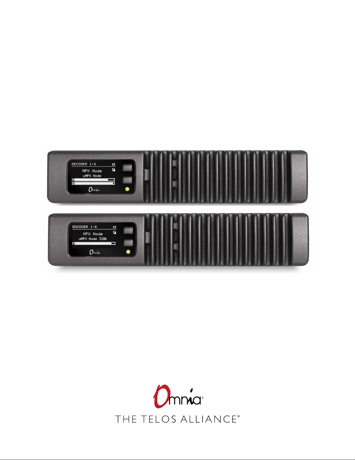
2001-00522-000 OMNIA MPX NODE DECODER
2001-00529-000 OMNIA MPX NODE ENCODER
TelosAlliance.com
P/N: 1490-00211-001 --- OMNIA MPX NODE MANUAL

Creating the Most Exciting and Engaging
Audio Experiences Imaginable
Congratulations on your new Telos Alliance product!
The gang here at Telos is committed to shaping the future of audio by delivering innovative, intuitive
solutions that inspire our customers to create the most exciting and engaging audio experiences imaginable.
We’re grateful that you have chosen audio tools from Telos® Systems, Omnia® Audio, Axia® Audio,
Linear Acoustic®, 25-Seven Systems®, and Minnetonka Audio®. We’re here to help you make your
work truly shine. We hope that you enjoy your Telos Alliance product for many years to come and won’t
hesitate to let us know if we can help in any way.
The Telos Alliance

Table of Contents
UserWarnings and Cautions . . . . . . . . . . . . . . . . . . . . . . . . .VII
We support you… . . . . . . . . . . . . . . . . . . . . . . . . . . . . . IX
Warranty. . . . . . . . . . . . . . . . . . . . . . . . . . . . . . . . . . X
1 Introduction 1
Overview. . . . . . . . . . . . . . . . . . . . . . . . . . . . . . . . . . 1
About the MPX Codec . . . . . . . . . . . . . . . . . . . . . . . . . . . 1
A Distinction from L/ R signals . . . . . . . . . . . . . . . . . . . . . . . . 2
2 Quick Start Instructions 3
Obtaining an IP address . . . . . . . . . . . . . . . . . . . . . . . . . . . 3
Logging In . . . . . . . . . . . . . . . . . . . . . . . . . . . . . . . . . 4
3 Use Cases & Applications 6
Simple STL: Use with Any FM Processor . . . . . . . . . . . . . . . . . . . . 6
Omnia 9 as MPX Encoder. . . . . . . . . . . . . . . . . . . . . . . . . . . 6
One Processor to Many Transmitters. . . . . . . . . . . . . . . . . . . . . . 7
Use with private networks, and IP radios . . . . . . . . . . . . . . . . . . . 7
4 Redundant Paths and Backup Scenarios 8
Dual Encoder, Single Decoder. . . . . . . . . . . . . . . . . . . . . . . . . 8
Dual Encoder, Dual Decoder . . . . . . . . . . . . . . . . . . . . . . . . . 8
5 The Front Panel 9
Front Panel buttons . . . . . . . . . . . . . . . . . . . . . . . . . . . . . 9
Front Panel indicator LED . . . . . . . . . . . . . . . . . . . . . . . . . .10
OLED Display (Encoder) . . . . . . . . . . . . . . . . . . . . . . . . . . . 11
OLED Display (Decoder) . . . . . . . . . . . . . . . . . . . . . . . . . . . 12
Encoder and Decoder page descriptions . . . . . . . . . . . . . . . . . . . . 13

6 User Prole 14
User Information . . . . . . . . . . . . . . . . . . . . . . . . . . . . . . 14
Name . . . . . . . . . . . . . . . . . . . . . . . . . . . . . . . . . 14
Email. . . . . . . . . . . . . . . . . . . . . . . . . . . . . . . . . . 14
Username . . . . . . . . . . . . . . . . . . . . . . . . . . . . . . .14
Password . . . . . . . . . . . . . . . . . . . . . . . . . . . . . . . . 15
Update Prole . . . . . . . . . . . . . . . . . . . . . . . . . . . . . . .15
Logging In for the rst time . . . . . . . . . . . . . . . . . . . . . . . . .15
Password & Cong Reset. . . . . . . . . . . . . . . . . . . . . . . . . . . 16
Logout. . . . . . . . . . . . . . . . . . . . . . . . . . . . . . . . . . . 16
7 Using the GUI 17
GUI Tips . . . . . . . . . . . . . . . . . . . . . . . . . . . . . . . . . .17
8 System Setup 19
Network Setup . . . . . . . . . . . . . . . . . . . . . . . . . . . . . . . 20
Net Mode. . . . . . . . . . . . . . . . . . . . . . . . . . . . . . . . 20
Network Address . . . . . . . . . . . . . . . . . . . . . . . . . . . .20
Network Mask . . . . . . . . . . . . . . . . . . . . . . . . . . . . .20
Network 1 & 2 Gateway . . . . . . . . . . . . . . . . . . . . . . . . .21
DNS Server . . . . . . . . . . . . . . . . . . . . . . . . . . . . . . . 21
SAVE . . . . . . . . . . . . . . . . . . . . . . . . . . . . . . . . . . 21
Hostname . . . . . . . . . . . . . . . . . . . . . . . . . . . . . . . . . 22
Updating Firmware . . . . . . . . . . . . . . . . . . . . . . . . . . . . . 22
System Settings. . . . . . . . . . . . . . . . . . . . . . . . . . . . . . . 23
System Location. . . . . . . . . . . . . . . . . . . . . . . . . . . . . 23
Syslog Server IP . . . . . . . . . . . . . . . . . . . . . . . . . . . . . 23
Web Server Port . . . . . . . . . . . . . . . . . . . . . . . . . . . . . 24
OLED Timeout . . . . . . . . . . . . . . . . . . . . . . . . . . . . . . 24
Save . . . . . . . . . . . . . . . . . . . . . . . . . . . . . . . . . . 25
Reboot. . . . . . . . . . . . . . . . . . . . . . . . . . . . . . . . . . . 25

9 Encoder Setup 26
µMPX (MicroMPX) Encoder Settings. . . . . . . . . . . . . . . . . . . . . . 27
MPX Input Level . . . . . . . . . . . . . . . . . . . . . . . . . . . . . .27
Clip Indicator . . . . . . . . . . . . . . . . . . . . . . . . . . . . . . . . 28
Bitrate . . . . . . . . . . . . . . . . . . . . . . . . . . . . . . . . . . . 28
Streams . . . . . . . . . . . . . . . . . . . . . . . . . . . . . . . . . . 28
Stream Error Correction . . . . . . . . . . . . . . . . . . . . . . . . . . . 29
Keyframe interval . . . . . . . . . . . . . . . . . . . . . . . . . . . . . . 30
Error Correction size/delay . . . . . . . . . . . . . . . . . . . . . . . . . . 30
Error Correction Overhead . . . . . . . . . . . . . . . . . . . . . . . . . . 30
Rate Limiter (On/O) . . . . . . . . . . . . . . . . . . . . . . . . . . . . 31
Limit Rate Below . . . . . . . . . . . . . . . . . . . . . . . . . . . . . . 31
Encoder Dashboard . . . . . . . . . . . . . . . . . . . . . . . . . . . . . 32
10 Decoder Setup 34
µMPX (MicroMPX) Decoder Settings. . . . . . . . . . . . . . . . . . . . . . 34
MPX Output Level . . . . . . . . . . . . . . . . . . . . . . . . . . . . . . 36
Stream Receiver. . . . . . . . . . . . . . . . . . . . . . . . . . . . . . . 36
Stream Delay . . . . . . . . . . . . . . . . . . . . . . . . . . . . . . . . 37
Test Signal . . . . . . . . . . . . . . . . . . . . . . . . . . . . . . . .37
Decoder Dashboard . . . . . . . . . . . . . . . . . . . . . . . . . . . . . 37
Dashboard Meter Section . . . . . . . . . . . . . . . . . . . . . . . . . .38
Data Stream Display. . . . . . . . . . . . . . . . . . . . . . . . . . . . . 39
Waveform and MPX displays . . . . . . . . . . . . . . . . . . . . . . . . . 40
Dashboard: Unit Status . . . . . . . . . . . . . . . . . . . . . . . . . . .40
Dashboard: MPX Receiving Status . . . . . . . . . . . . . . . . . . . . . . 40
11 GPIO 41
Encoder GPIO Functions . . . . . . . . . . . . . . . . . . . . . . . . . . . 42
Decoder GPIO Functions . . . . . . . . . . . . . . . . . . . . . . . . . . . 42

12 Rear Panel 44
Composite . . . . . . . . . . . . . . . . . . . . . . . . . . . . . . . . . 44
GPIO. . . . . . . . . . . . . . . . . . . . . . . . . . . . . . . . . . . . 44
NET1. . . . . . . . . . . . . . . . . . . . . . . . . . . . . . . . . . . . 45
NET2 . . . . . . . . . . . . . . . . . . . . . . . . . . . . . . . . . . .45
12VDC Input . . . . . . . . . . . . . . . . . . . . . . . . . . . . . . . . 45
13 Internal Switch Settings 46
DIP-switch Access . . . . . . . . . . . . . . . . . . . . . . . . . . . . . . 46
Identifying Switches. . . . . . . . . . . . . . . . . . . . . . . . . . . . . 47
Encode / Decode Mode (Switch bank 1) . . . . . . . . . . . . . . . . . . . . 47
Impedance / Gain (Switch bank 2) . . . . . . . . . . . . . . . . . . . . . .48
14 Technical Notes 49
Firewall and Security . . . . . . . . . . . . . . . . . . . . . . . . . . . .49
Tilt Correction. . . . . . . . . . . . . . . . . . . . . . . . . . . . . . . . 49
Cooling . . . . . . . . . . . . . . . . . . . . . . . . . . . . . . . . . .49
15 Rack Mounting 50
Rack Mount kit . . . . . . . . . . . . . . . . . . . . . . . . . . . . . . . 50
Short rack ear . . . . . . . . . . . . . . . . . . . . . . . . . . . . . . 50
Long rack ear . . . . . . . . . . . . . . . . . . . . . . . . . . . . . . 50
Revision 2 “L”bracket (p/n 1771-00128) . . . . . . . . . . . . . . . . . . 51
Single MPX Node . . . . . . . . . . . . . . . . . . . . . . . . . . . . . . 51
Double MPX Node. . . . . . . . . . . . . . . . . . . . . . . . . . . . . . 51
Revision 2 Hardware. . . . . . . . . . . . . . . . . . . . . . . . . . . . . 52
Revision 1 Hardware. . . . . . . . . . . . . . . . . . . . . . . . . . . . . 53
16 Specications 54
External power supply. . . . . . . . . . . . . . . . . . . . . . . . . . . . 54
MPX Node Power Consumption: . . . . . . . . . . . . . . . . . . . . . . .54
MPX Node Composite Input/Output: . . . . . . . . . . . . . . . . . . . . .54
Operating Temperatures . . . . . . . . . . . . . . . . . . . . . . . . . . . 54
Dimensions and Weight . . . . . . . . . . . . . . . . . . . . . . . . . . . 55

V1.1-OCTOBER 2019 | VII
OMNIA MPX NODE MANUAL
User Warnings and Cautions
The installation and service instructions in this manual are for use by qualified personnel
only. To avoid electric shock, do not perform any servicing other than that contained in
the operating instructions unless you are qualified to do so. Refer all servicing to qualified
personnel.
This instrument has an autoranging line voltage input. Ensure the power voltage is within
the specified range of 100-240VAC. The ~ symbol, if used, indicates an alternating current
supply.
This symbol, wherever it appears, alerts you to the presence of uninsulated, dangerous
voltage inside the enclosure – voltage which may be sufficient to constitute a risk of shock.
This symbol, wherever it appears, alerts you to important operating and maintenance
instructions. Read the manual.
CAUTION: HAZARDOUS VOLTAGES
The instrument power supply may incorporate an internal fuse. Hazardous voltages may
still be present on some of the primary parts even when the fuse has blown. If fuse replace-
ment is required, replace fuse only with same type and value for continued protection
against fire.
WARNING:
The product’s power cord is the primary disconnect device. The socket outlet should be
located near the device and easily accessible. The unit should not be located such that
access to the power cord is impaired. If the unit is incorporated into an equipment rack,
an easily accessible safety disconnect device should be included in the rack design.
To reduce the risk of electrical shock, do not expose this product to rain or moisture. This
unit is for indoor use only.
This equipment requires the free flow of air for adequate cooling. Do not block the venti-
lation openings on the rear and sides of the unit. Failure to allow proper ventilation could
damage the unit or create a fire hazard. Do not place the units on a carpet, bedding, or
other materials that could interfere with any panel ventilation openings.
If the equipment is used in a manner not specified by the manufacturer, the protection
provided by the equipment may be impaired.

V1.1-OCTOBER 2019 | VIII
OMNIA MPX NODE MANUAL
USA CLASS A COMPUTING DEVICE INFORMATION TO USER
WARNING:
This equipment generates, uses, and can radiate radio-frequency energy. If it is not
installed and used as directed by this manual, it may cause interference to radio com-
munication. This equipment complies with the limits for a Class A computing device,
as specified by FCC rules, part 15, subpart j, which are designed to provide reasonable
protection against such interference when this type of equipment is operated in a com-
mercial environment. Operation of this equipment in a residential area is likely to cause
interference. If it does, the user will be required to eliminate the interference at the user’s
expense. Note: objectionable interference to TV or radio reception can occur if other
devices are connected to this device without the use of shielded interconnect cables. FCC
rules require the use of shielded cables.
CANADA WARNING:
“This digital apparatus does not exceed the Class A limits for radio noise emissions set out
in the radio interference regulations of the Canadian department of communications.”
“Le présent appareil numérique n’émet pas de bruits radioélectriques dépassant les
limites applicables aux appareils numériques (de Class A) prescrites dans le règlement
sur le brouillage radioélectrique édicté par le ministère des communications du Canada.”
CE CONFORMANCE INFORMATION:
This device complies with the requirements of the EEC council directives:
93/68/EEC (CE MARKING)
73/23/EEC (SAFETY – LOW VOLTAGE DIRECTIVE)
89/336/EEC (ELECTROMAGNETIC COMPATIBILITY)
Conformity is declared to those standards: EN50081-1, EN50082-1.

V1.1-OCTOBER 2019 | IX
OMNIA MPX NODE MANUAL
Trademarks, Patents, and Licenses
Omnia is a trademark of TLS Corp. All other trademarks are the property of their
respective holders.
All versions, claims of compatibility, trademarks, etc. of hardware and software products
not made by The Telos Alliance which are mentioned in this manual or accompanying ma-
terial are informational only. The Telos Alliance makes no endorsement of any particular
product for any purpose, nor claims any responsibility for operation or accuracy. We reserve
the right to make improvements or changes in the products described in this manual which
may affect the product specifications, or to revise the manual without notice.
This document and its content are copyrighted by TLS Corporation and may not be
copied, reproduced, or distributed in any form without expressed written permission.
Patent information can be found at TelosAlliance.com/legal
Updates
MPX Node features and operations are determined largely by software. The Telos Alliance
strives to provide the most stable and feature-rich software available. We encourage you
to check for software updates from time to time by visiting our website or by contacting us
directly.
Feedback
We welcome feedback on any aspect of our products or this manual. In the past, many
good ideas from users have made their way into software revisions or new products.
Please contact us with your comments or suggestions.
We support you…
By Phone/Fax
You may reach our Telos Support Team in emergencies by calling +1 216-622-0247. For
billing questions or other non-emergency technical questions, call +1 216-241-7225
between 9:00 AM to 5:00 PM USA Eastern Time, Monday through Friday.
By Email
Non-emergency technical support is available at Support@TelosAlliance.com.

V1.1-OCTOBER 2019 | X
OMNIA MPX NODE MANUAL
By Web
The Omnia Web site has a variety of information that may be useful for product selection
and support. The URL is TelosAlliance.com/Omnia .
Service
You must contact Telos Alliance before returning any equipment for factory service. We
will need your unit’s serial number, located on the back of the unit. We will issue a return
authorization number, which must be written on the exterior of your shipping container.
Please do not include cables or accessories unless specifically requested by the Technical
Support Engineer. Be sure to adequately insure your shipment for its replacement value.
Packages without proper authorization may be refused. US customers, please contact
Telos Alliance Technical Support at +1-216-622-0247. All other customers should contact
local representative to make arrangements for service.
Warranty
For the latest Telos Alliance warranty, visit: telosalliance.com/warranty
Register your product
Register your product today to get the full benefits of our warranty, support, and product
updates. telosalliance.com/product-registration/
The Telos Alliance
1241 Superior Ave. Cleveland, OH 44114 USA
+1 (216) 241-7225
For Telos Support:
24/7 telephone: +1 (216) 622-0247
Email: [email protected]
Web: telosalliance.com/support-request

V1.1-OCTOBER 2019 | 1
OMNIA MPX NODE MANUAL
1 Introduction
Overview
The Omnia MPX Node is a purpose-built broadcast codec for transporting FM composite
(MPX) signals over IP networks. Like its namesake (the classic Axia xNode), Omnia
MPX Node is a building block technology that helps stations leverage the growing power
and capability of data networking. By transporting an FM composite signal rather than
Left/Right audio, broadcasters can keep their on-air processing and RDS encoding at the
studio, then deliver a transmission-ready, peak controlled FM multiplex signal directly
to an FM transmitter without the need for transmitter-side peak limiting or stereo
generation. Since MPX is transported over IP, signals are routable, and one-to-many
distribution of “carbon copy” processing becomes possible. Each MPX Node can be set
to either encode or decode, and a pair of units creates an end-to-end system. Omnia SST
users can connect to the MPX Node, and stations with an Omnia 9 processor can purchase
an Encoder license, such that MPX over IP signals can be sent directly via IP from the
processor to a decoder.
About the μMPX Codec
MPX Node utilizes μMPX ("micro" MPX), a specially designed audio codec pur-
pose-built for FM radio that is able to transport high-quality Multiplexed FM signals over
a relatively small 320kbps data pipe using UDP. While some companies have full-band-
width “linear” MPX over IP offerings, distribution of such streams requires extremely
high dedicated bandwidth, typically 2 megabits (Mb) or more. μMPX slashes the amount
of bandwidth needed for distribution by nearly 84% to a remarkable 320kbps. By reducing
data requirements, high-quality multiplexed audio can be economically routed from
any audio processor, over IP, and directly into an exciter. Unlike codec offerings that are
designed explicitly for stereo audio (MP3, AAC, etc), μMPX is purpose built for com-
posite FM signals. μMPX uses a unique perceptual masking strategy, leveraging the native
properties of FM multiplexed signals. For STL use, this approach provides a double
benefit over stereo audio codecs because:

V1.1-OCTOBER 2019 | 2
OMNIA MPX NODE MANUAL
1. Coding artifacts produced by stereo codecs require additional processing (post
transport) to correct overshoots and other errors prior to stereo generation.
2. Artifacts occurring in μMPX coding manifest as FM noise and go unnoticed.
With μMPX, lower bandwidth IP connections and narrow band STL channels can now be
used to transport MPX signals. μMPX will create new audio distribution options and cut
equipment needs and costs, as it leverages advances in the world’s ever-growing IP infra-
structure. Sound quality also benefits as this purpose-built codec makes its way into more
places. As with all new groundbreaking technologies, potential applications for μMPX
will only grow as creative radio engineers begin utilizing it. Watch for μMPX to make its
way into an increasing number of Omnia products.
A Distinction from L/ R signals
An important concept for all readers to understand is that MPX Node transports modulat-
ed FM signals, not L/R audio. This modulated signal contains the components that make
up an FM broadcast; L+R, 19kHz stereo pilot, L-R and RDS/RBDS at the first subcarrier.
As an encoder, MPX Node converts composite analog FM to IP packets; as a decoder, it
converts packets to analog composite FM. As such, the Encoder version needs to be fed by
the output of an audio processor, while the decoder is intended to feed the analog compos-
ite input of an FM transmitter. In some ways, MPX Node may be thought of as a modem
for FM signals. For reference, a diagram of FM signal is useful.
V1.1-OCTOBER 2019 | 3
OMNIA MPX NODE MANUAL
2 Quick Start Instructions
MPX Node is a computing appliance that interfaces to audio processing and FM transmis-
sion equipment. Installation and proper operation requires you have some basic knowl-
edge of computer networking, firewalls, port management, and other general computer
skills, in addition to your radio broadcast knowledge.
You are probably anxious to get your MPX Node(s) running. This section will help you
get going.
MPX Nodes are controlled through an HTML5 web interface. In order to access this
interface you need to log on to the unit by entering its IP address in a (modern) browser
(our developers use Chrome for product testing). For convenience, both Encoder and
Decoder nodes are set from the factory to obtain get IP addresses using DHCP.
Obtaining an IP address
1. Plug your MPX Node into a network providing DHCP (either Net1 or Net2 ports can
be used, but you should use Net1 as your primary).
2. Power your unit up
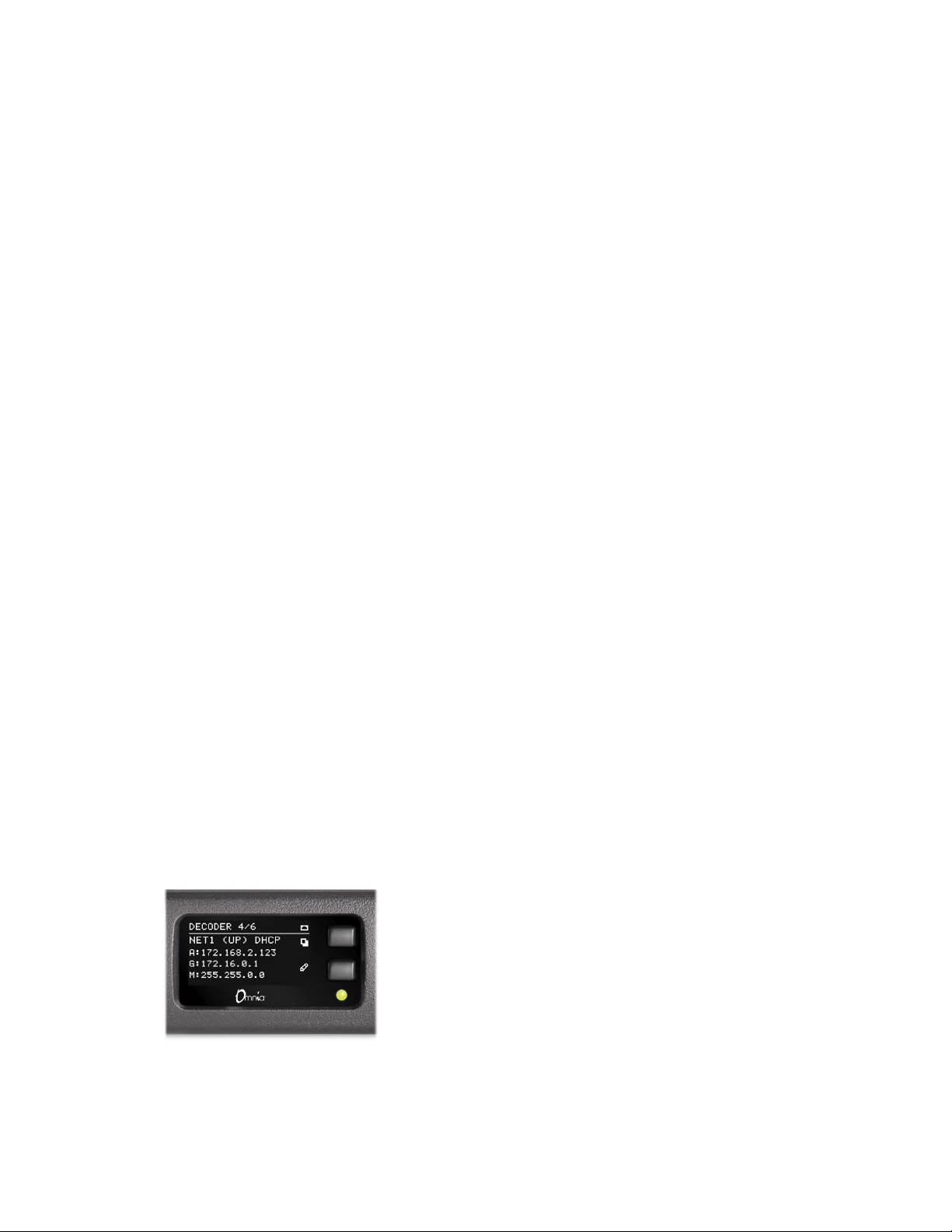
3. Using the top control button on the front panel, scroll through the display pages to
the Network port connected to your router. You should see an (up) indication, and a
DHCP assigned IP address. In our example below, the network is plugged into Net1.
(UP) indicates that your network is connected while (DN) indicates it is down.

V1.1-OCTOBER 2019 | 4
OMNIA MPX NODE MANUAL
4. If you don’t have a DHCP server on your network, you can enter a static IP address from
the front panel. Press and hold the bottom front panel button for 10 seconds until you
see the Setup page.
5. Use the upper front panel button to change values, and the lower button to advance to
the next field. To save changes, advance to the SAVE field and press the upper button.
6. Once your MPX Node has a valid IP address, use a connected web browser to log in by
entering it in the address bar:
Logging In
Once you enter the IP address of your unit in a connected browser, you will see the follow-
ing login page:

V1.1-OCTOBER 2019 | 5
OMNIA MPX NODE MANUAL
The factory default user name is user, the default password is also user.
♦Once you enter this default, you will see the User Profile page. You must enter and save
a new, unique password in order to access other control pages.
♦For security, a password must meet the following requirements:
¸Length must be 8 characters or more
¸It must contain one or more uppercase letters
¸It must contain one or more lowercase letters
¸It must contain one or more numbers
¸It must contain one or more special characters, eg: ! @ # $ % ^ & * ? _ ~ £
♦User and password names are case sensitive. Beware that some browsers and devices will
attempt to capitalize the first letter in a field, possibly entering in a wrong character.
♦The password entry dialog will indicate if your password meets requirements:
♦Be sure to write your new user/password combination down. We suggest you text or
email it to yourself.
♦If you forget or misplace your user/password, you can reset it to the user / user default
from the front panel. For more information check Password Reset in the User Profile
section of this manual.
Once you log into your MPX Node, click through the selections on the upper left side of
the user interface and have a look at the various setup pages of the unit. We’re sure you’ll
find the displays and controls easy to understand and use.
V1.1-OCTOBER 2019 | 6
OMNIA MPX NODE MANUAL
3 Use Cases & Applications
These diagrams provide a quick snapshot of some of the ways MPX nodes can be used.
This list is just a fraction of potential applications for this building block technology. MPX
Node can help simplify your transmitter rack, eliminating the need for further processing
or stereo generation at the transmitter.
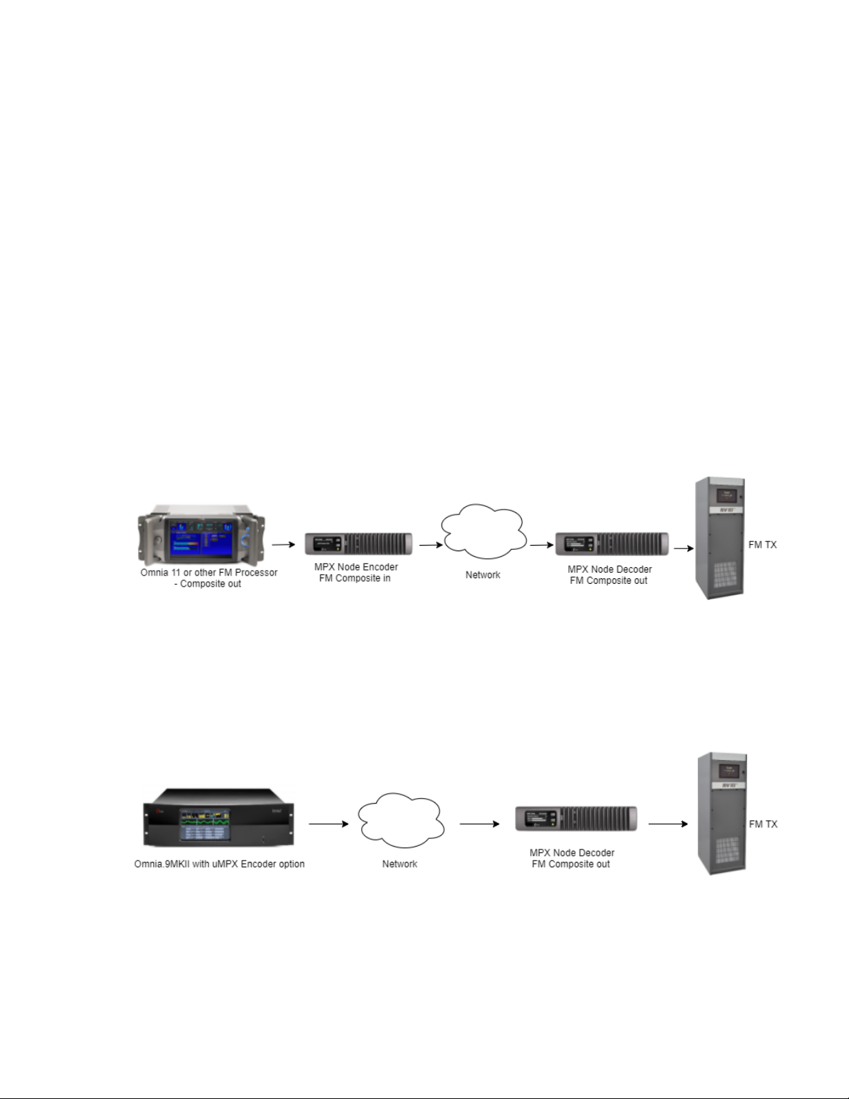
Simple STL: Use with Any FM Processor
MPX Node is processor agnostic. Composite output of ANY brand of FM processor feeds
an MPX Node Encoder, while the Decoder feeds the transmitter .
Omnia 9 as MPX Encoder
Now your processor IS the front end of your STL! With Encoding built right into the
Omnia 9, a network connection, and a single or multiple decoder nodes, your setup just
got less complicated, and your processor can now move back to the studio.
V1.1-OCTOBER 2019 | 7
OMNIA MPX NODE MANUAL
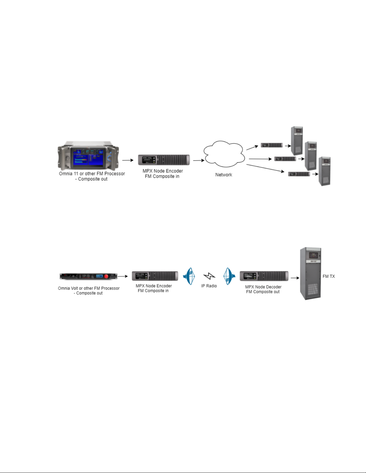
One Processor to Many Transmitters
This diagram gets at one of the primary benefits of MPX over IP: each decoder is a “carbon
copy” of the main processor. Main sites, backups and repeaters all get the same signal.
This leverages the value of your best processor, creates sonic uniformity at all TX sites,
and means you don’t have to tweak and adjust each transmission chain!
Use with private networks, and IP radios
With μMPX, lower bandwidth IP connections and narrow band STL channels can now be
used to transport MPX signals.

V1.1-OCTOBER 2019 | 8
OMNIA MPX NODE MANUAL
4 Redundant Paths and Backup Scenarios
Dual Encoder, Single Decoder
In this illustration, a processor feeds two Encoders. Both Encoders send the same signal
over UDP to a single Decoder at the same IP and port address. If one of the links fails, the
Decoder picks up the stream from the other Encoder after a brief failover period. (An
external router may be required, depending on your link design).
Dual Encoder, Dual Decoder
In this illustration, a second Decoder is added to the above so that both Main and Backup
transmitters are both fed with signals served by separate network paths. (An external
router may be required, depending on your link design).

V1.1-OCTOBER 2019 | 9
OMNIA MPX NODE MANUAL
5 The Front Panel
The MPX Node front panel consists of two buttons, an LED and a long-life OLED display,
housed in a fanless, rugged cast aluminum body with integrated heat exchanger. The
front panel provides fast access to system status information. Front panel data input is
limited to IP address setup and password reset so you can get at the GUI , the real control
point for all system operation.
Front Panel buttons
Use the top control button to scroll through the display pages. Page 4 (the NET1 page)
may be edited, by pressing and holding the bottom button for 10 seconds until the IP
address edit page appears. Once you are in this screen, the top button changes values
while the bottom will advance you to the next field.
V1.1-OCTOBER 2019 | 10
OMNIA MPX NODE MANUAL
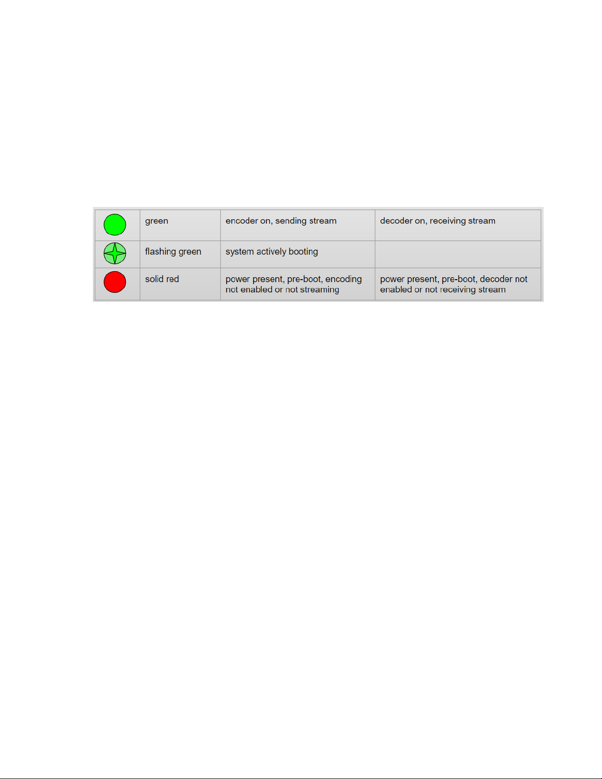
Front Panel indicator LED
The front panel indicator LED provides quick “at-a glance” status information about your
MPX Node. Normally, this LED will be steady green, indicating your unit has properly
started and is encoding or decoding normally. Red indicates the unit has not finished
startup, is not connected to a network, or is not encoding or decoding.
Be aware that if audio programming has stopped somewhere else in the airchain and only
silence is being fed to the encoder, the LED will be lit green since the connection is still
live, and a signal (encoded noise-floor audio) is being passed. The MPX level displays on
the screen will indicate that the MPX level is very low.
This manual suits for next models
2
Table of contents


