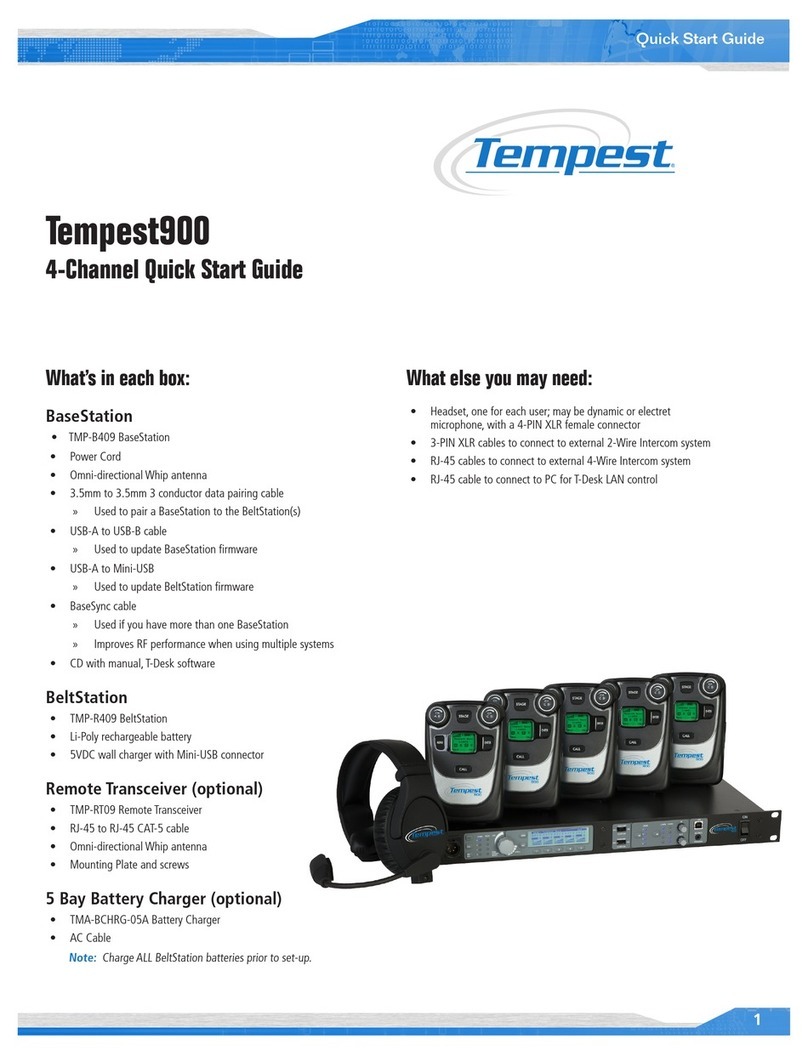
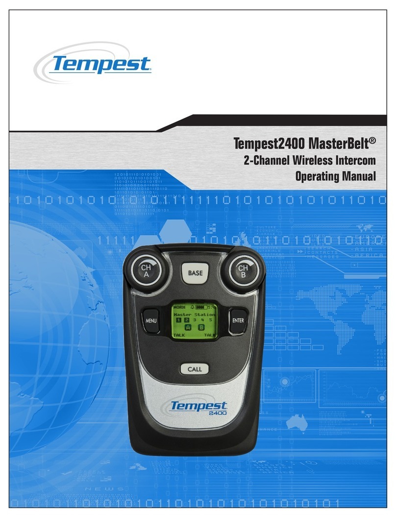
Tempest 900 User manual

Tempest900
2-Channel Wireless Intercom
Operating Manual


Thank You
We at CoachComm want to thank you for purchasing a Tempest®900 Wireless Intercom System. We have made every effort to build
a reliable, intuitive wireless intercom system that provides the same functionality that you expect from your hard-wired intercom
equipment.
One of our goals in the design of Tempest was that it should work the way you think it should work – that is, it should be intuitive and
similar to other equipment that you may already use. You will be able to begin using your new Tempest wireless intercom system with
nothing more than the Quick Start Guide. However, to fully benet from the available features, please read this manual carefully.
We want Tempest to make your job easier and your experience to be positive. To successfully familiarize yourself with the many diverse
and powerful features Tempest offers, it is crucial that you acquaint yourself with the manual. Your time spent will help you get the most
from your Tempest wireless intercom by making setup easier.
We are committed to providing you with a high quality product that will deliver years of trouble-free service. Should you experience any
problem with your Tempest equipment, whether it is a warranted problem or service after you have owned the system for several years,
we will be there to take care of you.
Thank you for choosing Tempest for your wireless intercom needs.

ii
Tempest900 2-Channel Operating Manual
Tempest900 2-Channel Wireless Intercom Operating Manual
D0000151
TM9002CHManual_D0000151_B
Legal Information
CoachComm, LLC
Tempest®
205 Technology Parkway
Auburn, AL 36830
www.tempestwireless.com
1.844.475.4268 or +1.334.321.1160
COPYRIGHT © 2015 CoachComm, LLC. All rights reserved. CoachComm® and the Tempest® logos are registered trademarks of CoachComm,
LLC. Any and all other trademark references within this document are property of their respective owners.
This document /content contains proprietary information which is protected by copyright. No part of this document and/or content may be
transcribed, distributed, stored, translated into any language or computer language, copied, reverse engineered, reproduced, or transferred in
other form whatsoever without the previous express written approval of CoachComm, LLC.
The software described in this document is furnished under a license agreement and may be used only in accordance with the terms of the
agreement.
In no event shall CoachComm, LLC. be held liable for any loss, expenses, or damages of any kind whatsoever, whether direct, indirect, incidental,
or consequential arising from the use of this product or the support materials provided with the product. We have done our utmost to ensure
that the information in this user guide is complete, accurate and up-to-date. No warranties are made, either expressed or implied, with regard
to the contents of this work, its merchantability, or tness for a particular use. CoachComm, LLC assumes no responsibility for errors and
omissions or for the uses made of the material contained herein or reader decisions based on such use. No warranties are provided for changes
to third-party equipment, which could be referred to in this guide and will have no effect on the applicability of the information provided within.
The author reserves all rights, including the right to reproduce this guide in full or part in any form. The content is subject to change without
prior notication. The product is subject to technical change without prior notication.
www.tempestwireless.com

iii
Tempest900 2-Channel Operating Manual
Table of Contents
Important Safety Instructions................................................................................................................................................ 1
A/C Power Warning .............................................................................................................................................................. 2
Battery Safety....................................................................................................................................................................... 3
Maintenance and Care ......................................................................................................................................................... 4
Quick Start Guide................................................................................................................................................................. 5
Theory of Operation.............................................................................................................................................................. 7
What’s In Each Box .............................................................................................................................................................. 9
Accessory Items You May Require ...................................................................................................................................... 10
BaseStation Overview......................................................................................................................................................... 11
BeltStation Overview.......................................................................................................................................................... 18
Transceiver Controls ........................................................................................................................................................... 21
BaseStation Setup .............................................................................................................................................................. 22
Remote Transceiver ............................................................................................................................................................ 26
Congure the BaseStation.................................................................................................................................................. 28
Modes of Operation ........................................................................................................................................................... 54
Connecting Multiple BaseStations....................................................................................................................................... 56
How Do I …? .................................................................................................................................................................... 63
Troubleshooting ................................................................................................................................................................. 67
Default Settings.................................................................................................................................................................. 71
Tempest Part Numbers ....................................................................................................................................................... 72
System Features ................................................................................................................................................................. 73
900 MHz System Specications* ...................................................................................................................................... 74
BaseStation Specications* ................................................................................................................................................ 75
BeltStation Specications* .............................................................................................................................................. 76
Remote Transceiver Specications* ..................................................................................................................................... 76
Glossary............................................................................................................................................................................. 77
Radio Compliance .............................................................................................................................................................. 79
Warranty Information ......................................................................................................................................................... 81
Technical Support............................................................................................................................................................... 82
Tempest Block Diagram ...................................................................................................................................................... 84
Index ................................................................................................................................................................................. 86
*Notice About Specications
While CoachComm makes every attempt to maintain the accuracy of the information contained in this manual, this information is subject to
change without notice. Please check our website for the latest system specications and certications.

iv
Tempest900 2-Channel Operating Manual
This page is intentionally blank.

1
Tempest900 2-Channel Operating Manual
Important Safety Instructions
The word “Caution” is the lowest of the three signal words (Caution, Warning and Danger), with “Danger” being the highest. Therefore,
whenever the word “Caution” is used, it may be replaced with either of the higher rated signal words: “Warning” or “Danger.”
• DANGER – indicates a situation which, when not avoided, results in death or severe injury;
• WARNING – indicates a situation which, when not avoided, has the potential to result in death or severe injury;
• CAUTION – indicates a situation which, when not avoided, results or has the potential to result in minor injury.
1. Read these instructions.
2. Follow all instructions.
3. Heed all warnings.
4. Keep these instructions.
WARNING – To reduce the risk of re or electric shock, do not expose this apparatus to rain or moisture.
Do not use this apparatus near water.
Do not expose the apparatus to dripping or splashing. Do not place objects lled with liquids, such as vases, on the apparatus.
The BaseStation shall be connected to a main socket outlet having a protective earthing connection.
Install the BaseStation so that the appliance coupler (AC power inlet) is readily accessible and operable. Clean only with a dry cloth.
Install in accordance with manufacturer’s instructions.
Do not install near any heat sources such as radiators, heat registers, stoves, or other apparatus (including ampliers) that produce heat.
Do not defeat the safety purpose of the polarizing or grounding type plug. A polarized plug has two blades with one wider than the other. A
grounding type plug has two blades and a third grounding prong. The wide blade or third prong is provided for your safety. When the provided
plug does not t into your outlet, consult an electrician for replacement of the obsolete outlet.
Protect the power cord from being walked on or pinched, particularly at plugs, convenience receptacles, and the point where they exit the
apparatus.
Only use attachments/accessories specied by the manufacturer.
Unplug this apparatus during lightning storms or when unused for long periods of time.
Refer all servicing to qualied service personnel. Servicing is required when the apparatus has been damaged in any way, for example if the
power-supply cord has been damaged, liquid has been spilled or objects have fallen into the apparatus, or if the apparatus has been exposed to
rain or moisture, does not operate normally, or has been dropped.

2
Tempest900 2-Channel Operating Manual
A/C Power Warning
Users should exercise extreme care when working with electricity. Additional care should be used when
working with electricity outdoors in inclement weather. When working outdoors or near water, always
connect the system into a ground-fault interrupting circuit.
There are no user-serviceable parts inside the Tempest BaseStation, Transceiver, or BeltStation. Opening the case may expose dangerous
electrical components, and will void the warranty.
ALERT SYMBOL – Indicates important information.
CAUTION SYMBOL – Indicates a potential to damage equipment.
DANGER SYMBOL – indicates a potential safety hazard.

3
Tempest900 2-Channel Operating Manual
Battery Safety
Battery Transportation
Rechargeable lithium batteries are subject to special regulation by U.S. and International
laws, particularly regarding transportation on passenger aircraft. However, individual
batteries installed in consumer electronics are not restricted, provided there are only
the correct numbers and types of batteries as may be needed to operate the electronic
equipment.
Your Tempest Wireless Intercom System includes rechargeable lithium-polymer batteries that power the BeltStations. To ensure that there is no
violation of U.S. or International laws, and to ensure your own safety, always:
• Transport rechargeable lithium batteries installed in the equipment they are intended to power.
• Transport spare batteries in a padded case, separated from one another.
• Never transport your rechargeable lithium batteries bundled together.
• Never transport more than 12 lithium batteries in a single package.
Lithium-polymer batteries include a chemistry that is intended to overcome the dangers associated with lithium ion batteries. In addition, the
batteries that accompany your Tempest Wireless system include protective circuits to further reduce the possibility of a dangerous reaction
associated with charging or discharging beyond safe limits. With reasonable care you can expect many years of safe and reliable power from
your batteries.
Tempest batteries are not subject to transport regulations of dangerous goods because they fulll the following regulatory provisions:
• ADR 188
• IATA A45
• IMDG 188
Battery Storage
Long-term storage of batteries at maximum charge can result in permanent loss of capacity.
For long term storage of batteries, charge/discharge the batteries to approximately 60% of capacity. Batteries stored for longer than one year
should be recharged to 60% annually.
Trickle charging is not recommended due to the very low self discharge rate of the batteries.
As with all batteries:
• Do not burn.
• Do not expose batteries to excessive heat such as sunshine, re or other heat sources.
• CAUTION – Danger of explosion if battery is incorrectly replaced. Replace only with the same or equivalent type.
• Properly dispose of used batteries promptly.
• Keep away from children.

4
Tempest900 2-Channel Operating Manual
Maintenance and Care
Cleaning
Generally, the Tempest Wireless hardware should be cleaned only with a dry cloth. A soft cloth with rubbing alcohol may be used to wipe the
units if needed. Never spray solvents or chemicals onto the units.
Because of Tempest’s weather resistant design, it is not highly susceptible to dust or airborne contaminants. However, all electronic devices can
be susceptible to particulate contamination. If exposed to an extremely dusty environment, contact an authorized Tempest service center for
internal cleaning.
Temperature and Humidity
Ideally, all electronics should be stored and used in a controlled environment with moderate temperature and humidity. Tempest components are
designed to be very durable, and can tolerate a wide range of environmental conditions.
Install the BaseStation in a location where it will not be exposed to extreme weather conditions. Protect the unit against dust or moisture.
Always protect any AC power connections from the elements with safety in mind.
For more extreme environmental conditions, the BaseStation can remain in a secure location with antennas for the BaseStation located remotely
and connected by low-loss 50 ohm coax cable, or the optional Remote Transceiver can be used.
The Tempest Remote Transceiver is weather resistant, with gaskets intended to prevent moisture entry from the top and sides. The CAT-5 cable
connection on the bottom is not water tight. If it is to be used in an environment subject to blowing rain, snow, fog or high humidity, protect the
transceiver with a cover that will not interfere with the RF.
The BeltStations are designed to work wherever people work. While the BeltStation design is weather resistant, the headset XLR connector on
the bottom is not watertight. BeltStations should not be submerged in liquids. Protect the battery compartment from water when changing
batteries. The battery compartment offers a route to the electronic circuitry.

5
Tempest900 2-Channel Operating Manual
Quick Start Guide
What You Will Need
BaseStation
• Power cord
• One BaseStation antenna
• 3.5mm male-to-male mini-stereo pairing
cable
BeltStations
• Up to 5 per BaseStation
• Lithium-Polymer battery and
• Charger - 1 per BeltStation
Headsets (customer supplied)
• 1 per BeltStation
• 1 per BaseStation
1. Connect a whip antenna onto the back of the BaseStation.
Select a suitable location for the BaseStation. Tempest is a radio system, broadcasting and receiving RF signals that are affected by physical and
electronic barriers.
The antenna should be located as high as possible and away from all obstructions. When
using a whip (omnidirectional) antenna, select a location as close as possible to the center of
the area you want to cover.
Use alternative antenna options when the BaseStation is in a rack or other metal structure,
or stacked with other gear. Remote location antenna placement of up to 1,500 ft. can be
achieved using the Tempest Remote Transceiver (part # TMP-RT09). See the operating manual
for more details about antenna placement, recommended cable types, and other antenna
options.
2. Connect the power cord and Power On the BaseStation.
3. Install Batteries in BeltStations.
Install the Lithium-Polymer battery in each BeltStation. Be certain that the gold contacts on the
battery touch the contacts in the battery compartment. The battery is shipped with a partial charge, so
charging will be necessary before maximum run time will be achieved.
OR
Insert (3) AA alkaline batteries in the battery compartment. Always replace the battery cover.
To power ON the BeltStation, press and hold the power button for approximately two seconds. The
display will indicate “None Selected.” Turn the power OFF by holding the power button for four
seconds.
2 sec
POWER ON

6
Tempest900 2-Channel Operating Manual
4. Pair BeltStations to the BaseStation.
Pairing is a programming process that allows a BaseStation and BeltStation to recognize each other.
• Conrm that the BaseStation is powered ON.
• Conrm that the BeltStation is powered OFF.
• Connect the Pairing Cable from the BaseStation to a BeltStation.
• Power ON the BeltStation and watch the BeltStation display for “Pairing Complete.”
• BeltStation status will become visible on the BaseStation display.
• Repeat with each BeltStation.
5. Connect Headsets to BeltStations.
Plug a headset into each BeltStation, and the BaseStation if desired.
6. Operation.
Select a channel on the BeltStations by pressing the CH A or CH B control.
Press the TALK button. A quick press latches the Talk button for “Hands Free” operation. Press and hold
the Talk button for more than two seconds while you talk and the button will release in a Push-To-Talk
manner. A solid LED means that Talk is active. A ashing LED means that Talk is not active.
Set the volume by rotating the CH A or CH B control.
You may conrm BeltStation operation on the BaseStation Operation screen. There is a
section for each BeltStation. In this illustration, each BeltStation is set to talk on
channel A and listen on channels A & D, with only three BeltStations in operation.
A headset may be connected to the front of the Base Station. Activate by pressing the TALK button. Select a channel by pressing the volume
knob.
Refer to the operating manual for detailed instructions regarding:
• Country limitation on 900MHz RF spectrum.
• Adjusting the Network Number and Lockout Key.
• Assigning names for equipment.
• Charging batteries.

7
Tempest900 2-Channel Operating Manual
Theory of Operation
Tempest is a DSP (Digital Signal Processor) based, full duplex, wireless intercom system. It is a digital, point-to-point communications system,
operating in 26 MHz of spectrum in the 900MHz frequency band. This band allows users to operate with no license requirements in most
locations.
The 900MHz band offers many benets. There are, however, a wide variety of technologies and users competing for clear spectrum in this limited
band. Tempest utilizes patented and proprietary technologies to ensure a robust and reliable RF link under a wide variety of physical and RF
environments. This level of reliability is the most important attribute of any wireless system.
Tempest utilizes proprietary, Frequency Hopping Spread Spectrum (FHSS) technology that has seven U.S. patents. Multiple BeltStation access
is achieved by implementing Time Domain Multiple Access (TDMA) with Frequency Shift Keying (FSK) modulation. Tempest uses an Algebraic
Code - Excited Linear Prediction (A-CELP) voice compression algorithm to reduce the bandwidth necessary for transmission and yet maintain the
highest possible voice intelligibility. In addition, this algorithm utilizes advanced lost packet masking technology, which greatly reduces the affect
of packet loss, possible in all Digital RF transmission schemes. The loss of audio packets is managed by the algorithm to reduce the possibility of
detecting a loss of audio.
The incorporation of various diversity techniques provide an RF system that is robust and reliable under greatly varying operational conditions.
Because of this inherent design, Tempest delivers superior operational range and greater levels of interference and multi path fade rejection.
Covering extremely large areas or multiple coverage locations can be problematic with traditional wireless intercom systems. Tempest utilizes
iSelect™ on-command roaming to allow users to move from one area of coverage to another. iSelect allows Tempest users to easily choose
the desired coverage area by selecting the BaseStation they want to communicate through. The BeltStation (remote) remembers the last 64
BaseStations with which it has been Paired. When a different BaseStation is selected, the hopping pattern and key code of the BeltStation is
synchronized to the selected BaseStation and the BeltStation logs into the BaseStation.
Audio latency is a critical factor in all digital systems. The hop duration in Tempest is intentionally kept very short - under
10ms. This short hop duration limits the amount of data that may be lost in any one hop. More importantly, it reduces system latency, which can
cause undesirable echo. Total one-way (BeltStation to BaseStation) system latency is less than 50ms.
Even with this short system latency, unwanted and distracting echo will occur when interfacing with hard wired party-line intercom systems
unless echo-reduction technology is implemented. Echo is primarily the result of inefciencies in the conversion of the two-wire signal. This
condition exists in analog systems as well, but it does not cause unwanted echo because there is no system latency delay. Tempest uses
advanced echo-cancellation algorithms to eliminate this echo.
Wireless intercom systems are often used in high-noise environments that require special design consideration for effective operation. Tempest
operates extremely well even in very high ambient noise levels. This is primarily due to specic design criteria which allow Tempest to achieve

8
Tempest900 2-Channel Operating Manual
an audio dynamic range of greater than 94dB. This is more than double that of most other digital wireless communication systems. This design
makes Tempest ideal for use at sporting venues, concerts and other events where unwanted noise levels are high.
Tempest offers a host of features and technology to ensure that it performs well in almost all production environments virtually anywhere in the
world with no licensing requirements or fees.

9
Tempest900 2-Channel Operating Manual
What’s In Each Box
BaseStation includes
BaseStation (part # TMP-B209)
AC Power Cord
(1) Whip Antenna ½ Wave
Pairing Cable
USB-A to USB-B Cable
USB-A to Mini-USB Cable
Documentation CD
Quick Start Guide
BaseSync Cable
BeltStation includes
BeltStation (part # TMP-R209)
Lithium-Polymer Rechargeable Battery
Battery Charger/Power Supply
Remote Transceiver includes
Remote Transceiver (part # TMP-RT09)
CAT-5 Cable for BaseStation Connection - 15 Feet
Whip Antenna ½ Wave
Mounting Bracket
Screws for Mounting Bracket (2)

10
Tempest900 2-Channel Operating Manual
Accessory Items You May Require
Headsets
A Headset is required for each user (XLR-4F connectors). Headsets may use Electret or Dynamic microphones. Most
major brand headsets that have the correct XLR-4F connector should be compatible, requiring nothing more than a
simple Mic Gain adjustment.
DC Power Input Cable
To power the Tempest BaseStation via DC power (Battery) instead of AC power, you will need to provide a DC Power input Cable.
RF Cable to Remote Antennas
If you plan to remotely locate your antennas to improve antenna positioning and maximize range, you must provide high quality 50 ohm RF
cables with RP-TNC connectors.
CAT-5 Cable for Remote Transceiver
If you plan to locate the Remote Transceiver more than 15 feet from the Tempest BaseStation, you will need to provide a longer CAT-5 cable.
The maximum CAT-5 cable length recommended is 1,500 feet.
BaseSync DE-9 Cable(s)
If you use multiple BaseStations to use Accu-Sync BaseStation synchronization, you will need to provide one Accu-Sync DE-9 cable per additional
BaseStation. You cannot sync Tempest 2.4 GHz and 900 MHz models together.
Connections to the Hard Wired Intercom
XLR-3M/F for 2-Wire - If you plan to connect the Tempest BaseStation to external 2-Wire party-line intercom systems, you will need to provide
the appropriate 3-PIN XLR cabling.
RJ-45 Connector Cable for 4-Wire - If you plan to connect the Tempest BaseStation to external 4-Wire intercom systems, you will need to
provide the appropriate cabling.
RJ-45 to RJ-12 Adapter - If you plan to connect to an RTS 4W system, you will need adapters.
Auxiliary IN/OUT ¼” Tip/Ring/Sleeve Cable
If you plan to connect the Tempest BaseStation to external audio devices via the Auxiliary IN and/or the Auxiliary OUT connectors, you will need
to provide the appropriate balanced ¼” TRS cabling.
Stage Announce XLR-3F Cable
If you plan to connect the Tempest BaseStation to an external audio device via the Stage Announce connector, you will need to provide the
appropriate XLR-3F cabling.
Relay Access DA-15 Breakout Cable
If you plan to utilize any of the six available relays on the back of the Tempest BaseStation, you will need to provide an appropriate DA-15
breakout cable to access the Stage Announce Relay and Individual Relays.
LAN Connection RJ-45 / CAT-5 Cable
If you plan to connect the Tempest BaseStation to a computer or local area network, you will need to provide the appropriate RJ-45 CAT-5
cabling.

11
Tempest900 2-Channel Operating Manual
BaseStation Overview
Front Panel Left
1- Local Headset Connector
The 4-PIN XLR male headset connector is compatible with most Dynamic or Electret headsets that have 4-PIN XLR female connectors. This
headset connector allows a user to communicate on any one of the two intercom channels. Controls for this connector are located to the
immediate right. The mic gain for the Local Headset can be adjusted from the “Set Mic Gain” menu, under the “BaseStation Settings.”
Note: The headset must be purchased separately.
2- Talk Button and LED
The Talk button works in conjunction with the Local Headset Connector. The Talk button enables or disables the microphone for the local
headset. A blue “TALK” LED will illuminate when the mic is enabled. Tempest uses an intelligent latching method for talk buttons. Pressing TALK
momentarily will cause the mic button to latch. The blue “TALK” LED will stay lit and the microphone will remain enabled. Pressing and holding
TALK will cause the button to act in a momentary fashion. The blue “TALK” LED will remain lit and the microphone will remain enabled only as
long as the button is pressed.
3- Call Button
The Call button sends a wired intercom-compatible call signal to any wireless BeltStation and any 2-Wire hard wired intercom device on the
intercom channel currently selected for the Local Headset.
4- Mic Kill Button
The Mic Kill button sends a signal to wireless BeltStations that disables Talk buttons that are enabled. This button is for the wireless system only.
No Mic Kill signal is sent out to the hard wired intercom. Mic Kill signals from the hard wired intercom are accepted and passed through to the
wireless users.
A momentary press and release of the MIC KILL disables any wireless BeltStation Talk button currently enabled on the selected channel, as well
as the BaseStation local headset connector. If the Mic Kill button is pressed and held for three seconds, all wireless BeltStation Talk buttons on
all channels are disabled. A wireless BeltStation user may enable a Talk button at any time after the Mic Kill button is pressed and released. The
“OFF” indicator appears in place of the “TALK” indicator on the BeltStation display and the user will not hear sidetone if both Talk buttons are
OFF.
5- Local Headset Channel LEDs
The two Local Headset Channel LEDs labeled A and B indicate the currently selected intercom channel for the BaseStation local headset. Only
one channel may be selected at a time. Pressing the Volume control while in Operational Mode cycles the Channel LEDs in order from A to B.

12
Tempest900 2-Channel Operating Manual
6- Peak LEDs
The two PEAK LEDs indicate when the mic audio from the local headset is reaching a peak level and is about to enter into limiting. These
indicators should not be illuminated during normal use. The mic gain for the Local Headset connector can be adjusted from the “Set Mic Gain”
menu, under “BaseStation Settings.” Setting the mic gain correctly is critical for quality communication audio.
7- Volume Control
The multipurpose Volume control operates differently depending on the mode of the BaseStation.
In Operational Mode, turning the Volume control adjusts the volume of the local headset. Turning the Volume control clockwise increases the
audio level, while turning the control counter-clockwise decreases the level.
Press the Volume control to select the intercom channel to be monitored at the local headset connector. The intercom channel selected for the
local headset connector is indicated by the CHAN LEDs located to the left of the Volume control.
In Menu Mode, turn the Volume control to scroll through the menu options of the current menu screen. Pressing the Volume control selects the
current menu option and is the same as pressing the Enter button. A menu item is not selected and will not take affect until the Volume control
(or the Enter button) is pressed.
8- Menu Button
Pressing MENU while the BaseStation is in Operational mode will enter Menu Mode. The Main Menu screen will be displayed. Once in Menu
Mode, pressing the MENU button will act as an escape key and will back out of the current menu screen and move up one level. Pressing MENU
while at the Main Menu screen will exit Menu Mode.
9- Enter Button
The Enter (ENT) button on the BaseStation is only used while in Menu Mode. Pressing the ENT button selects the current menu option and is the
same as pressing the Volume control. A menu item is not selected and will not take affect until ENT (or the Volume control) is pressed.
10- Buttons 1 - 5
The ve buttons below the LCD display, labeled 1 through 5, have multiple uses depending on the mode of the BaseStation. In Operational
Mode, the BeltStation that is associated with a BaseStation Slot will appear directly above the corresponding numbered button. Pressing any of
the numbered buttons will select the BeltStation Menu screen for the BeltStation that is located in BaseStation Slots 1 through 5.
Note: These buttons are not active during Operational Mode when in Shared Mode.
In Menu Mode, pressing a numbered button selects the menu item with the corresponding number from the current list of menu items. This
selection produces the same result as using the Volume control to scroll down to the desired menu item and pressing ENT.

13
Tempest900 2-Channel Operating Manual
11- LCD
While in Operational Mode, the LCD displays the status of all wireless BeltStations that are currently communicating with the BaseStation
including the name of the BeltStation, RF strength, battery level, and other data. The LCD contrast and backlight intensity can be adjusted
from the LCD Adjustments menu screen.
BaseStation LCD - Operational Mode
Front Panel Right
1- 2-Wire Intercom Type Slide Switch A&B
The 2-Wire Intercom Type slide switch congure the BaseStation for the type of intercom that will be connected to the corresponding 2-Wire
connectors on the rear panel of the BaseStation. Clear-Com, RTS, or BAL (AudioCom) can be selected. This switch only affects 2-Wire
operation and not 4-Wire operation. The A&B switch selects the 2-Wire system type for both the A and the B intercom channels.
The Front Panel Right controls 1 – 7, will normally be used together to congure the Tempest
BaseStation for 2-Wire or 4-Wire operation.
Select the appropriate 2-Wire switch setting prior to connecting the 2-Wire intercom. Do not switch
between 2-Wire types while connected to a 2-Wire system and powered ON. The different voltages in
each system may damage equipment.

14
Tempest900 2-Channel Operating Manual
2- Wired Intercom Channel Select (SEL) Button
The Intercom Channel Select (SEL) button is used to select one of the two intercom channels so that the intercom mode—2-Wire or 4-Wire—
and audio input and output levels, may be adjusted.
Pressing the CHAN SEL button puts the BaseStation into Menu Mode and advances to the Intercom Levels screen.
Pressing the CHAN SEL button a second time selects channel A, for the opportunity to select 2-Wire or 4-Wire or no wired connection, and IN
and OUT levels can be adjusted (see 2-Wire/4-Wire Select below.)
Additional presses advance through the intercom channels, and return to Operational Mode. The intercom channel selected is indicated by the
two “CHAN” LEDs located to the immediate right of the SEL button.
Also, in the Aux IN/OUT menu, SEL advances through the channels to adjust the Aux IN and Aux OUT levels.
3- Channel (CHAN) LEDs
In Operational Mode, the two Channel (CHAN) LEDs labeled A and B are always illuminated.
Enter Menu Mode, by pressing the Channel Select (SEL) button ([2] above). In Menu Mode, the Channel LEDs indicate the channel currently
selected for adjustment. Only one channel may be selected at a time.
4- 2-Wire/4-Wire Select (SEL) Button
The 2-Wire/4-Wire Select (SEL) button sets the wired intercom mode for each of the two intercom channels. When a channel is selected with
the CHAN SEL button, pressing the 2-Wire/4-Wire Select (SEL) button changes the selected intercom mode between 2-Wire, 4-Wire, or no
connection.
5- 2-Wire/4-Wire LEDs
The four 2-Wire/4-Wire LEDs indicate the currently selected intercom mode for each of the two intercom channels. If either a 2-Wire or 4-Wire
connection has been enabled for a particular intercom channel, the corresponding 2-Wire or 4-Wire LED indicator will be illuminated. When no
intercom has been enabled, the corresponding 2-Wire or 4-Wire LED indicators will be OFF.
6- IN Level Control
In Menu Mode, from the Intercom Levels screen, the IN control adjusts the incoming level of the currently selected wired intercom channel, from
the hard wired intercom system to the Tempest BaseStation. If 2-Wire is selected, the IN Level control adjusts the incoming level of the 2-Wire
signal. If 4-Wire is selected, the IN Level control adjusts the incoming level of the 4-Wire signal. If neither 2-Wire nor 4-Wire is selected, the IN
Level control is inactive. In addition to the intercom IN levels, the IN control is used to adjust Aux IN levels.
7- OUT Level Control
In Menu Mode, from the Intercom Levels screen, the OUT level control adjusts the outgoing level of the currently selected wired intercom
channel going to the hard wired intercom system from the Tempest BaseStation. If 2-Wire is selected, the OUT Level control adjusts the
outgoing level of the 2-Wire signal. If 4-Wire is selected, the OUT Level control adjusts the outgoing level of the 4-Wire signal. If neither 2-Wire
nor 4-Wire is selected, the OUT Level control is inactive. In addition to the intercom OUT levels, the OUT control is used to adjust Aux OUT
levels.
8- USB Connector
The USB connector is used to update the Tempest BaseStation rmware and is not used in normal operation.
Other manuals for 900
1
This manual suits for next models
1
Table of contents
Other Tempest Intercom System manuals
Popular Intercom System manuals by other brands
Simplex
Simplex TrueAlert ES Series installation instructions
Clas Ohlson
Clas Ohlson MC Intercom quick start guide

entraguard
entraguard Platinum installation guide
Extel
Extel WEVPMH 001 Installation and user guide

Home Sentinel
Home Sentinel VI 450 owner's manual
Panasonic
Panasonic VL-VN1800 Feature manual
