Tempo Communications DFR100 User manual

Printing Details:
Pages 2-9 are for printing, this information is NOT to be
printed.
Font Type: Prometo Bold (Headings & Subheadings), Saira
Regular (Body Text)
Format:
Page size: 210 mm x 297 mm
Artwork printed on both sides
Paper/Ink Details:
80 lb. standard paperweight, printed Black and White on
both Front and Back.
NAME DFR100 INSTRUCTION SHEET
Part # IS-DFR100
CONFIDENTIAL Proprietary information property of Tempo Communications Inc.,
not to be disclosed, copied or reproduced without permission.

1. Strip 8.1mm cable as shown above. Peel
toner wire back as necessary.
2. Place nut (5) on cable.
3. Insert 8.1mm gasket on cable for small
end inserting rst.
4. Remove protective cap from ber port.
DFR100 ASSEMBLY INSTRUCTIONS
DFR100 © 2020 Tempo Communications Inc. 09/20
ITEM DESCRIPTION
1 BASE
2 LID
3 SPLICE TRAY
4 CABLE CLAMP
5 CABLE PORT NUT
6 FIBER GUIDE
7 SPLICE PROTECTOR
8 MECHANICAL SPLICE CONNECTOR
9 8.1mm OVAL CABLE GASKET
10 5.4mm OVAL CABLE GASKET
11 Ø 5.1mm CABLE GASKET

6. Finger tighten nut. Make sure to
never tighten the nut without a
gasket inserted into the port.
7. Clamp cable with cable clamp (4).
8. Repeat steps 1-7 for other cable.
9. Cleave the two bers measuring
the length of ber to the cleave by
winding the ber around the ber
tray two times. Splice the two
bers.
10. Wind the ber around the ber
guides (6) and position splice pro-
tector in tray.
11. Place lid on DFR100 and tighten
the screws using the recommend-
ed numerical sequence.
12. Tie the two toner wires together
if desired.
1390 Aspen Way Vista, CA 92081 USA
800-642-2155
Tempo Europe Ltd. • Brecon House, William Brown Close
Cwmbran, NP44 3AB, UK • Tel: +44 1633 927 050
www.TempoCom.com
5. Prepare the two bers as shown.
Feed cable into port.

1. Pele el cable de 8.1 mm como se
muestra arriba. Pele el alambre de
tóner según sea necesario.
2. Coloque la tuerca (5) en el cable.
3. Inserte la junta de 8.1 mm en el cable
insertando primero el extremo
pequeño.
4. Retire la tapa protectora del puerto
de bra.
EL ANILLO INDICA QUE EL EXTREMO PEQUEÑO SE INSERTARÁ
PRIMERO EN EL PUERTO DEL CABLE EN LA BASE
INSTRUCCIONES DE MONTAJE DEL DFR100
DFR100 © 2020 Tempo Communications Inc. 09/20
ITEM DESCRIPCIÓN
1 BASE
2TAPA
3 BANDEJA DE EMPALME
4 SUJETACABLES
5 TUERCA DE PUERTO DE CABLE
6 GUÍA DE FIBRA
7 PROTECTOR DE EMPALME
8 CONECTOR DE EMPALME MECÁNICO
9 JUNTA DE CABLE OVALADA DE 8.1 mm
10 JUNTA DE CABLE OVALADA DE 5.4 mm
11 JUNTA DE CABLE DE 5.1 mm Ø

6. Apriete la tuerca con los
dedos. Asegúrese de no ap-
retar nunca la tuerca sin una
junta insertada en el puerto.
7. Sujete el cable con el sujeta
cables (4).
8. Repita los pasos del 1 al 7 para el
otro cable.
9. Corte las dos bras que miden
la longitud de la bra hasta el
corte enrollando la bra alrededor
de la bandeja de bra dos veces.
Empalme las dos bras.
10. Enrolle la bra alrededor de las
guías de bra (6) y coloque el pro-
tector de empalmes en la bandeja.
11. Coloque la tapa en el DFR100 y
apriete los tornillos como se mues-
tra numéricamente.
12. Ate juntos los dos cables de tóner
si lo desea.
1390 Aspen Way Vista, CA 92081 USA
800-642-2155
Tempo Europe Ltd. • Brecon House, William Brown Close
Cwmbran, NP44 3AB, UK • Tel: +44 1633 927 050
www.TempoCom.com
5. Prepare las dos bras como se
muestra. Introduzca el cable en
el puerto.
SECUENCIA DE APRIETE DE TORNILLOS
UBICACIÓN DEL EMPALME MECÁNICO

1. Dénudez le câble de 8,1 mm tel qu’in-
diqué ci-dessus. Retirez le traceur de
ls si nécessaire.
2. Placez l’écrou (5) sur le câble.
3. Insérez le joint de 8,1 mm sur le câble
pour le petit embout à insérer en pre-
mier.
4. Retirez le capuchon de protection du
port de bre.
L’ANNEAU INDIQUE LE PETIT EMBOUT
À INSÉRER D’ABORD DANS LE PORT
DE CÂBLE SUR LA BASE
DFR100 INSTRUCTIONS DE MONTAGE
DFR100 © 2020 Tempo Communications Inc. 09/20
ARTICLE DESCRIPTION
1 BASE
2 COUVERCLE
3 CASSETTE D’ÉPISSURE
4 SERRE-CÂBLE
5 ÉCROU DU PORT DE CÂBLE
6 GUIDE À FIBRE
7 PROTECTEUR D’ÉPISSURE
8 CONNECTEUR D’ÉPISSURE MÉCANIQUE
9 JOINT DE CÂBLE OVAL DE 8,1 mm
10 JOINT DE CÂBLE OVAL DE 5,4 mm
11 JOINT DE CÂBLE DE Ø 5,1 mm

6. Serrez l’écrou avec votre doigt.
Assurez-vous de ne jamais ser-
rer l’écrou sans un joint inséré
dans le port.
7. Serrez le câble avec le serre-
câble (4).
8. Répétez les étapes 1 à 7 pour l’au-
tre câble.
9. Coupez les deux bres en me-
surant la longueur de la bre
jusqu’à la coupure en enroulant la
bre autour de la cassette à bres
deux fois. Épissez les deux bres.
10. Enroulez la bre autour des
guides à bre (6) et placez le
protecteur d’épissure dans la cas-
sette.
11. Placez le couvercle sur le DFR100
et serrez les vis tel qu’indiqué
numériquement.
12. Attachez les deux traceurs de ls
ensemble si vous le voulez.
EMPLACEMENT DE L’ÉPISSURE MÉCANIQUE
SÉQUENCE DE SERRAGE DES VIS
1390 Aspen Way Vista, CA 92081 USA
800-642-2155
Tempo Europe Ltd. • Brecon House, William Brown Close
Cwmbran, NP44 3AB, UK • Tel: +44 1633 927 050
www.TempoCom.com
5. Préparez les deux bres tel
qu’indiqué. Insérez le câble dans
le port.

1. 8,1 mm Kabel wie oben gezeigt abisolie-
ren. Ziehen Sie den Tonermaterial-Draht
nach Bedarf zurück.
2. Setzen Sie die Mutter (5) auf das Kabel.
3. Setzen Sie die 8,1 mm Durchführung auf
das Kabel, indem Sie das kleine Ende zu-
erst einfügen.
4. Entfernen Sie die Schutzkappe vom Faser-
anschluss.
DER RING ZEIGT AN, DASS DAS
KLEINE ENDE ZUERST IN DEN
DFR100 MONTAGEANLEITUNG
DFR100 © 2020 Tempo Communications Inc. 09/20
ARTIKEL BESCHREIBUNG
1 BASIS
2 VERSCHLUSS
3 VERSCHWEISSHASPEL
4 KABELKLEMME
5 KABELANSCHLUSSMUTTER
6 FASERFÜHRUNG
7 SPLEISSSCHUTZ
8 MECHANISCHER SPLEISSANSCHLUSS
9 8,1 mm OVALE KABELDURCHFÜHRUNG
10 5,4 mm OVALE KABELDURCHFÜHRUNG
11 Ø 5,1 mm KABELDURCHFÜHRUNG

6. Mutter handfest anziehen. Ziehen
Sie die Mutter niemals fest, ohne
dass eine Durchführung in den
Anschluss eingesetzt ist.
7. Kabel mit Kabelklemme (4) festk-
lemmen.
8. Wiederholen Sie die Schritte 1 bis
7 für.
9. Spalten Sie die beiden Fasern,
indem Sie die Länge der Faser bis
zur Spaltung durch das zweifache
Wickeln der Faser um die Faser-
schale messen. Spleißen Sie die
beiden Fasern.
10. Wickeln Sie die Faser um die
Faserführungen (6) und position-
ieren Sie den Spleißschutz in der
Schale.
11. Setzen Sie den Verschluss auf
den DFR100 und ziehen Sie die
Schrauben wie numerisch gezeigt
fest.
12. Verknüpfen Sie die beiden Tonerk-
abel falls gewünscht.
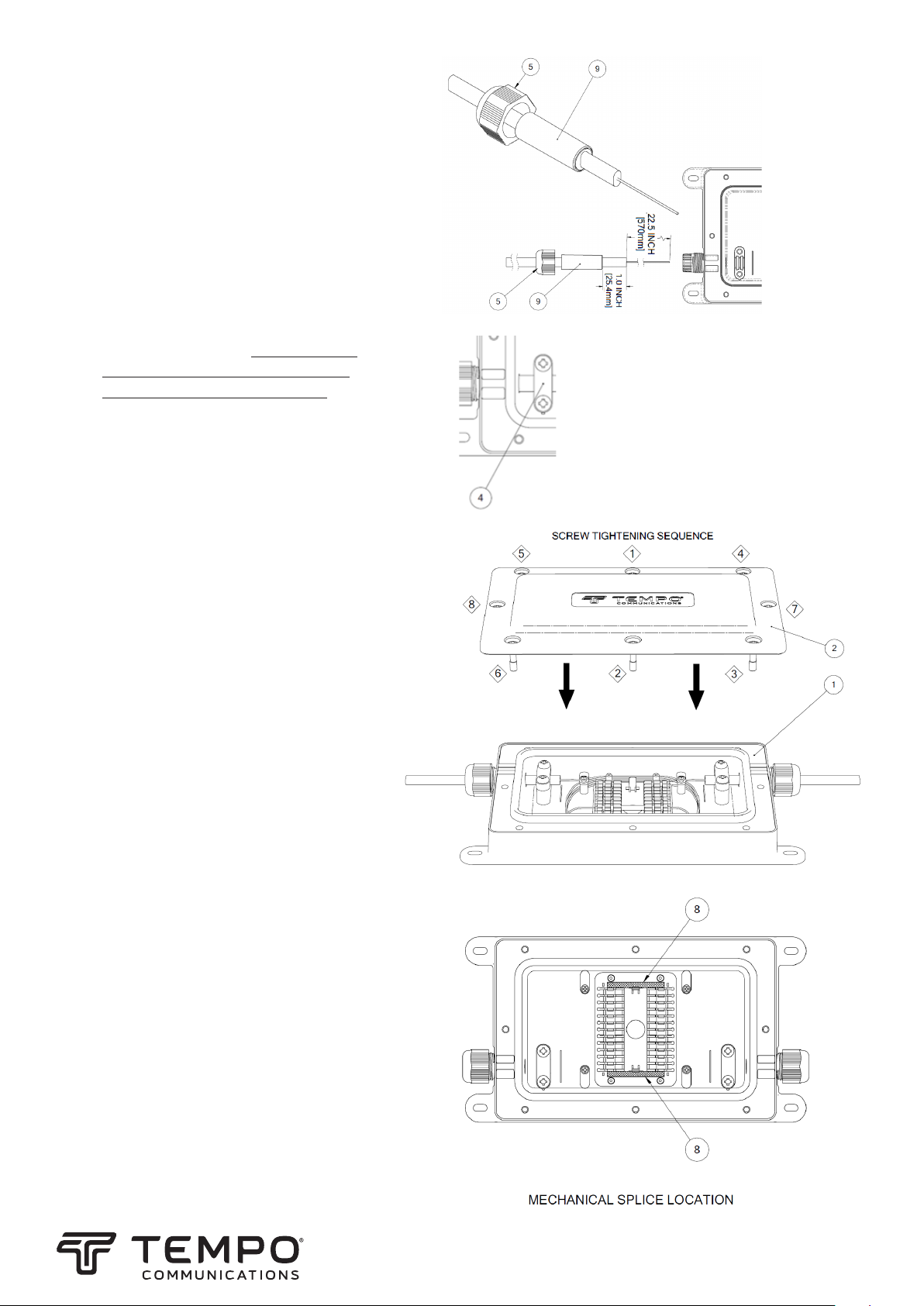
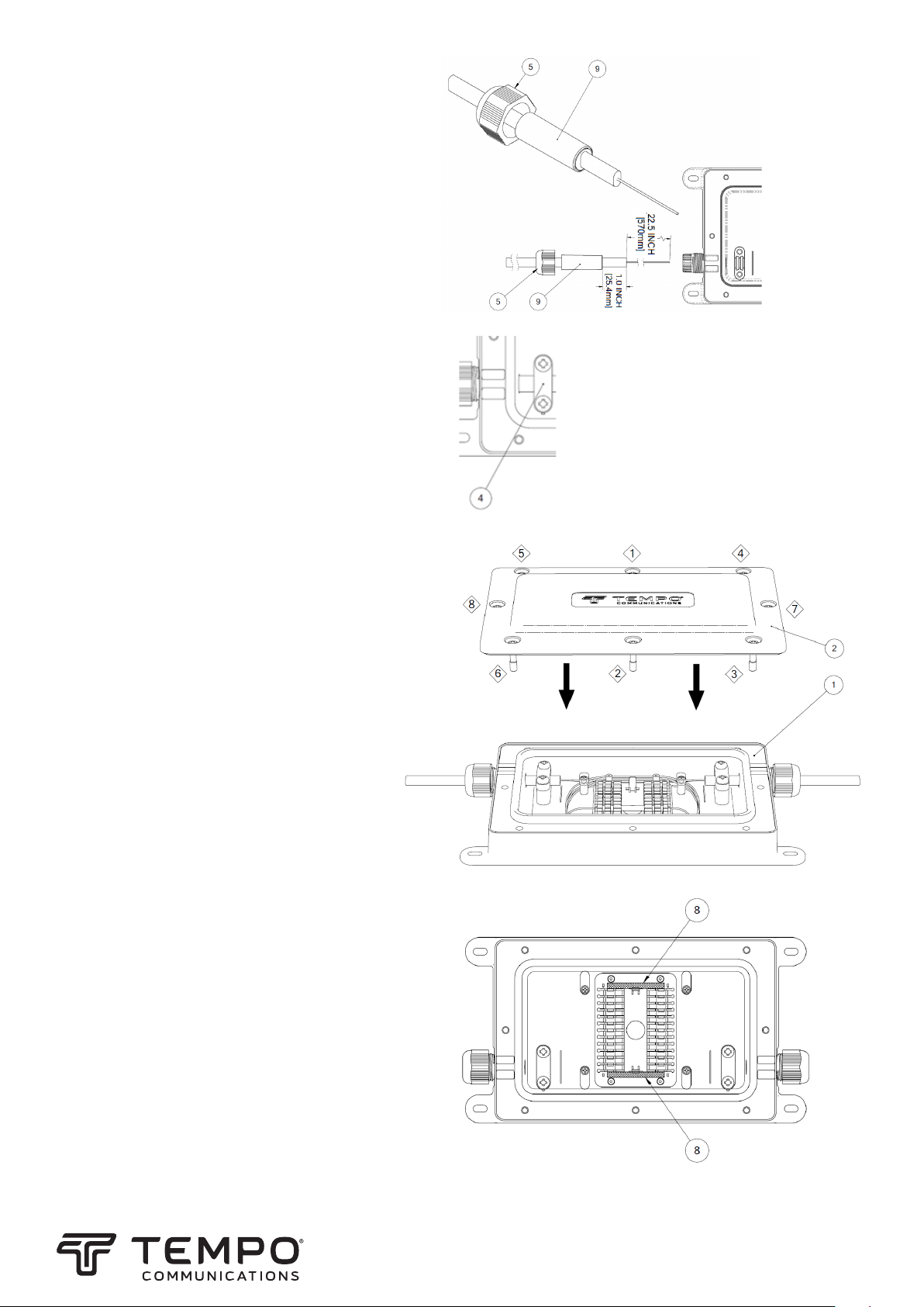
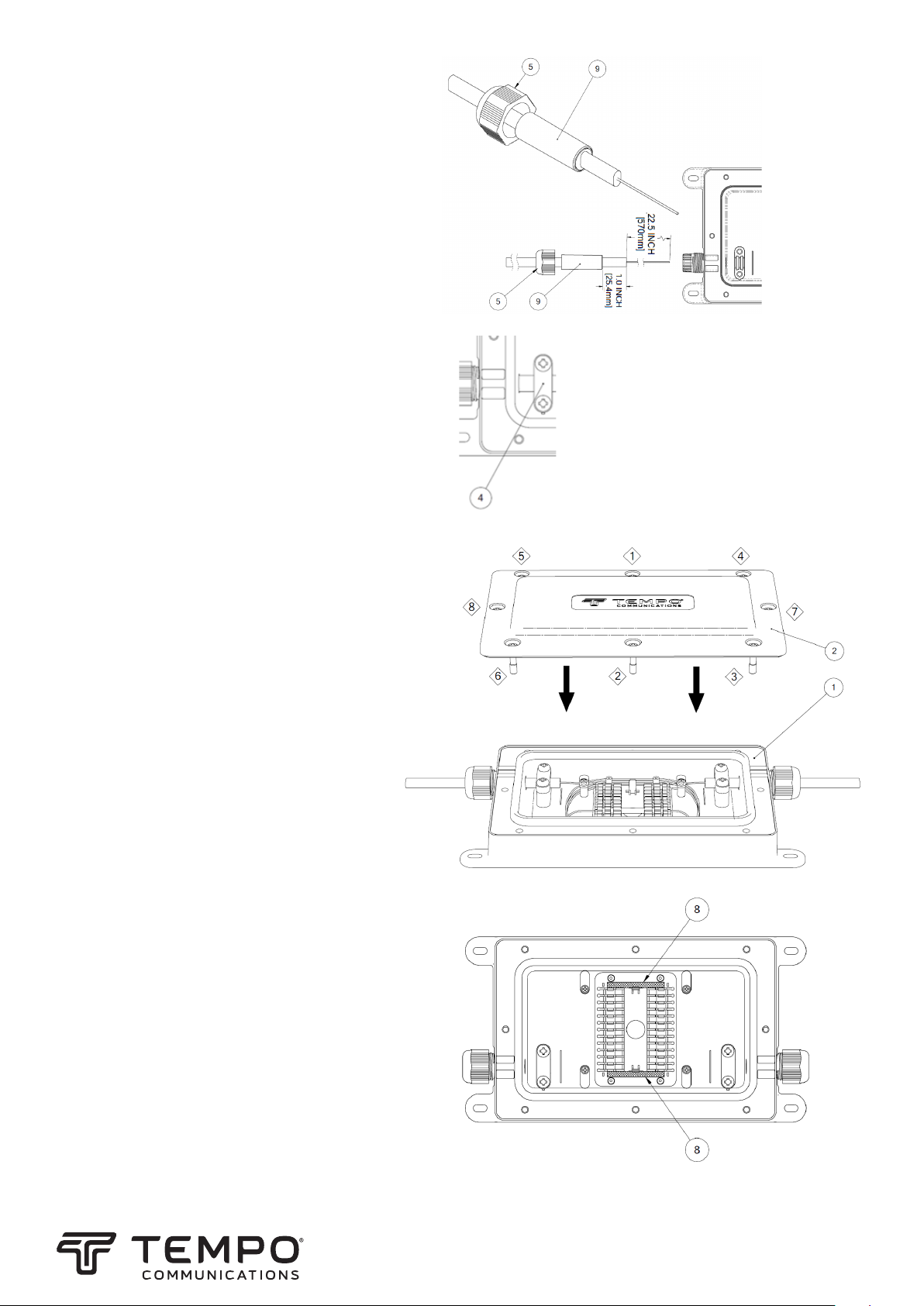
MECHANISCHE SPLEISSPOSITION
SCHRAUBENANZIEHFOLGE
1390 Aspen Way Vista, CA 92081 USA
800-642-2155
Tempo Europe Ltd. • Brecon House, William Brown Close
Cwmbran, NP44 3AB, UK • Tel: +44 1633 927 050
www.TempoCom.com
5. Bereiten Sie die beiden Fasern wie
gezeigt vor. Kabel in den An-
schluss einführen.
Table of contents
Languages:
Popular Cable Box manuals by other brands

Palmer
Palmer PLI01 manual

Minebea Intec
Minebea Intec PR 6130/68S installation manual

Keba
Keba KeContact R10 CM installation manual

Chatsworth Products
Chatsworth Products Evolution installation instructions

OBO Bettermann
OBO Bettermann GE 2V 15 B Mounting instructions

Commercial Electric
Commercial Electric 5623-WH installation guide