BEGA Gantenbrink-Leuchten KG · Postfach 31 60 · 58689 Menden · info@bega.com · www.bega.com
00.00 · Technische Änderungen vorbehalten · Technical amendments reserved · Modications techniques réservées
IP 54
!
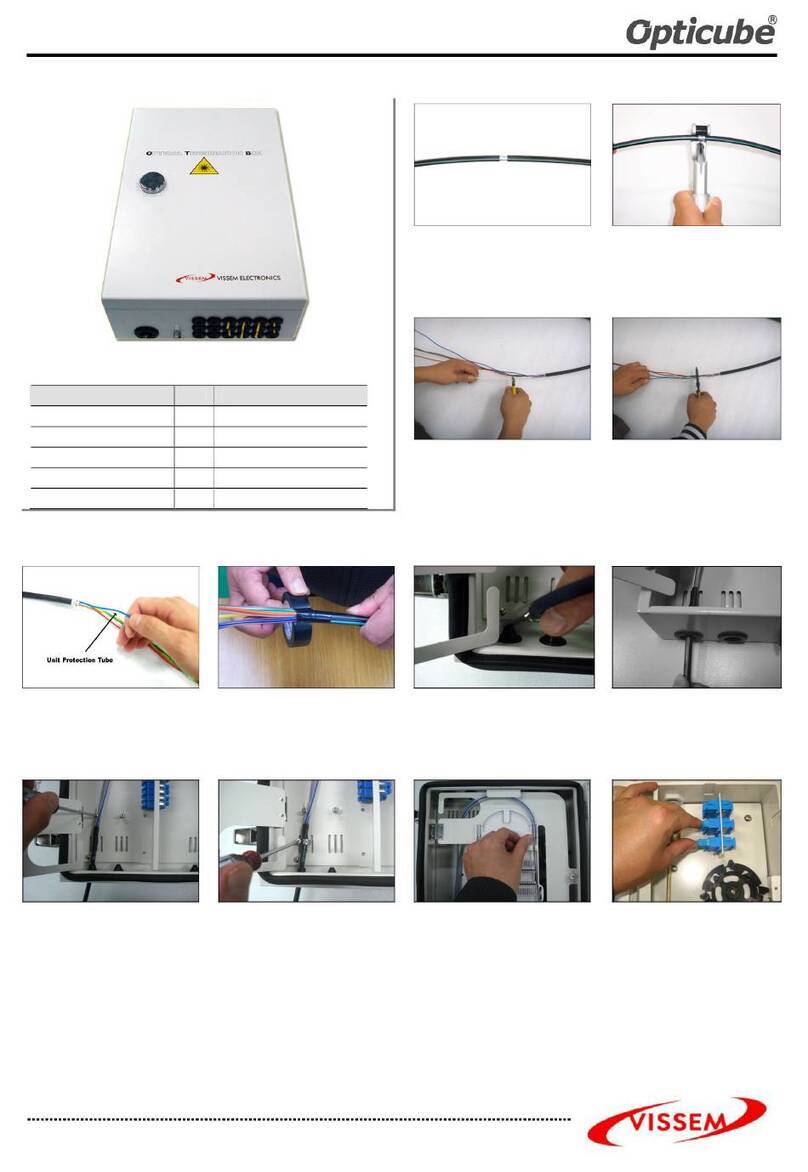
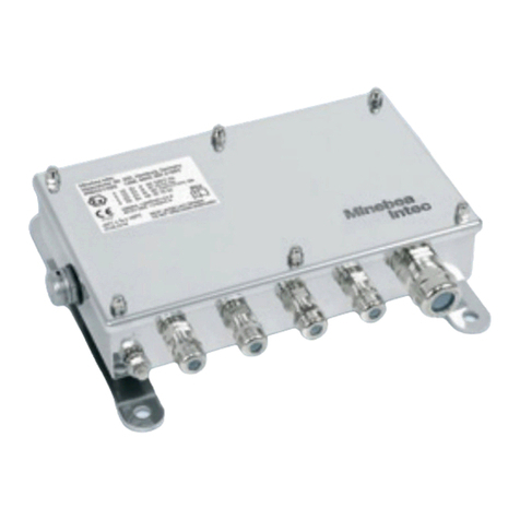
Anschlusskasten
Connection box
Boîte de connexion
70 650
2
7575 8585
275275
290290
Gebrauchsanweisung Instructions for use Fiche d’utilisation
Anwendung
Kabelübergangskasten für den Einbau in
Lichtmaste mit Mastaufsätzen für drei, vier oder
sechs Leistungsscheinwerfer.
Application
Cable connection box for installation in poles
with pole top attachments for three, four or six
high power oodlights.
Utilisation
Boîte de connexion pour l'installation dans des
mâts avec manchons d'adaptation pour trois,
quatre ou six projecteurs puissants.
Produktbeschreibung
Gehäuse besteht aus schlagzähem
Kunststoff - Polycarbonat
Brandschutz nach VDE 0304 Teil 3,
schwer entammbar und selbstverlöschend
Gehäusedeckel klar mit Schraubbefestigung
2 Befestigungslanglöcher ø 7 mm
Abstand 275 mm
für den Einbau in Maste ø > 120 mm
Türgröße ab 80 x 300 mm
2 Kabeleinführungen mit zweiteiliger
Kunststoffdichtung und integrierter
Zugentlastung für Erdkabel 5 x 4@
6 Leitungseinführungen mit Dichtnippel für
Leuchtenanschlussleitung 3 x 1,5 @
Hutschiene mit 12 Reihenklemmen:
6 Sicherung-Reihenklemmen 4@
mit Feinsicherung 5x20 mm 10A träge
1 N - Reihenklemme 4@
2 N - Reihenklemmen 2,5@
1 PE-Reihenklemme 4@
2 PE-Reihenklemmen 2,5@
Schutzklasse II 2
Schutzart IP 54
Staubgeschützt und Schutz gegen
Spritzwasser
c – Konformitätszeichen
Gewicht: 0,6 kg
Product description
Housing made of impact resistant synthetic -
polycarbonate
Fire protection according to VDE 0304 Part 3,
ame resistant and self-extinguishing
Clear housing cover with screw mounting
2 elongated xing holes ø 7 mm
Spacing 275 mm
for installation in poles ø > 120 mm
Door size from 80 x 300 mm
2 cable entries with two-part plastic gasket
and integrated strain-relief for underground
cable 5 x 4@
6 cable entries with compression nipples for
luminaire connecting cable 3 x 1,5 @
Top-hat rail with 12 serial terminals
6 fused serial terminals 4@
with micro fuse 5 x 20mm 10A slow
1 N - serial terminal 4@
2 N - serial terminals 2.5@
1 PE-serial terminal 4@
2 PE-serial terminals 2.5@
Safety class II 2
Protection class IP 54
Protection against harmful dust deposits and
splash water
c – Conformity mark
Weight: 0.6 kg
Description du produit
Boîtier fabriqué en matière plastique -
polycarbonate résistant au choc
Protection contre le feu selon VDE 0304
partie 3, très inammable et auto désamorçable
Couvercle du boîtier clair avec vissage
2 trous de xation diamètre ø 7 mm
Interdistance 275 mm
pour l'installation dans les mâts ø > 120 mm
Dimensions de la porte de 80 x 300 mm
2 entrées de câble avec joint en plastique de
deux parties et collier anti-traction intégré pour
câble réseau 5 x 4@
6 entrées de câble de raccordement avec
nipple d'étanchéité pour câble du luminaire
3 x 1,5@
Rail de montage avec 12 bornes en série:
6 bornes de sécurité en série 4@
avec fusible à l n 5 x 20 mm 10 A à action
retardée
1 N- borne en série 4@
2 N- borne en série 2,5@
1 PE- borne en série 4@
2 PE- bornes en série 2,5@
Classe de protection II 2
Degré de protection IP 54
Protection contre la poussière et les projections
d’eau
c – Sigle de conformité
Poids: 0,6 kg
Sicherheit
Für die Installation und für den Betrieb
dieses Gerätekastens sind die nationalen
Sicherheitsvorschriften zu beachten.
Der Hersteller übernimmt keine Haftung für
Schäden, die durch unsachgemäßen Einsatz
oder Montage entstehen.
Werden nachträglich Änderungen an dem
Gerätekasten vorgenommen, so gilt derjenige
als Hersteller, der diese Änderungen vornimmt.
Safety indices
The installation and operation of this control
gear box are subject to national safety
regulations.
The manufacturer is then discharged from
liability when damage is caused by improper
use or installation.
If any control gear box is subsequently
modied, the persons responsible for
the modication shall be considered as
manufacturer.
Sécurité
Pour l’installation et l’utilisation de ce coffret
à ballast, respecter les normes de sécurité
nationales.
Le fabricant décline toute responsabilité
résultant d'une mise en œuvre ou d'une
installation inappropriée du produit.
Toutes les modications apportées au coffret à
ballast se feront sous la responsabilité exclusive
de celui qui les effectue.
