Tempsens CALSYS 650 User manual
Dry Block
Temperature
Calibrator
(CALsys 650)
User’s Guide
TEMPSENS INSTRUMENT (I) PVT. LTD
A-190 ROAD #5, MIA UDAIPUR, 313003, INDIA
Phone: +91-294-3500600,
Fax: +91-294-3500631
Email: tech@tempsens.com
Web: www.tempsens.com
p

Legal Disclaimer
The information contained in this document is the property of TEMPSENS
.
TEMSPENS reserves the right to make changes to this document and to the product described herein
without notice
.
Before installing and using the product, review the latest version of the applicable
documentation, which are available from the Tempsens website at:
http://www.tempsens.com/
© 2021 Tempsens Instrument Pvt
.
Ltd
.
All Rights Reserved
.
Document Information
NAME Dry Block Temperature Calibrator (CALsys 650) User Manual
D
OCUMENT
V
ERSION
1.0
DOCUMENT CODETS.CS.001
PUBLISH DATE Wednesday, November 3, 2021
2

Table of Contents
Preface........................................................................................................................................... 5
Safety Information ..........................................................................................................................................................
5
Electrical Safety ...............................................................................................................................................................
6
Health and Safety Instructions ........................................................................................................................................
7
Cautions and Preventions ...............................................................................................................................................
8
Document Conventions...................................................................................................................................................
8
Chapter 1................................................................................................................................................
9
Introduction ................................................................................................................................... 9
About CALsys 650 ............................................................................................................................................................
9
Basic Working Model of CALsys 650 ............................................................................................................................. 10
Physical Measurements ................................................................................................................................................ 11
Wiring Diagram ............................................................................................................................................................. 11
Technical Specifications ................................................................................................................................................
12
Chapter 2
.............................................................................................................................................. 13
Setting Up CALsys 650 .................................................................................................................. 13
Installation .................................................................................................................................................................... 13
Optimal Environmental Conditions ...............................................................................................................................
13
Unpacking and Initial Inspection ................................................................................................................................... 14
Operating Instructions ..................................................................................................................................................
15
Initial Testing ................................................................................................................................................................. 15
Chapter 3
.............................................................................................................................................. 17
Operating CALsys 650 ................................................................................................................... 17
Turning On the Unit ......................................................................................................................................................
17
Heating Up the Source ..................................................................................................................................................
17
Operating Instructions ..................................................................................................................................................
18
Cooling Down the Source ............................................................................................................................................. 19
3

Dry Block Temperature Calibrator (CALsys 650)
User’s Guide
Chapter 4
..............................................................................................................................................
22
Operating Unit Controller ............................................................................................................. 22
Front Panel Layout.........................................................................................................................................................22
The Temperature Controller..........................................................................................................................................
22
Altering the Set point .................................................................................................................................................... 22
Monitoring the Controller Status ..................................................................................................................................
23
Temperature Units ........................................................................................................................................................ 23
Chapter 5
..............................................................................................................................................
24
Digital Communication ................................................................................................................. 24
Chapter 6
..............................................................................................................................................
25
Software Installation .................................................................................................................... 25
Installation ..................................................................................................................................................................... 25
Parameters on Main Screen .......................................................................................................................................... 25
Chapter 7
..............................................................................................................................................
27
Service & Maintenance ................................................................................................................. 27
Routine service .............................................................................................................................................................. 27
Replacing Controlling Sensor ......................................................................................................................................... 27
Replacing Solid State Relay ............................................................................................................................................
27
Chapter 8
..............................................................................................................................................
29
Troubleshooting CALsys 650 ......................................................................................................... 29
CALsys 650 unit does not turn on .................................................................................................................................. 29
The CALsys 650 unit is not stable .................................................................................................................................. 29
The temperature of the Calibrator Unit does not rise ..................................................................................................
29
Appendix A: Calibration Services................................................................................................... 31
In House Calibration Facility ..................................................................................................................................... 31
On-site Calibration Facility ........................................................................................................................................
32
Fixed-point Calibration Facilities...............................................................................................................................
32
Thermography Services ............................................................................................................................................
33
Appendix A: Warranty .................................................................................................................. 35
Limit of Liability.........................................................................................................................................................35
Caution in Using the Product ....................................................................................................................................
35
4
Preface
Welcome to the Dry Block Temperature Calibrator (CALsys 650) user guide
.
This guide provides
detailed information about all the product options and features, and explains how to use the product
and configure basic settings to suit your requirements.
This user manual contains information about the product and its proper use and should be kept in a
place where it will be easy to access
.
This user manual also provides safety precautions in using this
product
.
Safety Information
This topic contains important information regarding safety
.
Ignoring safety precautions may cause
serious personal injury or damage to the unit and/or its components
.
Use the equipment only as
specified in this manual
.
Otherwise, the protection provided by the instrument may be impaired.
Refer to the safety information in the Electrical Safety and Health and Safety Instructions sections or
wherever specified in this manual.
The following definitions apply to the terms “Warning”and “Caution”.
•
“Warning”identifies conditions and actions that may pose hazards to the user
.
•
“Caution”identifies conditions and actions that may damage the instrument being used.
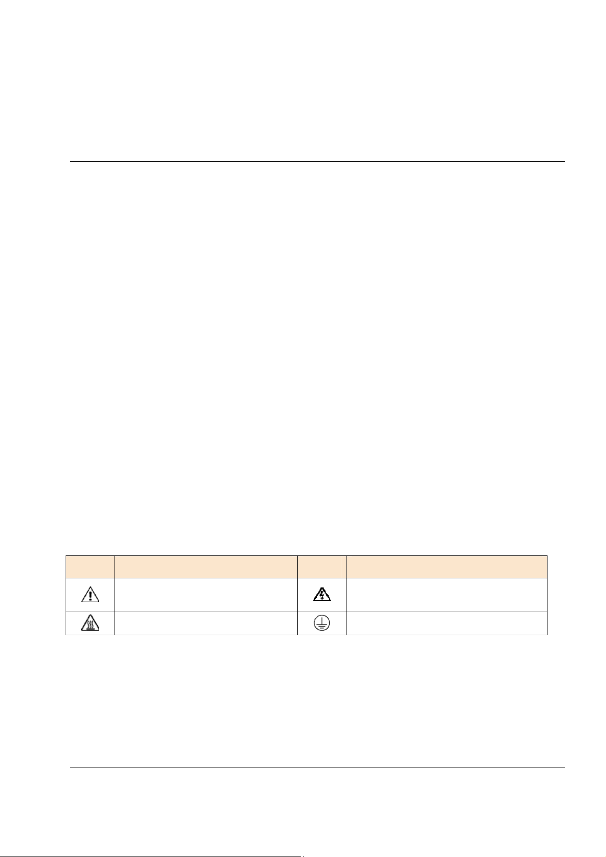
The following safety symbols may appear on CALsys 650 unit:
SYMBOL DESCRIPTION SYMBOL
Risk of Danger
.
Important information
.
See Manual
Caution, Hot Surface
Protective Earth Ground
DESCRIPTION
Hazardous voltage
.
Risk of electric shock
5

Dry Block Temperature Calibrator (CALsys 650)
User’s Guide
Electrical Safety
WARNING:
•
This equipment must be correctly grounded before use
.
Make sure the ground conductor
wire (colored green/yellow) in the main power cable is connected to a protective
earth/ground
.
If the equipment is not properly grounded, the high voltage may flow
through the equipment body (chassis)
.
SEVERE INJURY OR DEATH may result if personnel
fail to observe safety precautions.
•
Do not remove the panels from the equipment without proper safety measures to avoid
internal main power supply voltage hazard.
To avoid possible electric shock or personal injury, follow these guidelines
.
This equipment uses protective earth circuit to ensure that the conductive parts do not store electric
charges or conduct electricity if insulation fails.
•
Before connecting the equipment to the electricity supply, understand the parts of the calibrator with
the help of operating manual.
•
Use power cables only with appropriate voltage and power rating, and that are approved for usage in
your country
.
•
Replace the main power cable if the insulation is damaged, or if the insulation shows signs of wear
and tear
.
•
DO NOT put the product at the location where access to the main power is blocked.
•
DO NOT use an extension cord or adapter plug.
•
DO NOT use the product if it operates incorrectly
.
•
Make sure the power cord does not touch the hot parts of the product
.
6

Preface
Health and Safety Instructions
WARNING: BURN HAZARD - DO NOT touch the well access surface of the unit at high
temperature
To avoid possible health and safety concerns, follow these guidelines
.
•
Wear appropriate protective clothing before using the equipment
.
•
Operators of this equipment should be adequately trained in the handling of hot and cold items and
liquids
.
•
Do not use the apparatus for jobs other than those for which it was designed, that is, the calibration
of thermometers
.
•
Do not handle the apparatus when it is hot (or cold), without wearing the appropriate protective
clothing and having the necessary training
.
•
Do not drill, modify or otherwise change the shape of the apparatus
.
•
Do not use the apparatus outside its recommended temperature range
.
•
After use, do not return the apparatus to its carrying case until the unit has cooled down
.
•
There are no user serviceable parts inside
.
When required, contact Tempsens agent for repair
.
•
Ensure all materials, especially flammable materials are kept away from the hot parts of the apparatus,
to prevent fire risk
.
•
Do not use the product around explosive gas, vapor, or in damp or wet environments
.
•
Make sure that the space around the product meets minimum space requirements
.
•
DO NOT turn off the unit at temperatures higher than 100°C
.
This could create a hazardous situation
.
Select a set-point less than 100°C and allow the unit to cool before turning it off
.
•
The top sheet metal of the furnace may exhibit extreme temperatures for areas close to the well
access
.
•
Materials used in this furnace may be irritating to skin, eyes, and respiratory tract
.
Consult the
material manufacturer’s Material Safety Data Sheet (MSDS) to learn about those materials before
using
.
7
Dry Block Temperature Calibrator (CALsys 650)
User’s Guide
Cautions and Preventions
To avoid possible damage to the instrument, follow these guidelines:
•
Before working inside the equipment, turn the power off and disconnect the power cord.
•
DO NOT turn the unit upside down with the inserts in place; the inserts will fall out of the unit
.
•
Use of this instrument at HIGH TEMPERATURES for extended periods of time requires caution
.
•
Completely unattended high temperature operation is not recommended for safety reasons
.
•
DO NOT plug the unit into 230 V if the heater switches and fuse holder reads 115 V
.
This action will
cause the fuses to blow and may damage the instrument.
•
Components and heater lifetime can be shortened by continuous high temperature operation.
•
DO NOT use fluids to clean out the well.
•
Never introduce foreign material into the probe hole of the insert
.
Fluids and other materials can leak
into the calibrator causing damage
.
•
DO NOT drop or force the probe stems into the well
.
This type of action can cause a shock to the
sensor and affect the calibration.
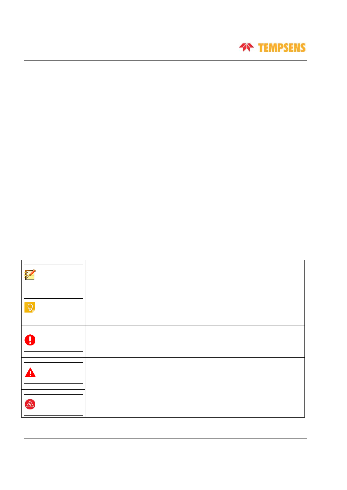
Document Conventions
The documentation uses the following conventions.
Configuration notes
Note:
Recommendations or suggestions
Tip:
Information regarding required or default configuration settings and product limitations
Important:
Critical actions and configuration options
WARNING:
WARNING:
8

Chapter 1
Introduction
About CALsys 650
CALsys 650 has been designed to provide stable and accurate temperature to enable professionals to
calibrate temperature sensing devices by comparison method
.
It is designed to be rugged and easily
maintained
.
This model provides an isothermal enclosure (Metal block) in which the
thermocouple/RTD can be calibrated against the temperature of the calibrator.
For traceable calibration, a master calibration sensor should be placed into the metal block alongside
the unit under calibration
.
This method is widely accepted because the calibrator provides very stable
temperature nearing to its controlled point, that is, the Master Thermocouple/RTD
.
The controlled
point is calibrated by independent laboratory in compliance to the national standards, and compares
the sensor under calibration.
The CALsys models are part of wide range of portable calibrators designed and made by Tempsens.
Contact Tempsens to learn more about other products by Tempsens
.
9

Dry Block Temperature Calibrator (CALsys 650)
User’s Guide
Basic Working Model of CALsys 650
The purpose of the CALsys 650 is to provide an isothermal enclosure for calibration purpose
.
The
heater block contains a heater and a control sensor that are used by the temperature controller to
sense the block temperature
.
To obtain and maintain a required temperature the controller varies
the power to the heater via solid-state relay
.
There is one electricity driven fan which is situated
under the heating chamber for cooling the heater
.
The fan runs continuously.
The calibrator controller uses a precision N-type thermocouple as a controlling sensor and controls
the well temperature with MI heater
.
The CALsys 650 dry block calibrator was designed for portability,
moderate cost and ease of operation
.
With proper use, the instrument should provide continued
accurate calibration of temperature sensors and devices
.
Important:
Before using the equipment, read the safety guidelines and operating procedures of the calibrator as
described in the Preface of this user manual.
The basic working model for CALsys 650 is as follows:
10
Dry Block Temperature Calibrator (CALsys 650)
User’s Guide
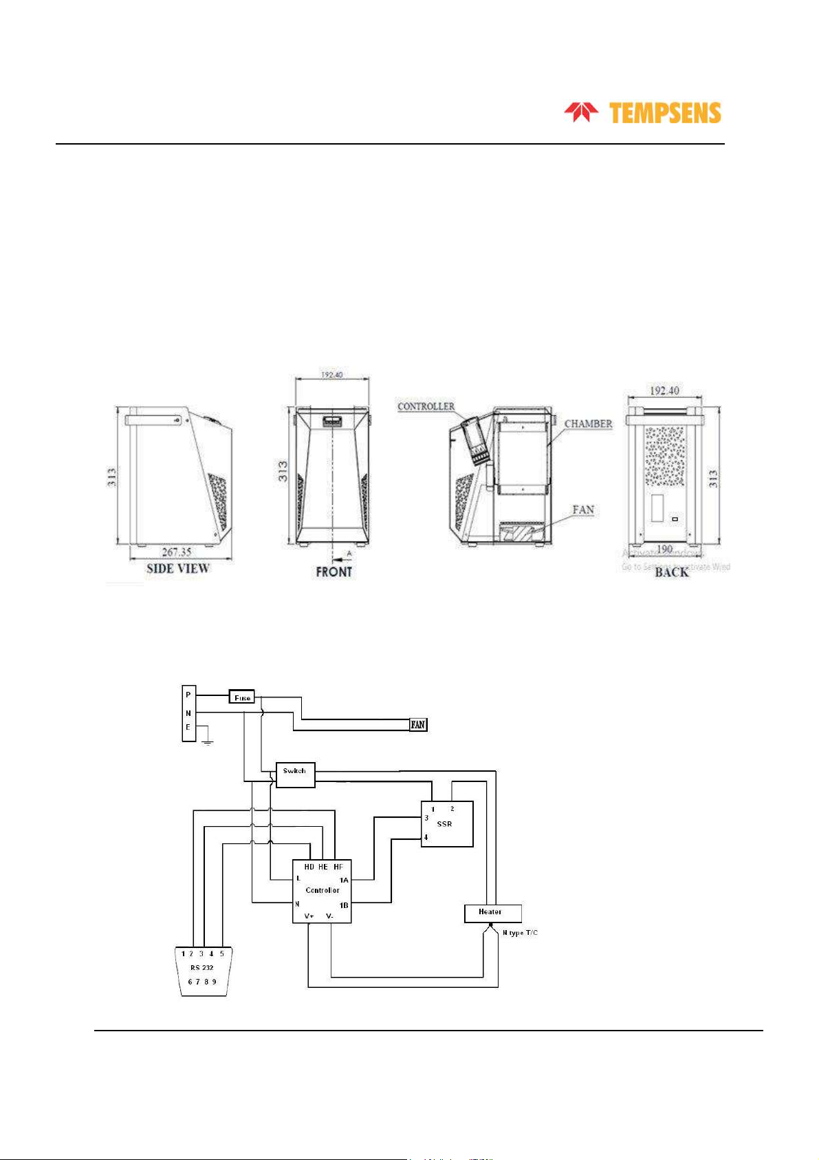
Physical Measurements
CALsys 650 has the following physical measurements:
•
Height: 325mm
•
Width: 192mm
•
Depth: 267mm
Wiring Diagram
Refer to following figure for CALsys 650 wiring diagram.
11
Dry Block Temperature Calibrator (CALsys 650)
User’s Guide
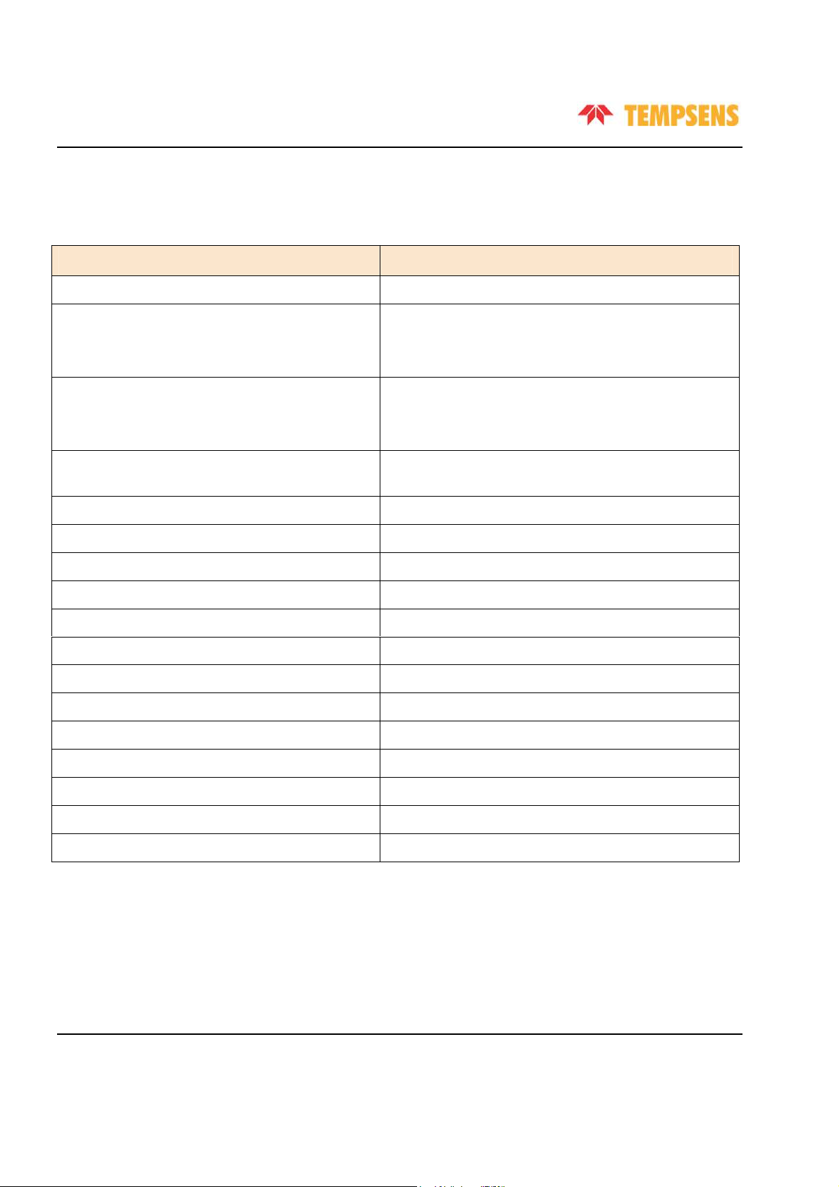
Technical Specifications
CALsys 650 has the following technical specifications:
PARAMETER SPECIFICATION
Temperature range
50°C to 650°C
Stability
±0.01°C at 50°C
±0.02°C at 350°C
±0.05°C at 650°C
Radial uniformity
±0.04°C at 50°C
±0.07°C at 350°C
±0.09°C at 650°C
Loading effect (with a 6.35mm reference probe and
0.04°C
three 6.35mm probes)
Insert OD dimensions
32mm
Immersion depth
120mm
Cooling time
80 minutes (650°C to 100°C)
Heating time
20 minutes
Resolution
0.1°C
Display
LCD, with °C or °F user-selectable
Power requirements
230VAC, 1KW (50Hz)
Calibration
Accredited calibration certificate provided
Environmental operating conditions
0°C to 40°C, 0% to 90% RH (non-condensing)
Specifications valid in environmental conditions
13°C - 33°C
PC Interface
RS-232/ USB
Size (H x W x D)
325 x 192 x 267mm
Weight 10kg
12

Chapter 2
Setting Up CALsys 650
Installation
Place the black body on a flat surface with at least 10 inches of free space around the instrument
.
Overhead clearance is required
.
DO NOT Place this unit under a cabinet or structure
.
Plug the power cord into a grounded main
outlet located on the controlling unit rear panel
.
Observe that the nominal voltage corresponds to
that indicated in the technical specifications in Technical Specifications
in
Chapter 1 of this user’s
guide
.
Optimal Environmental Conditions
Although the instrument has been designed for optimum durability and trouble-free operation, it
must be handled with care
.
The instrument should not be operated in an excessively dusty or dirty
environment
.
Refer to Chapter 7
,
Service & Maintenance in this user’s manual for routine service and
cleaning recommendations.
The instrument operates safely under the following conditions:
•
Temperature range: 5 - 50°C (41 - 122°F)
•
Ambient relative humidity: 15 - 50%
•
Pressure: 75kPa - 106kPa
•
Main voltage supply within ± 10% of nominal voltage range
•
Vibrations in the calibration environment should be minimized
•
Altitude less than 2000 meters
13

Dry Block Temperature Calibrator (CALsys 650)
User’s Guide
Unpacking and Initial Inspection
CALsys 650 is packed in custom-designed packaging to send out your unit. Unpack the furnace
carefully. Inspect the unit after unpacking for any signs of damage, and confirm that your delivery is
in accordance with the packing note. If you find any damage to the unit or an item is missing, notify
Tempsens immediately.
The following accessories are included in the package:
•
CALsys 650
•
Power cord
•
USB Cable
•
External Reference Sensor (K-type Thermocouple (TC))
•
Brass block
•
Tool for Insert
•
Manual
•
Certificates
•
`Ceramic Wool
14

Dry Block Temperature Calibrator (CALsys 650)
User’s Guide
Operating Instructions
1. Open the carrying case carefully and takeout the operating manual from the box and read carefully.
2. Take out the Temperature Calibrator unit carefully and keep it at suitable place.
3. Connect the power cable to the rear power entry and the power plug to the main power outlet
.
4. Turn the switch on, and observe the display on the controller
.
The display shows that the bath is ready
for use
.
5. Keep the switch in the ON position
.
6. Ensure the metal INSERT is properly inserted in the bath
.
7. Keep the fan in ON position.
8. If the fan is running and temperature of the furnace is rising, the bath is in healthy condition
.
Note:
•
The unit must be correctly connected to the electricity supply
.
•
The unit must be correctly grounded
.
•
The unit’s ON/OFF switch is located on the power inlet. DO NOT switch OFF the unit when it is hot.
Keep the unit running until cooled
.
Initial Testing
This unit is fully tested before dispatching
.
However, verify its operation as follows:
1. After connecting the CALsys 650 to the electricity supply, the temperature controller display
should show the temperature of the chamber, and the last set-point value
.
The fan on the bottom
should be heard running.
2. Change the set-point to 100°C and observe that the block temperature rises and settles to this
value
.
3. If the unit performs as expected, the unit can now be used for calibration
.
If any problems or faults arise during the test, contact Tempsens immediately for help and advice.
15

Dry Block Temperature Calibrator (CALsys 650)
User’s Guide
This page is intentionally left blank
.
16

Chapter 3
Operating CALsys 650
Turning On the Unit
1. Before plugging the unit to main power outlet, ensure that the voltage, frequency and current
from the main power outlet are within the recommended rages (typically: 230 VAC±10, 50/60 Hz)
.
2. Plug the black main power cord into main outlet
.
3. Turn the controller on using the switch located on the controlling section, and set the
temperature value in the controller
.
The Calibrator will turn on and begin to heat the previously
programmed temperature set-point
.
Heating Up the Source
Press “UP
”or “
DOWN”key of controller to change the set-point value
.
The controller switches the
calibrator heater to ON or OFF to raise or lower the temperature
.
The displayed temperature will
gradually change until it reaches the set-point temperature
.
The Calibrator may require 15 to 20 minutes to reach the set-point depending on the span
.
The unit
takes 15 to 20 minutes more to stabilize the bath temperature within ± 0.1°C of the set-point
.
17

Dry Block Temperature Calibrator (CALsys 650)
User’s Guide
Note:
•
All other controller parameters are set to default, and are locked
.
It is recommended not to change
these parameters
.
Important
:
•
When the source is operated at any temperature above ambient temperature, the front face and plate
become hot
.
•
Always put the fan in "ON" condition and do not switch off the main power supply directly.
Before
tuning the unit off, set the controller to 0
°
C, and then wait until the temperature drops below 100
°
C
.
Operating Instructions
1. Connect the CALsys 650 to a suitable power supply
.
2. Place the metal insert in the bath
.
3. Place the sensors for calibration and master sensor into a suitable insert hole.
4. Set the controller to the required temperature
.
5. If test and master sensor are thermocouple, then always use compensating cable (for each type
such as J, K, T, E, N, R, S, B) for interconnection between sensor and Digital Multimeter (DMM)
.
6. Keep reference junction at 0°C
.
If keeping at 0°C is not possible, then add millivolt (mV) of room
(ambient) temperature with sensors output (mV) to compensate the ambient temperature.
7. When controller temperature becomes stable, record the reading from DMM with at least 41/2
digit precision, which should be calibrated for the measuring range (mV & ohms measurements)
.
8. Find out the error by comparison method.
9. Reset the controller and/or repeat the calibration for another calibration point or for another
sensor.
10. When the calibration is completed, reset the controller to 0°C
.
Before moving CALsys 650
to new
location the unit
must be cooled to below 100°C.
18

Dry Block Temperature Calibrator (CALsys 650)
User’s Guide
Note:
•
Metal Insert should be of required hole size so that the hole size is suitable for sensor under calibration
.
•
Always use a master sensor (master RTD/TC) for comparison calibration method
.
•
Place the metal insert first in all sensors, and then set the controller at desired set point.
•
Check that all sensors (test and master) are immersed at same depth in insert (metal block)
.
•
If sensors are not immersed at same depth than there will be an error in temperature reading.
•
Always use a metal block calibrator (insert)
.
Metal block calibrator heat transfer characteristics should
match with those in the normal measuring situations.
•
The temperature sensors should be long enough to immerse completely in the calibration bath
.
Errors
due to stem conduction can be ignored
.
•
Do not change the set temperature value too often
.
For example, you set the temperate initially at
100
°
C, and when it reaches at 80
°
C, you change the temperature to 150
°
C. Or, you set the
temperature initially at 150
°
C, and when it reaches close to 150
°
C, you change the temperature to
100°C
.
Doing so may affect unit’s performance
.
•
Plan the calibration point by gradually increasing temperature, then set the controller accordingly
. This
method will save the time.
•
Take the reading of sensors (master and test) at stable temperature with the help of digital multi-
meter, or by using Tempsens’ TEMPMET 08 or TEMPMET 09 for reading RTD or TC sensor.
Cooling Down the Source
•
Before transporting the metal block, ensure that the temperature of bath has cooled sufficiently.
19

Dry Block Temperature Calibrator (CALsys 650)
User’s Guide
•
If you require metal block to cool quickly, set the temperature to the room temperature (ambient
temperature)
.
•
Always cool the heated instrument to ambient temperature before disconnecting it from the
mains, switching it OFF, or removing the temperature sensor or test item.
•
Always keep the heated instrument supervised and under observation until it cools down
sufficiently
.
20
Other manuals for CALSYS 650
1
Table of contents
Other Tempsens Test Equipment manuals


