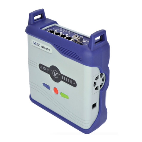
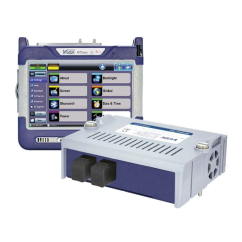
VeEX MTX150 Series User manual

MTX150x User Manual
Multi-Service Installation & Maintenance Test Set
P/N D07-00-148P Rev. B00

Please direct all questions to your local VeEX® Sales Office, Representative, or Distributor. Or, contact VeEX tech-
nical support at www.veexinc.com.
No part of this user manual may be reproduced, translated into a foreign language, or be transmitted electronically
without prior agreement and written consent of VeEX Incorporated as governed by International copyright laws.
Information contained in this manual is provided "as is" and is subject to change without notice. Trademarks of
VeEX Incorporated have been identified where applicable, however the absence of such identification does not
affect the legal status of any trademark.
Copyright ©2022 VeEX Incorporated. All rights reserved.

Table of Contents
General Information 12
Customer Support 12
Product Technical Support Contact Information 12
Warranty 13
Patent Information 13
Documentation Conventions 13
Safety Information 14
Lithium-Polymer Battery Precautions 14
General Safety Guidelines 14
Lithium Polymer Battery Handling & Storage Advice 15
Optical Connectors 16
Safe Module Handling 16
Electrical Connectors 16
ESD: Electrostatic Discharge Sensitive Equipment 16
Introduction 18
Product Specifications 18
Basic Operation 19
MTX150X Chassis Overview 19
MTX150X Connector Panel 19
Hard Buttons and Interfaces 21
Special Functions 23
Touch-Screen Display 24
Platform Screen Icons 25
LEDs 25
Home Menu and Screen Icons 27
Mode/Port Selection 27
Ethernet 29
Setup 29
Port Setup 29
100/1000Base-X and 100/1000Base-T Port 30
Status 31
Table of
Contents © VeEX Inc. All Rights Reserved. 3

10 GE Port 32
Measurement Settings 32
MX Discover and Control Settings 34
Using MX Discover 34
Loop Control 35
IP 36
IP Connection 36
Setup 37
Point-to-Point Protocol over Ethernet(PPoE) 37
IPv4 or IPV6 38
Status 39
Trace Route 39
Trace Route Setup 40
Results 41
ARP Wiz 41
ARP Setup 41
ARP Result 42
Ping 42
Ping Testing 42
Ping Setup 43
Ping Results 43
BERT 44
BERT Setup 44
Overview 45
Header Settings 46
Traffic 56
Error Injection 59
Starting/Stopping a BERT 60
BERT Results 61
Summary 61
Errors 62
Events 63
Traffic Settings 63
4 © VeEX Inc. All Rights Reserved. Table of
Contents

Rates 64
Delay 65
Alarms 66
Signal 66
RFC 2544 Conformance Testing 68
Overview 68
Setup - Standard Mode 69
Header Settings 69
RFC 2544 Setup 69
Frame Settings 70
Threshold Settings 71
Throughput, Latency, Frame Loss, and Burst Settings 72
Starting/Stopping a RFC 2544 Measurement 77
Results - Standard Mode 78
Saving RFC 2544 Results 87
Advanced SLA Mode 89
Background Results - Advanced SLA Mode 93
Peer-to-Peer and Asymmetric Testing 94
Asymmetric Testing Setup 95
Unit as Controller Setup Process 95
Unit as Responder Setup Process 97
RFC 2544 Local and Remote Test Setup 98
Test Results 99
Viewing and Managing Files 100
Enabling To USB and From USB Functions 101
Downloading Files To USB 101
V-SAM 101
Test Methodology 102
Phase 1: Service Configuration Test 103
Phase 2: Service Performance Test 104
V-SAM Setup 104
Header Settings 106
Service Attributes 109
Table of
Contents © VeEX Inc. All Rights Reserved. 5

Results 120
Throughput Testing (Multiple Streams) 124
Overview 124
Setup 124
Ping Testing 125
Ping Setup 126
Ping Results 126
ARP Setup 127
ARP Result 128
General Throughput Settings (Global Configuration) 129
MX Discover and Control Settings 132
Loop Control 133
Per Stream Configurations 134
Summary 136
Starting/Stopping a Throughput (Multiple Streams) Test 136
Throughput Results 137
Viewing Throughput (Multiple Streams) Test Results 137
Global/Aggregate Results 137
Per Stream Results 144
Saving Throughput (Multiple Streams) Results 149
Viewing and Managing Files 150
Enabling To USB and From USB Functions 151
Downloading Files To USB 151
Layer 4+ Applications 152
TCP Protocol and Overview 152
Layer 4+ Applications Configuration 157
V-Perf 158
Server/Client - Unidirectional Configuration and Results 159
Bi-Directional Configuration and Results (VeEX Enhanced Testing Methodology Implementation)164
V-TEST 165
V-FTP 170
SyncE 171
SyncE Setup 172
6 © VeEX Inc. All Rights Reserved. Table of
Contents

Port (Test Port selection) 172
Port Page 2 - Mode Selection 172
Status 174
SyncE Wander Measurements (Slave Mode only, Optional) 175
Recovered Clock Wander Measurements 176
Wander Measurements Setup 176
Results 177
Built-in MTIE & TDEV Analysis (Optional) 178
TIE Results 179
MTIE & TDEV Pass/Fail Analysis 180
VeEX MTIE/TDEV Wander Analysis PC Software 181
TIE Measurement Results 182
MTIE & TDEV Analysis 182
MTIE & TDEV Analysis Report in PDF 183
ESMC SSM 184
Setup 187
Results 187
Monitor 188
Capture 188
Phy Mode 189
Net Wiz 190
Cable Test 191
Discovery Setup 192
Discovery Results 192
Autoscripting 194
Setup 195
Results 195
L2 Control Protocol Transparency Test (L2CP) 196
Setup 196
Fiber Channel 202
Fiber Channel Applications 202
Fiber Channel over IP 202
Fiber Channel over SDH/SONET 202
Table of
Contents © VeEX Inc. All Rights Reserved. 7

Key Test Applications 203
Setup 204
Understanding the Basic Test Channel Frame Structure 206
Frame Delimiters 206
Ordered Set 206
Start of Frame (SOF) and End of Frame (EOF) Delimiter setup 207
Header Setup (FC-2 only) 212
Test Applications 216
Port Configuration 217
BERT/Throughput 220
Overview 220
Fiber Channel Layers 221
Fiber Channel layers and functionality 222
Setup 223
Traffic Generation and Error Injection 223
Starting Measurements 226
Results 226
Summary 226
Errors 227
Alarms 229
Service Disruption Test (SDT)(Throughput only) 230
Events 230
Traffic Distribution Overview 231
Traffic DistributionDetails - Frames 232
Traffic Distribution - Traffic Type 233
Frame Size Distribution 234
Delay 234
Signal 236
RFC 2544 237
Loopback 238
Common Functions 240
Utilities Overview 241
8 © VeEX Inc. All Rights Reserved. Table of
Contents

About 241
Backlight 241
On Battery Power 241
Brightness 242
Touch Screen Calibration 242
Standby Mode 243
Global Settings 244
Bluetooth 245
Bluetooth Setup 247
Bluetooth 247
WiFi Wiz 249
WiFi Procedure 250
AP List 250
Connect 251
Status 251
AP Mode 253
Date and Time 253
LAN (USB OTG Adapter) 254
Setup 255
IP Connection Status 256
Ping 256
Trace Route 258
Power 260
Remote Access 260
ReVeal Software 261
Remote Access with VNC Server/Viewer: 261
EZ Remote 262
Initiate an EZ Remote Session from the Test Set 263
Connect to the Remote Test Set from a Computer, Tablet or Phone 265
Save Test Results 268
Access Remote Test Result Files 268
Screen Shots 270
File Management 270
Table of
Contents © VeEX Inc. All Rights Reserved. 9

Working with Saved Results, Profiles, Images 270
Viewing and Managing Files 271
Enabling To USB and From USB Functions 272
Downloading Files To USB 272
USB Memory Browser 272
Manage SD Card 273
Fiber Tools Overview 274
Fiber Scope 274
OTDR View 275
OPM 275
Browser 275
OTDR Viewer 276
Fiber Scope 276
DI-1000 Digital Fiber Inspection Microscope 277
DI-1000MPO Digital Fiber Inspection Microscope for Single and Multi-Fiber Connectors 278
DI-3000 Auto-Focus Digital Fiber Inspection Microscope 281
Connecting the Fiberscope 282
Fiberscope Setup 285
Capture Images (View) 288
Results/Reports 291
Fiberizer Cloud 292
Optical Power Meter (OPM) 294
Connecting an External OLTS Device 294
Using OLS (Optical Light Source) Menu 294
Setup and Measurements 295
Results 296
Web Browser 297
Help 298
Software Update Process 299
Certifications and Declarations 301
What is CE? 301
RoHS ComplianceVeEX QUALITY AND ENVIRONMENTAL POLICY 301
About VeEX 303
10 © VeEX Inc. All Rights Reserved. Table of
Contents

General Information
This user manual is suitable for novice, intermediate, and experienced users and is intended to help use the
features and capabilities of VeEX Inc. products successfully. It is assumed that the user has basic computer
experience and skills, and is familiar with telecommunication and other concepts related to VeEX Inc. product
usage, terminology, and safety.
Every effort was made to ensure that the information contained in this user manual is accurate. Information is
subject to change without notice and we accept no responsibility for any errors or omissions. In case of dis-
crepancy, the web version takes precedence over any printed literature. The content in this manual may vary
from the software version installed in the unit.For condition of use and permission to use these materials for
publication in other than the English language, contact VeEX Inc.
© CopyrightVeEX Inc. All rights reserved. VeEX, Sunrise Telecom, Digital Lightwave, Air Expert, CaLan,
FaultScout, Fiberizer, MPA, MTT, RXT, VeGrade, VeriPHY,andVeSion, among others,are trademarks or
registered trademarks of VeEX Inc. and/or its affiliates in the USA andother countries. All trademarks or
registered trademarks are the property of their respective companies. No part of this document may be repro-
duced or transmitted electronically or otherwise without written permission from VeEX Inc.
This manual describes software and/or a device that uses software either developed by VeEX Inc. or licensed
by VeEX Inc.from third parties.The software is confidential and proprietary of VeEX Inc. The software is pro-
tected by copyright and contains trade secrets of VeEX Inc. or VeEX's licensors.The purchaser of this device
and/or software, downloaded or embedded, agrees that it has received a license solely to use the software as
embedded in the device and/or provided by VeEX Inc., and to use it solely as intended and described in this
manual. The purchaser is prohibited from copying, reverse engineering, decompiling, or disassembling the
software.
Customer Support
For more technical resources, visit www.veexinc.com
For assistance or questions related to the use of this product, call or e-mail our customer care department for
customer support. Before contacting our customer care department, have the product model, serial number,
and software version ready. Please locate the serial number on the back of the chassis. Please provide this
number when contacting VeEX Inc. customer care.
Support hours may vary depending on the product.
Product Technical Support Contact Information
Hours: Support is generally available 8:00 AM to 8:00 PM, Eastern Standard Time, Monday to Friday.
Phone: +1 510 651 0500
E-mail: [email protected]
12 © VeEX Inc. All Rights Reserved. Table of
Contents

13 © VeEX Inc. All Rights Reserved. General Information
Warranty
For warranty information on VeEX Inc. products, go to www.veexinc.com.
To activate the warranty, please register your production at www.veexinc.com/Support/ProductRegistration.
Patent Information
VeEX Inc. product hardware and software may be protected by one or more patents on file with the United
States Patent Office.
Documentation Conventions
Icons used in this manual:
Marks a helpful tip (action or method), which can save time and improve usability of the
product.
Provides important information needed to use this product and avoid missteps.
Cautions against and action or inactivity, which can hinder productivity.
Strongly warns against a condition, an action, or inactivity which can lead to a health
hazard, injury, equipment damage, data loss, and/or financial losses.
Stop and read before continuing.

Safety Information © VeEX Inc. All Rights Reserved. 14
Safety Information
Safety precautions should be observed during all phases of operation of this instrument. The instrument has
been designed to ensure safe operation; however, please observe all safety markings and instructions. Do not
operate the instrument in the presence of flammable gases or fumes or any other combustible environment.
VeEX Inc. assumes no liability for the customer's failure to comply with safety precautions and requirements.
Lithium-Polymer Battery Precautions
LiPO batteries are intended to be used with compatible VeEX products only. Any damaged caused by misuse
or modifications will void the warranty and can cause serious injury.
The test set unit's battery pack is also fitted with a safety connector to prevent accidental short circuits and
reverse polarity.
General Safety Guidelines
lNEVER use any other charger (e.g., for NiCd, NiMH, or Li-ion) other than the one supplied by VeEX
to charge the Li-Po batteries in this product. Only use chargers designed for Lithium Polymer (Li-Po)
batteries.
lNEVER attempt to service or remove the battery from this product.
lNEVER let the battery’s positive and negative leads to touch. This can cause the battery to short and
lead to a FIRE. If for any reason you need to cut the terminal wires, it will be necessary to cut each
wire SEPARATELY, to make sure the wires do NOT touch each other.

15 © VeEX Inc. All Rights Reserved. Safety Information
lNEVER charge a swollen or ballooned battery (even if swollen upon purchase). Continuing to charge
a battery that has begun to swell will result in a fire. Follow these steps:
lSTOP the charging process and disconnect battery immediately
lDisconnect battery from the device immediately.
lPlace it in an open non-flammable area.
lWatch it for approx. 30 minutes from a safe distance.
lFollow proper procedure to dispose of battery, according to local laws or ordinaces.
lAfter impact, drop or high shock, check the product for dents, punctures or cracks on its back.
Do not leave the product unattended while charging, after a high impact event.
Lithium Polymer Battery Handling & Storage Advice
lKeep LiPo battery packs out of reach of children or pets.
lALWAYS store equipment containing Li-Po batteries in cool, dry places between 40-80° F (below 0C
or above 50C).
lDo not put battery packs in pockets or bags where they can short circuit.
lDo not store or transport batteries where they can come into contact with sharp or metallic objects.
lThe speed at which a LiPo battery ages during storage is based on both storage temperature and
state of charge. For optimum battery life always store your LiPo’s partially charged at room tem-
perature. This will maintain their performance levels over time and there’s no need to cycle them
unless stored for periods longer than 3-6 months.
lNever store a RC LiPo in a hot car fully charged for an extended period of time, this will cause dam-
age.
lWhen storing batteries for extended periods, store at a half charged state.

Safety Information © VeEX Inc. All Rights Reserved. 16
Optical Connectors
The test sets display a laser warning icon when the laser source is active to alert the user about a potentially
dangerous situation. It is recommended to:
1. Deactivate the laser before connecting or disconnecting optical cables or patchcords.
2. Never look directly into an optical patchcord or an optical connector interface (SFP+) while the laser
is enabled. Even though optical transceivers are typically fitted with Class 1 lasers, which are con-
sidered eye safe, optical radiation for an extended period can cause irreparable damage to the eyes.
3. Never use a fiber microscope to check the optical connectors when the laser source is active.
Safe Module Handling
While replacing test modules, all work on the open panel must be performed only by suitably qualified per-
sonnel who is familiar with the dangers both to people and to the instrument itself.
Modules are not hot swappable. The platform must be turned off and unplugged from VAC mains when remov-
ing or inserting test modules.
For safety and EMC (Electromagnetic Compatibility), empty module slots must be properly covered with blank
panel covers.
Prevent foreign objects from entering the chassis, before, during and after module exchange or re-con-
figuration process. They could create short circuits or damage internal fans.
Always store test modules by themselves in individual ESD protected packaging (with no loose elements, like
screws or tools).
Electrical Connectors
Telephone lines may carry dangerous voltage. Always connect the electrical test ports to known test interfaces
which carry low level signals.
ESD: Electrostatic Discharge Sensitive Equipment
Test modules could be affected by electrostatic discharge. To minimize the risk of damage
when replacing or handling test modules, make sure to follow proper ESD procedures and
dissipate any electrostatic charge from your body and tools and the use proper grounding
gear.
lPerform all work at a workplace that is protected against electrostatic build-up and
discharging.

17 © VeEX Inc. All Rights Reserved. Safety Information
lNever touch any exposed contacts, printed circuit boards or electronic com-
ponents.
lAlways store test modules in ESD protected packaging.
lWear ESD protection and grounding gear when:
lInserting, extracting, or handling test modules.
lInserting or removing SFPs, XFPs, QSFPs, or CFPs from the platform.
lConnecting or disconnecting cables from modules or platform.

Introduction © VeEX Inc. All Rights Reserved. 18
Introduction
The MTX150x is a fully-integrated and self-contained Ethernet and internet services test solution for Layer 1-
to-4+ applications and Fibre Channel (SAN). This rugged and ultra-portable field hand-held test set can be con-
figured with interfaces and technologies required by field technicians to install, verify, maintain and
troubleshoot Metro Ethernet links, Business services, Internet Access and other packet-base services up to 10
Gbps.
Product Specifications
The most recent product specifications can be downloaded from the product page of the VeEX Inc.website
(www.veexinc.com).

19 © VeEX Inc. All Rights Reserved. Basic Operation
Basic Operation
MTX150X Chassis Overview
MTX150X Connector Panel

Basic Operation © VeEX Inc. All Rights Reserved. 20
MTX150X Connector Panel
1. Dual RJ45: 10/100/1000, 2.5G/5G, 10G BASE-T
2. Dual SFP+: 10GBASE-X, 1000BASE-X, 100BASE-FX 1/2/4GFC
3. SMA: External Reference Clock Input
4. TRS: 2.5mm: Headset jack (VoIP)
5. LEDs: Activity (P1, P2)
6. LEDs: Link (P1, P2)
Table of contents
Other VeEX Test Equipment manuals

VeEX
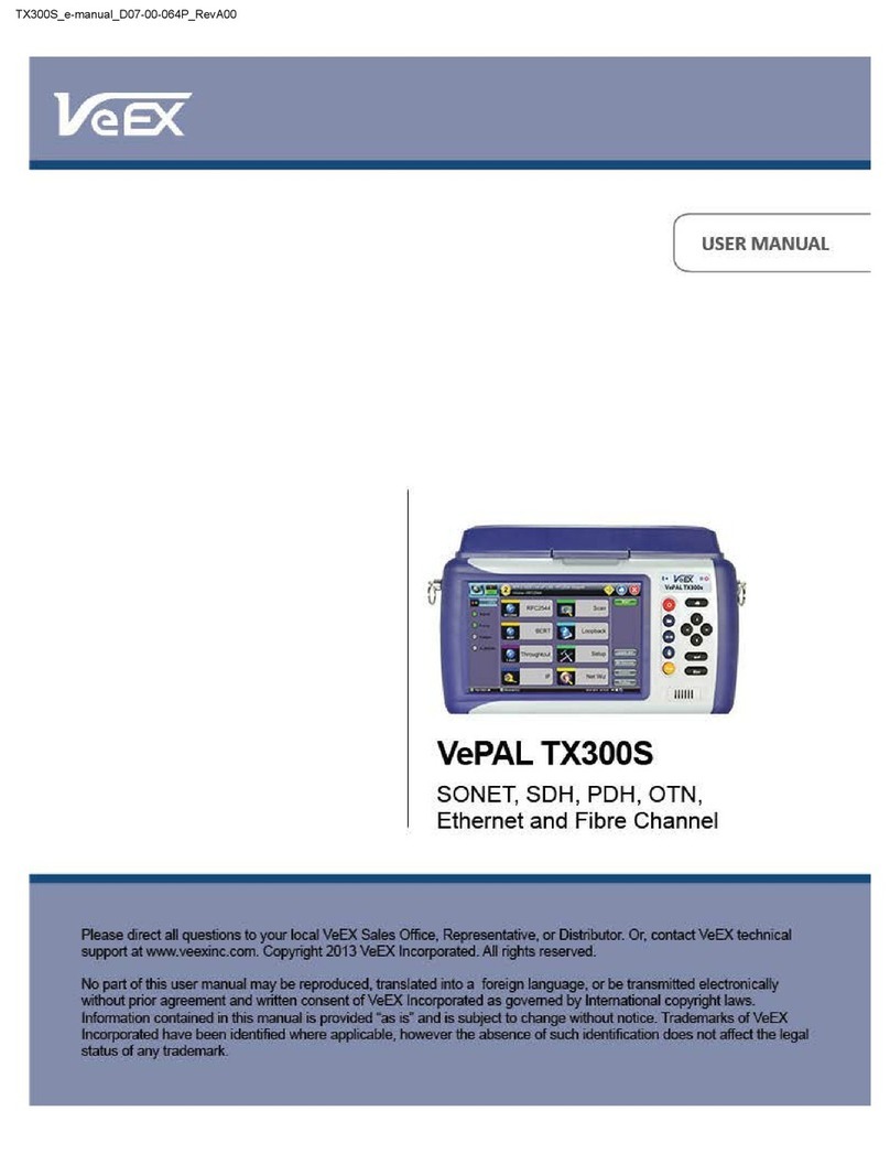
VeEX VePAL TX300 User manual

VeEX
VeEX RXT-1200 User manual

VeEX
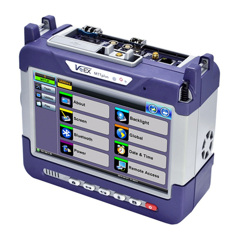
VeEX MTTplus User manual
VeEX
VeEX LX100 Guide

VeEX
VeEX VePAL BX100A Series Guide

VeEX
VeEX MPX100 User manual

VeEX
VeEX Fiber Scope Inspector User manual

VeEX
VeEX VePAL TX300M User manual

VeEX
VeEX MTX150x Lite User manual

VeEX
VeEX MTT-14B User manual
Popular Test Equipment manuals by other brands

Velleman
Velleman VTTEST3 Operation manual

VOLTCRAFT
VOLTCRAFT MS-440 operating instructions

VIAVI Solutions
VIAVI Solutions T-BERD Quick Card User Guide

Thermo Scientific
Thermo Scientific PCTestr 35 instruction manual

Agilent Technologies
Agilent Technologies 54853A Service guide

ZETRON
ZETRON Viavi 3550 Maintenance Guide