Tempsens CALsys 1700 User manual
Temperature
Calibrator
(CALsys 1700)
User's Guide
TEMPSENS INSTRUMENTS (l) PVT. LTD. UNIT ll
A-190, Road No.5, M.I.A., Udaipur-313003 INDIA
Ph. : +91-294-3500600,
Fax : +91-294-3500631
Email : tech@tempsens.com
Web : www.tempsens.com

Page | 1
Legal Disclaimer
The information contained in this document is the property of TEMPSENS.
TEMSPENS reserves the right to make changes to this document and to the product described herein
without notice. Before installing and using the product, review the latest version of the applicable
documentation, which are available from the Tempsens website at:
http://www.tempsens.com/
© 2021 Tempsens Instrument Pvt. Ltd. All Rights Reserved.
Document Information
Name
Temperature Calibrator (CALsys 1700) User Manual
Document Version
1.0
Document Code
TS.CS.004
Publish Date
Saturday, December 11, 2022

Page | 2
Preface......................................................................................................................................... 5
Safety Information.................................................................................................................. 5
Electrical Safety....................................................................................................................... 6
Health and Safety Instructions................................................................................................ 7
Cautions and Preventions....................................................................................................... 8
Document Conventions........................................................................................................... 8
Chapter 1
Introduction................................................................................................................................. 9
1.1 About CALsys 1700.................................................................................................................. 9
1.2 Basic Working Model of CALsys 1700...................................................................................... 10
1.3 Physical Measurements.......................................................................................................... 11
1.4 Wiring Diagram....................................................................................................................... 12
1.5 Technical Specifications for CALsys 1700 BB ......................................................................... 13
1.6 Technical Specifications for CALsys 1700L ............................................................................. 14
Chapter 2
Setting Up CALsys 1700................................................................................................................. 15
2.1 Installation.............................................................................................................................. 15
2.2 Optimal Environmental Conditions......................................................................................... 15
2.3 Unpacking and Initial Inspection............................................................................................. 16
2.4 Operating Instructions............................................................................................................ 17
Chapter 3
Operating CALsys 1700.................................................................................................................. 18
3.1 Turning On the Unit................................................................................................................. 18
3.2 Heating Up the Source............................................................................................................ 19
3.3 Operating Instructions............................................................................................................ 19
3.4 Cooling Down the Source ....................................................................................................... 20
Table of Contents

Page | 3
Chapter 4
Operating Unit Controller.............................................................................................................. 21
4.1 Operation of Controller........................................................................................................... 21
4.2 Wiring Layout of Controller..................................................................................................... 22
4.3 The temperature Controller.................................................................................................... 22
4.4 Altering the Set Point ............................................................................................................. 23
4.5 Monitoring the Controller Status ........................................................................................... 23
4.6 Temperature Units ................................................................................................................. 23
Chapter 5
Digital Communication................................................................................................................. 24
5.1 Digital Communications Wiring............................................................................................... 24
5.2 Digital Communications Parameters....................................................................................... 25
Chapter 6
Software Installation..................................................................................................................... 26
6.1 Installation.............................................................................................................................. 26
6.2 Parameters on main screen.................................................................................................... 27
Chapter 7
Service & Maintenance................................................................................................................. 28
7.1 Routine Service....................................................................................................................... 28
7.2 Replace the Controlling Sensor............................................................................................... 28
7.3 Replace Solid State Relay......................................................................................................... 28
Chapter 8
Troubleshooting CALsys 1700........................................................................................................ 30
8.1 CALsys 1700 unit does not turn on......................................................................................... 30
8.2 CALsys 1700 unit is not stable................................................................................................. 30
8.3 The temperature of the calibrator does not rise..................................................................... 30

Page | 4
Appendix A : Calibration Services ................................................................................................. 31
In House Calibration Facility.................................................................................................... 31
On-site Calibration Facility...................................................................................................... 32
Fixed-Point Calibration Facility................................................................................................ 32
Appendix B : Warranty ................................................................................................................. 33
Limit of Liability....................................................................................................................... 33
Caution in Using the Product.................................................................................................. 33
Page | 5
Preface
Welcome to the Temperature Calibrator (CALsys 1700) user guide. This guide provides detailed information
about all the product options and features, and explains how to use the product and configure basic settings
to suit your requirements.
This user manual contains information about the product and its proper use and should be kept in a place
where it will be easy to access. This user manual also provides safety precautions in using this product.
Safety Information
This chapter contains important information for the safety. If the instructions contained are not followed
properly, particularly the safety guidelines, it could result in serious personal injury or can cause serious
damage to the unit and to the components of system it is connected to. Use the instrument only as specified
in this manual. Otherwise, the protection provided by the instrument may be impaired.
Refer to the safety information below and throughout the manual.
In order to assure the device operates safely, the operator needs to act effectively and be conscious of safety
problems.
The terms “Warning” and “Caution” have the following definition:
l"Warning" indicates conditions or behaviors that could endanger the user.
l"Caution" denotes situations or behaviors that may endanger the instrument in use.
The following safety symbols may appear on CALsys 1700 unit:
SYMBOL
DESCRIPTION
SYMBOL
DESCRIPTION
Risk of Danger. Important
information. See Manual
Hazardous voltage. Risk of electric shock
Caution, Hot Surface
Protective Earth Ground

Page | 6
Electrical Safety
lBefore using this equipment, make sure it is properly grounded. Make sure the ground conductor
wire (colored green/yellow) in the main power cable is connected to a protective earth/ground. If
the equipment is not properly grounded, the high voltage may flow through the equipment body
(chassis). If safety procedures are not followed, SEVERE INJURY OR DEATH may occur.
lDo not remove the panels from the equipment without proper safety measures to avoid internal
main power supply voltage hazard.
WARNING:
Follow these precautions to avoid electric shock or personal injury:
This equipment uses protective earth circuit to ensure that the conductive parts do not store electric
charges or conduct electricity if insulation fails
lBefore connecting the equipment to the electricity supply, understand the parts of the calibrator with
the help of operating manual.
lUse power cables only with appropriate voltage and power rating, and that are approved for usage in
your country.
lReplace the main power cable if the insulation is damaged, or if the insulation shows signs of wear and
tear.
lDO NOT put the product at the location where access to the main power is blocked.
lDO NOT use an extension cord or adapter plug.
lDO NOT use the product if it operates incorrectly.
lMake sure the power cord does not touch the hot parts of the product.

Page | 7
Health and Safety Instructions
WARNING: BURN HAZARD - DO NOT touch the well access surface of the unit at high temperature
To avoid possible health and safety concerns, follow these guidelines.
lWear appropriate protective clothing before using the equipment.
lOperators of this equipment should be adequately trained in the handling of hot and cold items and
liquids.
lDo not use the apparatus for jobs other than those for which it was designed, that is, the calibration of
thermometers.
lDo not handle the apparatus when it is hot (or cold), without wearing the appropriate protective
clothing and having the necessary training.
lDo not drill, modify or otherwise change the shape of the apparatus.
lDo not use the apparatus outside its recommended temperature range.
lAfter use, do not return the apparatus to its carrying case until the unit has cooled down.
lThere are no user serviceable parts inside. When required, contact Tempsens agent for repair.
lEnsure all materials, especially flammable materials are kept away from the hot parts of the apparatus,
to prevent fire risk.
lDo not use the product around explosive gas, vapor, or in damp or wet environments.
lMake sure that the space around the product meets minimum space requirements.
lDO NOT turn off the unit at temperatures higher than 350°C. This could create a hazardous situation.
Select a set-point less than 100°C and allow the unit to cool before turning it off.
lThe top sheet metal of the furnace may exhibit extreme temperatures for areas close to the well
access.
lMaterials used in this furnace may be irritating to skin, eyes, and respiratory tract. Consult the material
manufacturer's Material Safety Data Sheet (MSDS) to learn about those materials before using.

Page | 8
Cautions and Preventions
To avoid possible damage to the instrument, follow these guidelines:
lBefore working inside the equipment, turn the power off and disconnect the power cord.
lDO NOT turn the unit upside down with the inserts in place; the inserts will fall out of the unit.
lUse of this instrument at HIGH TEMPERATURES for extended periods of time requires caution.
lCompletely unattended high temperature operation is not recommended for safety reasons.
lDO NOT plug the unit into 230 V if the heater switches and fuse holder reads 115 V. This action will
cause the fuses to blow and may damage the instrument.
lComponents and heater lifetime can be shortened by continuous high temperature operation.
lDO NOT use fluids to clean out the well.
lNever introduce foreign material into the probe hole of the insert. Fluids and other materials can leak
into the calibrator causing damage.
lDO NOT drop or force the probe stems into the well. This type of action can cause a shock to the sensor
and affect the calibration.
Document Conventions
The documentation uses the following conventions.
Note:
Configuration notes
Tip:
Recommendations or suggestions
Important:
Information regarding required or default configuration settings and product
limitations
WARNING:
Critical actions and configuration options
WARNING:
Page | 9
Chapter 1
Introduction
The CALsys 1700 used as calibrator for thermocouple calibration and it can be also used as a pyrometer
calibration with ceramic cavity.
The 'CALsys 1700' has been designed to provide stable and accurate temperature to enable professionals to
calibrate Temperature Sensing Devices (Thermocouple & pyrometer) by comparison method up to a
temperature range of 1700°C. The 'CALsys 1700L' model has been designed to be rugged and easily
maintained. This model provides an isothermal enclosure (Ceramic block) in which the thermocouple can
be calibrated against the temperature of the calibrator.
The 'CALsys 1700BB' model has been designed in single part. This model provides an isothermal enclosure
in which the Non-contact pyrometers can be checked against the temperature of the black body. For
traceable calibration a master pyrometer should be used. The units' features emissivity of 0.99, thus
offering the closest approximation of a target surface that is a perfect emitter of infrared energy.
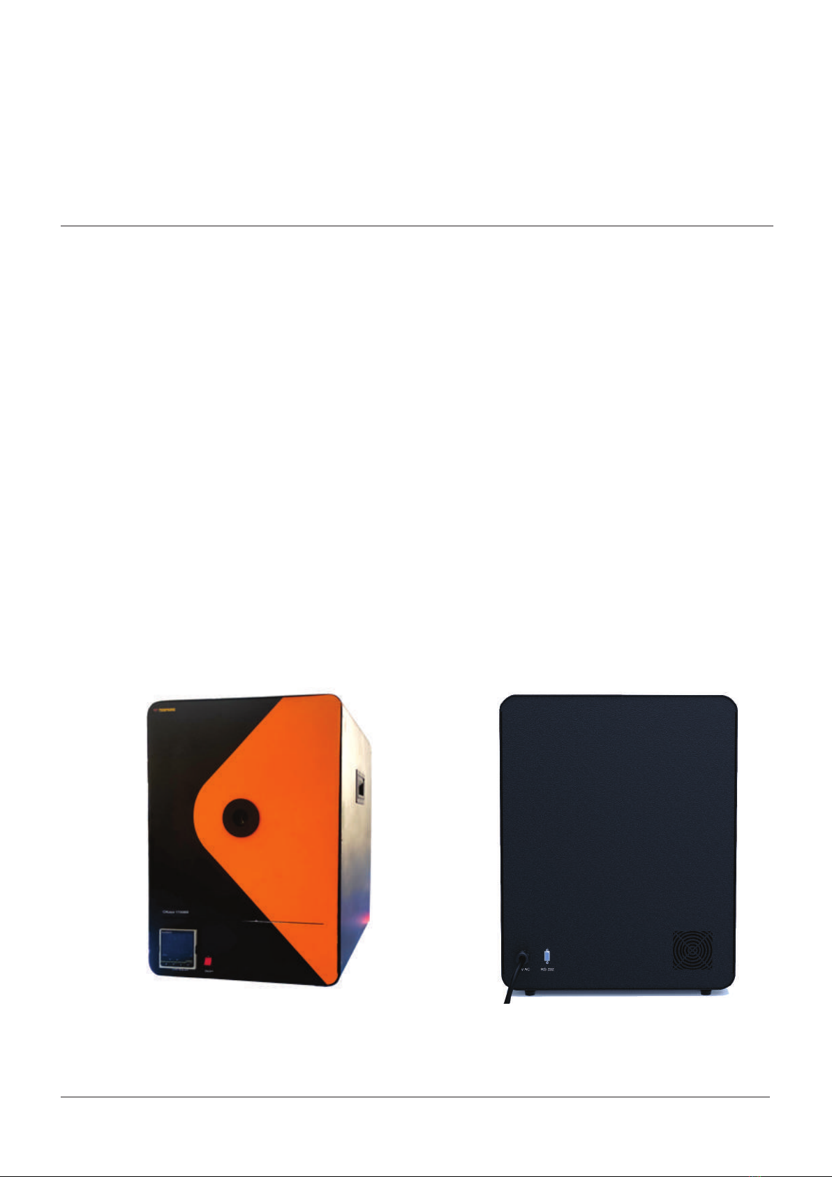
1.1 About CALsys 1700
Back View Front View
Page | 10
CALsys 1700' is a transportable unit designed for use on any reasonable flat surface. The target is a ridged
Ceramic Tube Cavity which is painted by a high emissive paint .The target is heated by MoSi heaters which
2
allow the source to heat up to 1700°C in about 3Hrs and hold it stable at temperature within ±2.0°C. The
heater block house consists of a heater and the controller sensor. This sensor is used by the temperature
controller to sense the block temperature. To maintain a required temperature the controller varies the
power to the heaters via a power control device.
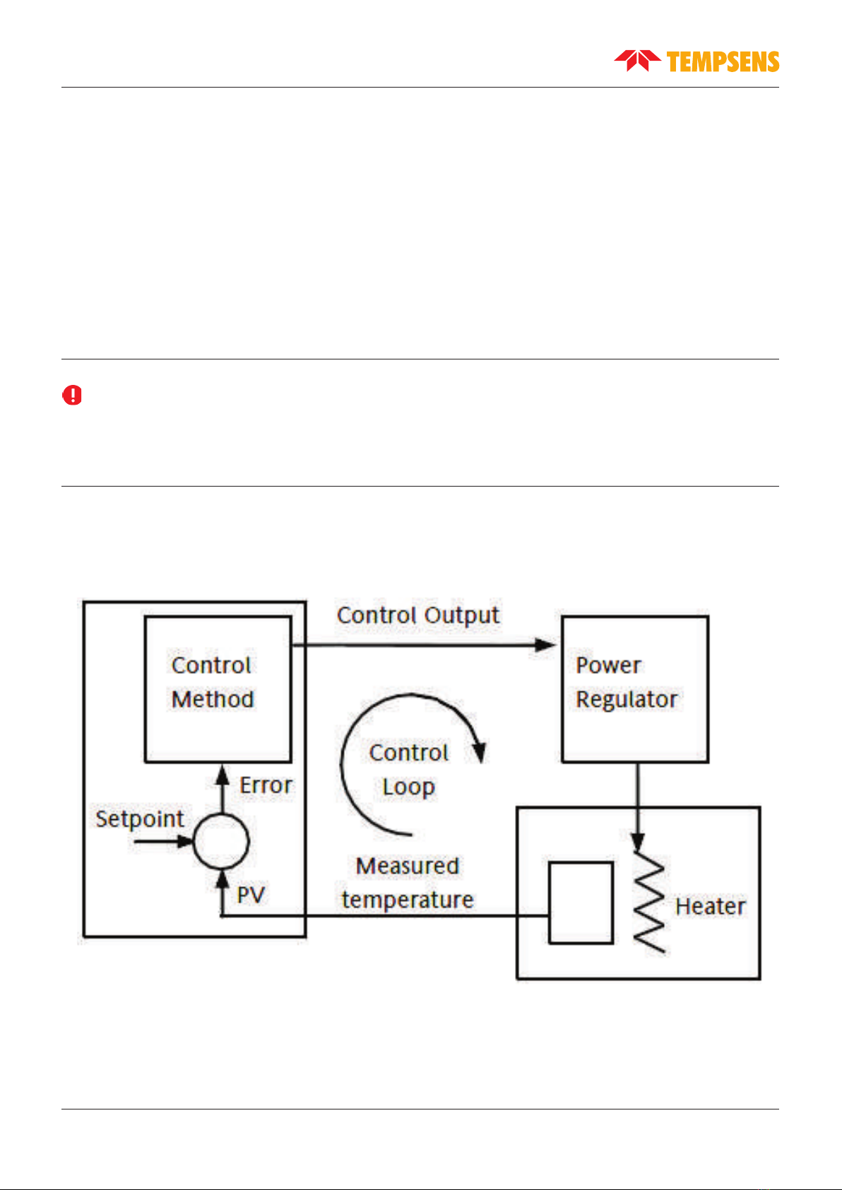
1.2 Basic Working Model of CALsys 1700
Before using the equipment, read the safety guidelines and operating procedures of the calibrator as
described in the of this user manual.
Important:
The basic working model for CALsys 1700 is as follows:
Page | 11
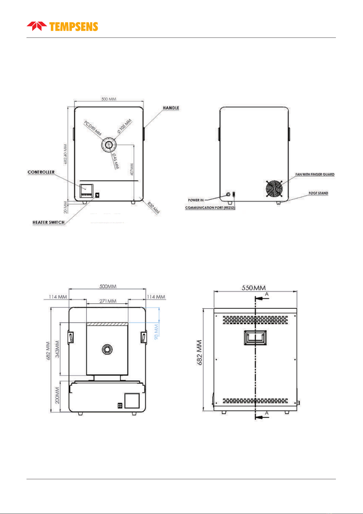
1.3 Physical Measurement
Front View Back View
Section A-A Side View
Page | 12
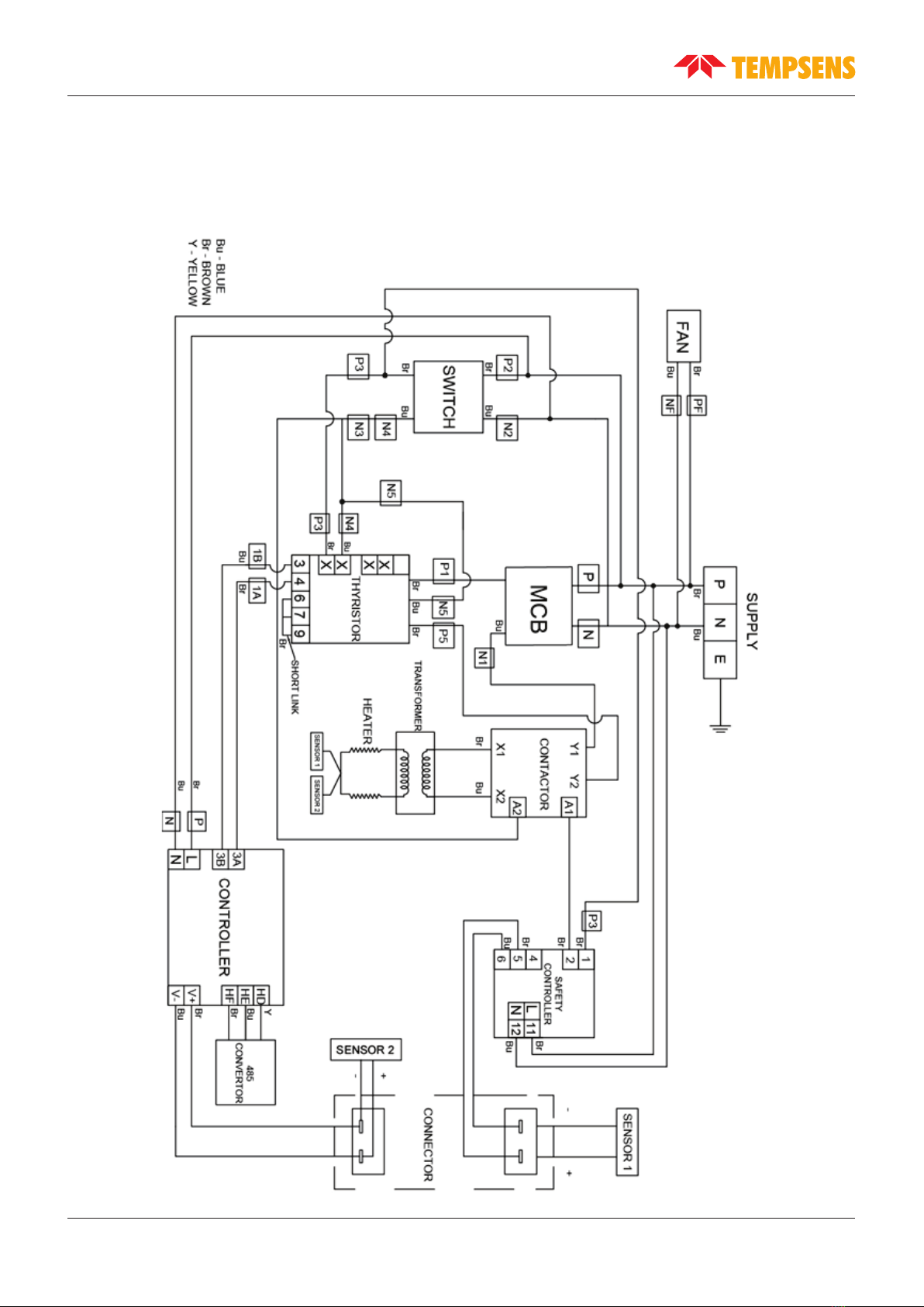
1.4 Wiring Diagram
Refer to following figure for CALsys 1700 wiring diagram.
Page | 13
1.5 Technical Specification
CALsys 1700 has the following technical specifications:
PARAMETER
SPECIFICATION
Voltage
230 V AC±10
Power
3 KW
Supply Frequency
50/60 Hz
Temperature Range
500°C to 1700°C
Resolution
0.1°C
Stability
±1.5°C
Uniformity
±2.0°C
Controlling sensor
Precision B type T\C
Time to reach max. temperature
3 hrs
Operating temperature
20°C to 45°C
Method of controlling
Digital self tuned PID controller
(Eurotherm P104 Controller)
Heaters
MoSi2
Computer interface
RS-232
Dimensions
640(H) x 500(W) x 550(D) mm
Insert construction
Diameter 37 x 240 mm long (2 x 6 mm & 2 x 8)
Weight
Approximate 80 Kg

1.5 Technical Specification
CALsys 1700L has the following technical specifications:
Temperature range 500 °C to 1700 °C
Stability
±0.5°C at 500°C
±1.0°C at 1000°C
±1.5°C at 1700°C
Radial uniformity
±0.6°C at 500°C
±1.4°C at 1000°C
±1.9°C at 1700°C
Stabilization time 15 to 20mins
Controlling sensor B type duplex
Method of Control Self tunned PID controller
Immersion depth 225mm
Insert OD dimensions 37 mm
Heating time 3 Hrs
Resolution 1 °C
Display LCD, °C or °F user-selectable
Size (H x W x D) 640(H) x 500(W) x 550(D) mm
Weight 130Kg
Power requirements 230 VAC 50/60Hz
Computer interface RS - 232
RS - 232 Accredited calibration certificate provided
Environmental operating conditions 0 °C to 40 °C, 0 % to 90 % RH (non-condensing)
Specifications valid in environmental
conditions 13 °C … 33 °C
Page | 14

Chapter 2
Setting up CALsys 1700
Place the calibrator on a flat surface with at least 10 inches of free space around the instrument. Overhead
clearance is required.
DO NOT Place this unit under a cabinet or structure. Plug the power cord into a grounded mains outlet
located on the controlling unit rear panel. Observe that the nominal voltage corresponds to that indicated
in the in of this user's guide.Technical Specifications Chapter 1
2.1 Installation
Although the instrument has been designed for optimum durability and trouble-free operation, it must be
handled with care. The instrument should not be operated in an excessively dusty or dirty environment.
Refer to in this user's manual for routine service and cleaning Chapter 8, Service & Maintenance
recommendations.
The instrument operates safely under the following conditions:
lTemperature range: 5°C - 50°C (41°F - 122°F)
lAmbient relative humidity: 15 - 50%
lPressure: 75kPa - 106kPa
lMains voltage within ± 10% of nominal
lVibrations in the calibration environment should be minimized
lAltitude less than 2000 meters
2.2 Optimal Environmental Conditions
Page | 15

CALsys 1700 is packed in custom-designed packaging to send out your unit. Unpack the furnace carefully.
Inspect the unit after unpacking for any signs of damage, and confirm that your delivery is in accordance
with the packing note. If you find any damage to the unit or an item is missing, notify Tempsens
immediately.
The following accessories are included in the package:
lCALsys 1700L/BB
lHeating Chamber
lHeaters (MoSi )
2
lRS-232 Cable
lB type thermocouple
lCeramic Cavity/optional block for dry block
lManual
lCertificates
lInsulation Wool
2.3 Unpacking and Initial Inspection
CALsys 1700L/BB Heating Chamber Heaters Insulation Wool
Cavity RS-232 B Type Thermocouple Optional Block
Page | 16

1. Please open the wooden box carefully and takeout the operating manual from the box and read
carefully.
2. Take out the temperature calibrator unit carefully and keep it at suitable place.
3. Install inner chamber as instructed in in of this user guide. Installation of CALsys 1700 Chapter -3
4. Connect the power plug to the mains.
5. Turn the switch ON, and observe the display on the controller. The display shows that the calibrator is
ready for use.
6. Keep the switch in the ON position
7. Ensure the ceramic insert/ceramic cavity is properly inserted in the calibrator.
2.5 Operating Instructions
lCeramic insert or ceramic cavity should be removed from the calibrator when it will reach ambient
temperature.
lUse either block or ceramic cavity (DO NOT use them together).
lAlways use safety gloves while handling the calibrator.
Note:
Ceramic Cavity for 1700BB Ceramic Block for 1700L
Page | 17

Chapter 4
Operating CALsys 1700
4.1 Turning ON the unit
Plug the CALsys 1700L power cord into mains outlet of the proper voltage, frequency and current capability.
Typically this will be (230 VAC±10, 50/60 Hz). Using the “ON/OFF” (for heater supply) switch located at front
side responsible for heating of furnace. The furnace will turn on and begin to heat the previously
programmed temperature set-point.
Earth
Neutral
Phase
Main Power Cable Connection
Controller ON/OFF switch
for heater
Page | 18
1. Connect the 'CALsys 1700BB' to a suitable power supply & set the controller to the required
Temperature.
2. After stabilization of the furnace, aim the reference standard thermometer to the center of cavity and
take the readings.
3. Repeat step 2 with the thermometer which is under calibration.
4. Find out the error by comparison method.
5. Always use a reference IR thermometer for comparison calibration method for 1700BB.
6. Check the D: S Ratio of the Pyrometer, it must be >10:1.
7. For CALsys 1700L place the ceramic insert in the calibrator.
8. Place the sensors for calibration and master sensor into a suitable insert hole.
4.3 Operating Instruction
4.2 Heating up the source
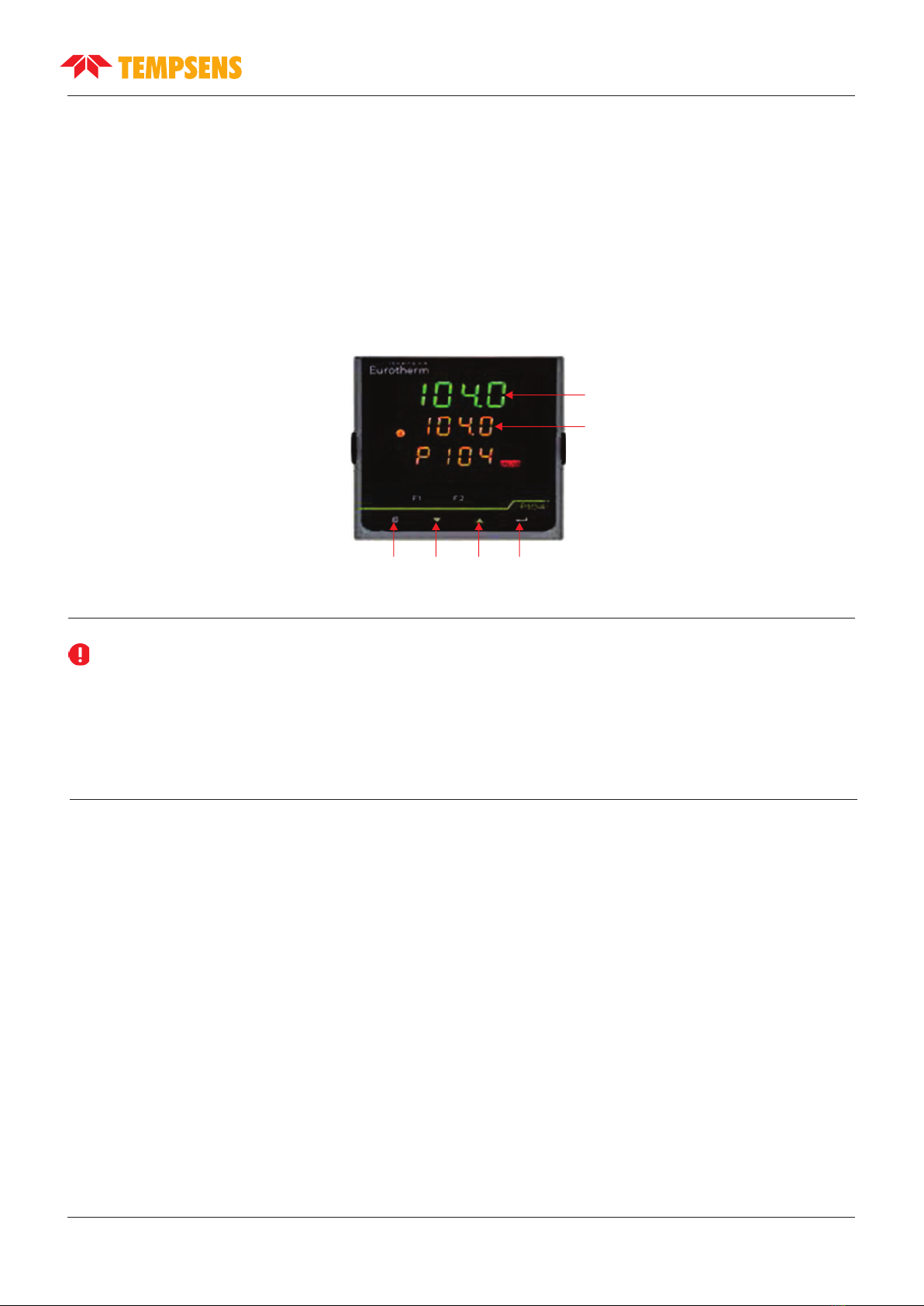
Press “UP” or “DOWN” key of controller to change the set-point value. When the set-point temperature is
changed the controller will switch the furnace heater on or off to raise or lower the temperature. The
displayed temperature will gradually change until it reaches the set-point temperature. The furnace may
require time to reach the set-point depending on the span. An another 5 to 10 minutes is required to
stabilize the furnace with ± 1.5 Deg C of the set-point.
Important:
lAll other controller parameters are company set and locked. It is recommended not to change them.
lWhen the source is operated at any temperature above ambient, the front face and plate become hot.
lAlways put the fan in “ON” Condition and do not switch the “Mains” off Directly, First set the controller
to 0°C and then wait until the unit is not cooled below 350°C.
Preset value of temperature
Set value of temperature
Page Down UP Enter
Front Panel Layout
Page | 19
Other manuals for CALsys 1700
1
This manual suits for next models
2
Table of contents
Other Tempsens Test Equipment manuals


Popular Test Equipment manuals by other brands

Keysight Technologies
Keysight Technologies Infiniium 90000A Series User's quick start guide

Fieldpiece
Fieldpiece SMAN440 Operator's manual

Agilent Technologies
Agilent Technologies E1852A installation guide

DATREND Systems
DATREND Systems ES601-US operating manual

Fluke
Fluke 707Ex Calibration information

Rohde & Schwarz
Rohde & Schwarz ESW user manual


