manual mode.
Write: Not allowed. See address 29.
Range: 0 to 1000 (0.0 to 100.0 %).
IDENTIFICATION
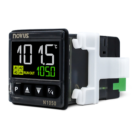
N1040 - A - B -C
A: Outputs Features
PR: OUT1= Pulse / OUT2= Relay
PRR: OUT1= Pulse / OUT2=OUT3= Relay
PRRR: OUT1= Pulse / OUT2=OUT3= OUT4= Relay
B: Digital Communication
485: Available RS485 digital communication
C: Power Supply electric
(Blank): 100~240 Vac / 48~240 Vdc; 50~60 Hz
24V: 12~24 Vdc / 24 Vac
SPECIFICATIONS
DIMENSIONS:............................................................48 x 48 x 80 mm
Cut-out in the panel: .....................45.5 x 45.5 mm (+0.5 -0.0 mm)
Approximate Weight: ...............................................................75 g
POWER SUPPLY:
Model standard:.......................100 to 240 Vac (±10 %), 50/60 Hz
................................................................... 48 to 240 Vdc (±10 %)
Model 24 V: ...................... 12 to 24 Vdc / 24 Vac (-10 % / +20 %)
Maximum consumption: ........................................................ 6 VA
ENVIRONMENTAL CONDITIONS:
Operation Temperature: ............................................... 0 to 50 °C
Relative Humidity:................................................... 80 % @ 30 °C
For temperatures above 30 °C, reduce 3 % for each °C
Internal use; Category of installation II, Degree of pollution 2;
altitude < 2000 meters
INPUT...... Thermocouples J; K; Tand Pt100 (according of Table 01)
Internal Resolution:...................................... 32767 levels (15 bits)
Resolution of Display:......... 12000 levels (from -1999 up to 9999)
Rate of Input Reading: ..................................up 10 per second (*)
Precision: . Thermocouples J, K, T: 0,25 % of the span ±1 °C (**)
................................................................Pt100: 0,2 % of the span
Input Impedance:..................Pt100 and thermocouples: > 10 MΩ
Measurement of Pt100: ......................... 3-wire type, (α=0.00385)
With compensation for cable length, excitation current of 0.170 mA.
(*) Value adopted when the Digital Filter parameter is set to 0
(zero) value. For Digital Filter values other than 0, the Input
Reading Rate value is 5 samples per second.
(**) The use of thermocouples requires a minimum time interval
of 15 minutes for stabilization.
OUTPUTS:
OUT1: ..................................................Voltage pulse, 5 V / 25 mA
OUT2: ................................Relay SPST; 1.5 A / 240 Vac / 30 Vdc
OUT3: ................................Relay SPST; 1.5 A / 240 Vac / 30 Vdc
OUT4: ...................................Relay SPDT; 3 A / 240 Vac / 30 Vdc
FRONT PANEL:......................... IP65, Polycarbonate (PC) UL94 V-2
ENCLOSURE:.............................................. IP20, ABS+PC UL94 V-0
ELECTROMAGNETIC COMPATIBILITY:............... EN 61326-1:1997
and EN 61326-1/A1:1998
EMISSION:............................................................ CISPR11/EN55011
IMMUNITY:...................... EN61000-4-2, EN61000-4-3, EN61000-4-4,
EN61000-4-5, EN61000-4-6, EN61000-4-8 and EN61000-4-11
SAFETY: .......................... EN61010-1:1993 and EN61010-1/A2:1995
SPECIFIC CONNECTIONS FOR TYPE FORK TERMINALS;
PROGRAMMABLE CYCLE OF PWM: From 0.5 up 100 seconds.
STARTS UP OPERATION: After 3 seconds connected to the power
supply.
CERTIFICATION:and .
SAFETY INFORMATION
Any control system design should take into account that any part of
the system has the potential to fail. This product is not a protection or
safety device and its alarms are not intended to protect against
product failures. Independent safety devices should be always
provided if personnel or property are at risk.
Product performance and specifications may be affected by its
environment and installation. It’s user’s responsibility to assure
proper grounding, shielding, cable routing and electrical noise
filtering, in accordance with local regulations, EMC standards and
good installation practices.


