0
()
FM
ALIGNMENT
NECESSARY INSTRUMENTATION
•
FM
Generator
(less
than
0.05%
THD.)
•
Stereo
Modulator
(less
than
;0.05%
THD.,
more than
50dB
Sep.)
•
Audio
Generator
(not
necessay
if
FM
Generator
has
built-in
sweep,
e.g.,
SOUND
TECHNOLOGY
ST 1000A
and
ST
iO2OA)
•
AC
VTVM’s
(or
one
with
a
LeftRight
switch)
•
THD
Analyzer
(resolution
less
than
0.1%)
•
Oscilloscope
(5mV
or
better
sensitivity,
X
input
capability)
•
Frequncy
Counter
•
VOM
or
DMM
(high
impedance,
must
read
in
mV)
•
75
ohm
Dummy
Antenna
IMPORTANT
1)
Before
alignments commence,
release
IF
NARROW
and
MONO
switches
(out),
Switch
FM NR
off
(in).
2)
IF
FM
Generator
is
not
synthesizer-type,
be
sure
to check
its
frequency
with
FREQ
counter
when adjusting
detector
and
multiplex
decoder
circuits.
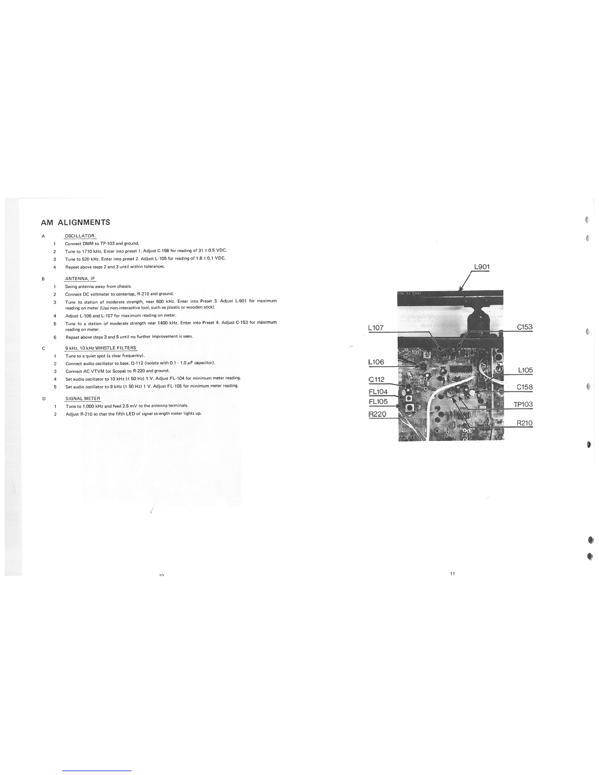
A.
SYNTHESIZER FREQUENCY
1.
Connect
Frequency
Counter between
TP-104
and
ground.
2.
Tune to
98MHz
(No
RE
input
needed).
3.
Adjust
C-201
so
that
the
local
oscillator
frequency shown
by
the frequency
counter reads
108.700MHz.
TOLERANCE:
108.700MHz
+/—2KHz
B.
FRONT-END
ALIGNMENTS
Alignment
of
the
front-end should
only
be
necessary
after
repair
to
the
front-end
or
crystal
oscillator
circuits.
a)
TUNING
VOLTAGE
It
is
essential
to
check
tuning voltage
before
aligning
the
rest
of
front-end.
1.
Connect
DMM
between
TP-105
and
ground.
2.
Tune to
88MHz,
and
adjust
L-6
if
the voltage
is
incorrect.
TOLERANCE:
3.6V
+/—0.5V.
3.
Tune
to
108MHz
and
confirm
that
the voltage
is
within
the
following
specification.
SPECIFICATION:
21-25V.
b)
TRACKING
1.
Connect
FM
Generator
(150KHz
sweep,
100V
output)
to
75ohm
antenna
input
and Detector Probe
to
Pin
1
of
IC
102
with
ground
to
the tunershield.
2.
Set
tuner
to
106MHz,
entor
into
Preset
8,
and
tune
the
generator
so
that
curve
appears
on
Oscilloscope.
3.
Adjust
C-2,
C-9,
C-li
and
C-14
for
maximum
curve
height
on
the oscilloscope
while
reducing
RF
input
to
keep
entire
curve
on
display.
4.
Set
tuner
to
90MHz,
enter
into
Preset
1,
and
tune the
generator
so
that
curve
appears
on
the
oscilloscope.
5.
Adjust
L-1, L-2,
L-3
and
L-4
for
maximum
curve
height.
6.
Repeat
above
steps
2, 3,
4
and
5
(use
Preset
1
and
8) till
both
frequencies
are
at
maximum
curve
height.
SUGGESTED INSTRUMENTATION
HOOKUP
ó
o
OSCILLOSCOPE
FM
GENERATOR
AUDIO
OSC
1
0
0
I
USE
ONL’?
IF
FM
GENERATOR
WITH
BUILT-IN
SWEEP
UNAvAILABLE
I
WITH
BUILT-IN
SWEEP
lE: ST
1000A
DISTORTION METER
I\1
DISTORTION
OUTPUT
SCHEMATIC
DIAGRAM
OF
DETECTOR
PROBE
Cl
02
330p
00
•o
4.
00
Diodes
should
be
point-contact
FROM
OUT
germanium;
Some
commonly
TUNER
C>’
TO
scoc
available
types
are:
0A80
0A8
1
AA1
19
1N60
1
N34
1N22
PICTORIAL
DIAGRAM
OF
DETECTOR
PROBE
Ri
CENTER
LEAD
TOPINI
Cl
02
jjEEEE
SCOPE
Keep
leads
as
shortas
possible,
to
minimize
stray
signal
pickup.
AT
FRONTEND
5
6