Tenco M2R User manual

TENCO S.r.l. Unipersonale
Via Arbora 1
16030 Avegno (GE) Italy
P.IVA03111170100
tel. +39-0185-79.556 r.a.
fax +39-0185-79.412
e-mail: i[email protected]t
Internet: www.tenco.it
BENCH
TOP
LABELLER
M2R

TABLE OF CONTENTS
CHAPTER1...................................................................................................................................................................................4
Declaration of Conformity.......................................................................................................................................................4
CHAPTER 2...................................................................................................................................................................................5
Marking....................................................................................................................................................................................5
CHAPTER 3...................................................................................................................................................................................6
Warranty..................................................................................................................................................................................6
CHAPTER 4...................................................................................................................................................................................7
GENERAL SAFETY INDICATIONS ......................................................................................................................................7
4.01 Pictograms..................................................................................................................................................................7
4.02 Residual risks.............................................................................................................................................................8
4.03 Demolition...................................................................................................................................................................8
CHAPTER 5...................................................................................................................................................................................9
TRANSPORT AND OPENING THE PACKAGE...................................................................................................................9
5.01 Packaging...................................................................................................................................................................9
5.02 Handling the crates or boxes.....................................................................................................................................9
5.03 Opening the package.................................................................................................................................................9
5.04 Handling the contents..............................................................................................................................................10
CHAPTER 6.................................................................................................................................................................................11
INITIAL INSTALLATION.......................................................................................................................................................11
6.01 Arranging the area...................................................................................................................................................11
6.02 Positioning................................................................................................................................................................11
6.03 Electrical connections..............................................................................................................................................11
6.04Paper quality ............................................................................................................................................................11
6.05 Direction of paper winding.......................................................................................................................................12
CHAPTER 7.................................................................................................................................................................................13
GENERAL.............................................................................................................................................................................13
7.01 Technical specifications...........................................................................................................................................13
7.02 Description of the machine......................................................................................................................................15
7.03 Composition of the machine....................................................................................................................................15
7.04 Control panel............................................................................................................................................................17
CHAPTER 8.................................................................................................................................................................................18
START-UP.............................................................................................................................................................................18
8.01 Turning the machine on and off ..............................................................................................................................18
CHAPTER 9.................................................................................................................................................................................19

WORK CYCLE......................................................................................................................................................................19
9.01 Container loading.....................................................................................................................................................19
9.02 Labelling...................................................................................................................................................................20
9.03 Container discharge.................................................................................................................................................21
9.04 Adjustments..............................................................................................................................................................22
CHAPTER 10...............................................................................................................................................................................33
MACHINE MAINTENANCE..................................................................................................................................................33
10.01 Schedule checks and maintenance......................................................................................................................33
CHAPTER 11...............................................................................................................................................................................34
TROUBLESHOOTING..........................................................................................................................................................34
CHAPTER 12...............................................................................................................................................................................35
SCHEMES.............................................................................................................................................................................35

CHAPTER 1
DECLARATION OF CONFORMITY
We
TENCO S.r.l. Unipersonale
Via Arbora 1, 16036 Avegno (GE) – Italia
declare on our own responsibility that the product:
Model: 900-01201-000
Serial no.
Year of manufacture: 2014
referred to in this declaration, complies as far as possible with the requirements outlined in the following Directives:
-98/37/ECMachinery Directive
-89/336/EEC Electromagnetic Compatibility Directive
-73/23/EECLow Voltage Directive
and that the following technical standards have been applied:
-ENISO 12100-1 Basic concepts,general principles for design. Basic terminology, methodology
-ENISO 12100-2 Basic concepts,general principles for design. Technical principles
-EN 294 Safety of machinery. Safety distances to prevent danger zones being reached by upper limbs.
-EN 349 Safety of machinery. Safety distances to prevent hazard zones being reached by upper and lower
limbs.
-EN 563 Temperatures of touchable surfaces. Ergonomics data to establish temperature limit values for hot
surfaces
-EN1050Safety of machinery. Principles for riskassessment.
AVEGNO,
The legalrepresentative of the Company
Giuseppe Tenco
Signature

CHAPTER 2
MARKING
Belowis an example of the CE-ATEX labelling reported on the machine frame.
TENCO S.r.l. Unipersonale
Via Arbora 1, 16036 Avegno (GE) – Italia
ANNO
ALIMENTAZIONE
MODELLO
POTENZA
MATR.
PRESSIONE ARIA
CONSUMO ARIA
MASSA
Conforme alle normative anti-infortunistiche CE

CHAPTER 3
WARRANTY
TENCO S.r.l. guarantees its products for 12 months from the date of delivery, indicated by the date on the shipping
document.
The TENCO warranty covers all defects of conformity of the machine with reference to the regulations in force on the
subject.The defectof conformity must be reported promptly and clearly to TENCO via registered letter: the company will
evaluate the defect and indicate the possible remedies in compliance with the directive in force. The manufacturer does
not acceptclaims for defects of conformity which, though obvious or readily detectable in use,are not reported promptly.
TENCO is not responsible for damages or defects due to improper installation and use, or malfunctions attributable in
any case to negligence of any kind.
TENCO is not responsible for damages to property or persons deriving from improper use of the machine or failure to
complywith the instructionsin the manualenclosed with the machine.
Repairs made under the warranty, involving additional expenses such as travel to the user’s premises, particular
shipments, etc., must be agreed on in advance with TENCO.
The warranty is automatically invalidated if the machine is tampered with, or in case of unauthorized repairs or use other
than that expressly indicated.
The personnel assigned to operate the machine must have psychological and physical characteristics compatible with
use of the machine, and must be instructed in its correct use. TENCO is not responsible for damages caused by
erroneous use of the machine.
For anything not expressly mentioned here, reference is made to the regulations in force on the subject.
In case of any disputes, the Court of Genova has jurisdiction.

CHAPTER 4
GENERALSAFETYINDICATIONS
This manualis an integral part of the machine and must accompany it throughout its life. Before performing any
operation,read each and every part of this manualcarefully.
The company cannotbe held responsible for property damage,injuries or damage to the machine itself due to non-
compliance with the instructions found herein.
The machine must be installed in good workmanlike manner and only by qualified personnel.
The operating personnel must receive adequate training in use of the machine and must be in good psychological and
physical condition and must not be under the influence of alcohol, drugs or medications that reduce alertness.
The operator must be aware of the dangers derived from use of the machine.
4.01 Pictograms
The safety-related pictograms posted on the machine (when required) and their meanings are reported below. If
the pictograms become illegible, they must be replaced (under the customer's responsibility).
Danger due to a voltage of 230V
Do not use water to put out fires – use the forms ofextinguishing indicated in the
standards
Danger related to transport; follow the instructions given in the manual; indication of
the machine centre of gravity, to be used when positioning the forks of the transport
forklift truck
Danger of pinching/crushing limbs

4.02 Residual risks
The figure below displays the residual risks that the machine may present during transport, operation and
maintenance.
4.03 Demolition
If the machine is to be demolished, it mustbe taken apart and the metal parts — steel, aluminum and copper —
separated from the plastic parts in PVC.
Recover the grease from the gearboxes found in the labeling station movement mechanism casing.
Finally, take the separated materials to special waste disposal centres.
RISK OF TIPPING
AND BEING CRUSHED
DURING TRANSPORT
when the centre of gravity indicated
by the pictogram posted on the
machine and the warnings
for transport are not heeded.

CHAPTER 5
TRANSPORT ANDOPENINGTHE PACKAGE
WARNING: before moving the machine, make certain that the unit being used israted forthe weight of the machine (see
the “technical characteristics” table) and note the manufacturer posted centre of gravity pictogram on the machine.
5.01 Packaging
5.02 Handling the crates or boxes
When handling with a forklift truck, make certain that the forks are set
symmetrically vs. this centre of gravity. Moreover, the forks should be far
enough apart to preventthe load from swinging or tipping over during
transport.
5.03 Opening the package
When opening the package, make certain that the contents match what is indicated in the shipping documents,
that they are not damaged, have not been tampered with or anything else. This must be done in the presence of
the carrier making the delivery (see WARRANTY). Dispose of the packaging materials as outlined in the current
standards.
MODEL
TYPE OF PACKAGING
M2R
N.1 pallet

5.04 Handling the contents
Withdraw allthe material from the package and bring the machine to the point where it is to be used; this mustbe
done following the same precautions followed when moving the packaged unit.

CHAPTER 6
INITIALINSTALLATION
6.01 Arranging the area
Arrange an area suitable for operation of the machine (see the “technical characteristics” table) as per European
standard EN60079.
Setthe unit ata point wherethe lighting is notless than200 lux.
The power cable supplied with the unit is 5 metres long and has no plug (IEC 309 2P + T 230 V). Check the
distance for access to the electricalpanel for hook up.
Do not use extension cords of any sort, flat or winding, as there is the risk of overheating.
Also arrange for connection to a compressed air system (only with marker installed on the machine).
6.02 Positioning
Moving the machine very carefully, take it to the arranged position (see 5.03 Handling the contents).
Set the machine in a stable position, check that it is level, make any necessary corrections and then lock the
wheels or adjustable feet.
6.03 Electrical connections
Make certain that the power supply system has a differential circuit breaker and an earthing systemcompliant
with the standards.
Check the electric characteristics of the machine (see “technical characteristics”table) and check that the power
supply is suitable and compliant with Directives 98/37/EC (Machinery Directive), 94/9/EC (ATEX Directive),
89/336/EC (Electromagnetic Compatibility Directive), 73/23/EEC (Low Voltage Directive).
After having checked the above, hook up the machine to the power supply using the cable and plug (IEC 309 2P
+ T 230 V) not provided.
6.04 Paper quality
If the quality of the paper used in the labels is not suitable for blade peeling, the labels can get twisted and
machine function will be poor. Always notify the label manufacturer of the problemof peeling.

6.05 Direction of paper winding
The rolls of labels (frontand back labels) must be printed and rolled up as shown below.

CHAPTER 7
GENERAL
7.01 Technicalspecifications
7.01.01TECHNICAL CHARACTERISTICS TABLE
Type of container (dimensions min-max)
Cylindrical: diameter from 35 mm up to 120 mm
Conical: NO
Squared: NO
Shaped: NO
Technical specifications
Production: 500 bph
Labelling tolerance: ± 3 mm
Work cycle: analogic board
Max.number of stations: 1
Paper passage: 170 mm max.
Printer: optional
Motor: DC motors encoder-controlled
Bottle ejection: manual
Pneumatic supply: none
Air consumption: none
Power supply: 230 V,50 Hz
Absorption: 0,5 kW
Packaging: Pallet
Weight: 25 Kg withoutpackaging
Maximumdimensions: see overall dimensions

7.01.02DIMENSIONALMEASUREMENTS AND OTHER SPECIFICATIONS
Photo 7.1 Main circuit breaker
Photo 7.2 Emergency push button

7.02 Description of the machine
This new model is really essential: our goal was to realize an extremely simple machine being able to work with
cylindrical container with a diameter between 35 mm and 120 mm. The base model can apply front and back
label, and, as the upper model LXT05, can work also with PET containers or containers made of low physical
resistance to pressure material. To be noticed is the stainless steel plate which retains the paper reel: it is
equipped with a friction system that let the paper roll scroll fluently, withoutbreaking the paper. The peeling blade
is made of stainless steel and, upon request, can be covered by a Teflon strip in order to reduce any paper
breaking even in case of particularly fragile papers. The paper detection photocell has a 40 mm height fork and is
auto-calibrating.
As it is really competitive on the market and basicly projected, this machine has no accessories except for the
stainless steel carriage.
7.03 Composition of the machine
01. Machine body
02. Controlpanel
Photo 7.4 Control panel
Photo 7.3 Machine body

Photo 7.5 Labellingside
Photo 7.6 Labels’ reel installed

7.04 Control panel
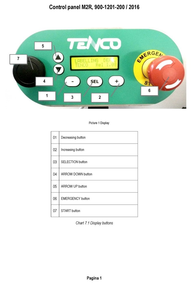
Table 7.1 Buttons and switches on control panel
01 Potentiometer DELAY OF LABELLING START-UP
02 Potentiometer for LABEL vs. BACKLABEL
CENTERING
A Switch to ENABLE INITIAL DELAY OF LABELLING
START-UP
B Switch to ENABLE 2 LABELS PACKAGING WITH
COMBO REEL
C Emergency push button
Photo 7.7 Control panel

CHAPTER 8
START-UP
After having installed the machine as described in chapter 6, you can proceed with start-up.
8.01 Turning the machine on and off
8.01.01PRELIMINARYOPERATIONS BEFORE TURNING THE MACHINE ON
To turn on the machine,you must:
-Trip the main circuit breaker photo 7.1 on the position 1.
-Disengage the emergency push-button Cphoto 7.7 on the upper side ofthe control panel.
8.01.02STOPPING THE MACHINE
It is possible to stop the machine while it’s working by acting on the emergency push button: in this case
all machine movement is stopped regardless of the work cycle progress status. It is not possible to know
exactly the work cycle phase when the machine has stopped, therefore, before turning on the machine, it
is necessary to raise the pressing roll, take the bottle off and re-position the label in order to make it stick
3-4 mmout of the blade(fig. 9.10 page 28).

CHAPTER 9
WORK CYCLE
The work phases for the labelling machine mod. M2R are listed below:
-Container loading
-Labelling
-Container discharge
9.01 Container loading
Open the pressing roll 1 and keep it opened
Insert the container in the labelling position
Pull the pressing roll down on the container: the labelling phase starts automatically.
Photo 9.1 Container loading

9.02 Labelling
Once you have inserted the container and pull the pressing roll down on it, the packaging goes ahead:
The container starts rotating and the selected labels are applied on it.
After all the labels have been applied,the container stops rotating to allow its discharge and the insertion
of a new container to be labelled.
Photo 9.2 Labellingside
Other manuals for M2R
1
This manual suits for next models
1
Table of contents
Other Tenco Label Maker manuals
