TENDO TSS-217 Instructions for use


CONTENT
QUICK START GUIDE
3
1 ACKNOWLEDGEMENT
3
2 SAFETY PRECAUTIONS
3
3 PRODUCT DESCRIPTION
4
3.1 About the product
4
3.2 Content of the basic TSS kit
5
3.3 Technical specifications
6
4 HARDWARE SETUP
6
4.1 Battery installation
6
4.2 Photocell/reflector installation
6
4.3 Tripod installation
7
4.4 Photocell
8
4.4.1 Photocell setup via menu panel
8
4.4.1.1 Switching ON
8
4.4.1.2 Photocell’s settings
9
4.4.1.3 Setup menu
9
4.4.1.4 Switching OFF
10
4.4.2 Power and battery LED lights
10
4.4.3 Battery charging
11
4.4.4 Battery exchange
11
4.4.5 Optical signalling LED bulb
11
4.5 TSS signal receiver
12
4.5.1 Signal receiver setup
12
www.tendosport.com
2
QUICK START GUIDE
1. Instal computer software
2. Instal TSS signal receiver driver
3. Setup the hardware
4. Start using TSS
1 ACKNOWLEDGEMENT
Thank you for purchasing Tendo product. We hope you will be satisfied with our product and
customer service.
Please read the user manual fully before using the product. Save the manual for future reference.
Make sure that other people using this product are familiar with the instructions.
2 SAFETY PRECAUTIONS
Do not use the device in a damp environment and in the rain.
Photocells, RFID chip reader and display board are equipped with
neodymium magnets via which they are attached to tripods.
The following safety precautions must be observed during the operation with the magnets:
1. Do not put 2 magnets together
2. When transporting devices containing magnets, use only non-metallic packages to form
protection around the magnet when transporting and storing the device
3. Medical devices - Some medical devices (such as pacemakers and heart defibrillators) may be
affected by a strong magnetic field
4. Credit cards and electronic devices - Do not place credit cards, computer disks, and other
magnetic storage devices closer than 20 cm to the magnet
5. Keep mechanical watches, compasses and hearing aids away from the magnet
•DC and DVD media do not carry magnetic data. Therefore, they cannot be damaged by the
magnet
•Cameras, mobile phones do not contain magnetically stored media. Therefore, they cannot be
damaged by the magnet
•USB keys and memory cards do not carry magnetic data and cannot be damaged by the magnet
•The static magnetic field does not damage the car keys
www.tendosport.com
3
3 PRODUCT DESCRIPTION
3.1 About the product
TENDO Sprint System (TSS) is a wireless computer system used to measure time of short
distances in training and testing of athletes. Information provided by TSS is essential in sports
where the performance is assessed thought speed, sprint, endurance, reaction, shuttle tests, etc.
TSS is an intelligent system, which uses error correction
processing technology that was found to eliminate false
triggers completely. TSS is able to recognise the interruptions
of the beam caused by different body parts while evaluating
only the interruption caused by the torso of the athlete.
Making it one of the most accurate systems on the market,
outperforming single-beam and even double-beam systems.
Turn Error Correction Processing ON/OFF based on your
training needs.
When the Error Correction Processing is turned off, the first
event is taken into account. Use it in training with athletes
using rackets, hockey sticks, bikes, wheelchairs…
TSS is a highly effective training technology used for performance evaluation and increase of
speed of athletes.
TSS also provides an immediate feedback about the athletes performance allowing trainers to
assess when it is the best time to terminate the exercise to prevent unnecessary injuries or
when a bit of extra motivation is needed to get the results you want.
3.2 Content of the basic TSS kit
www.tendosport.com
4
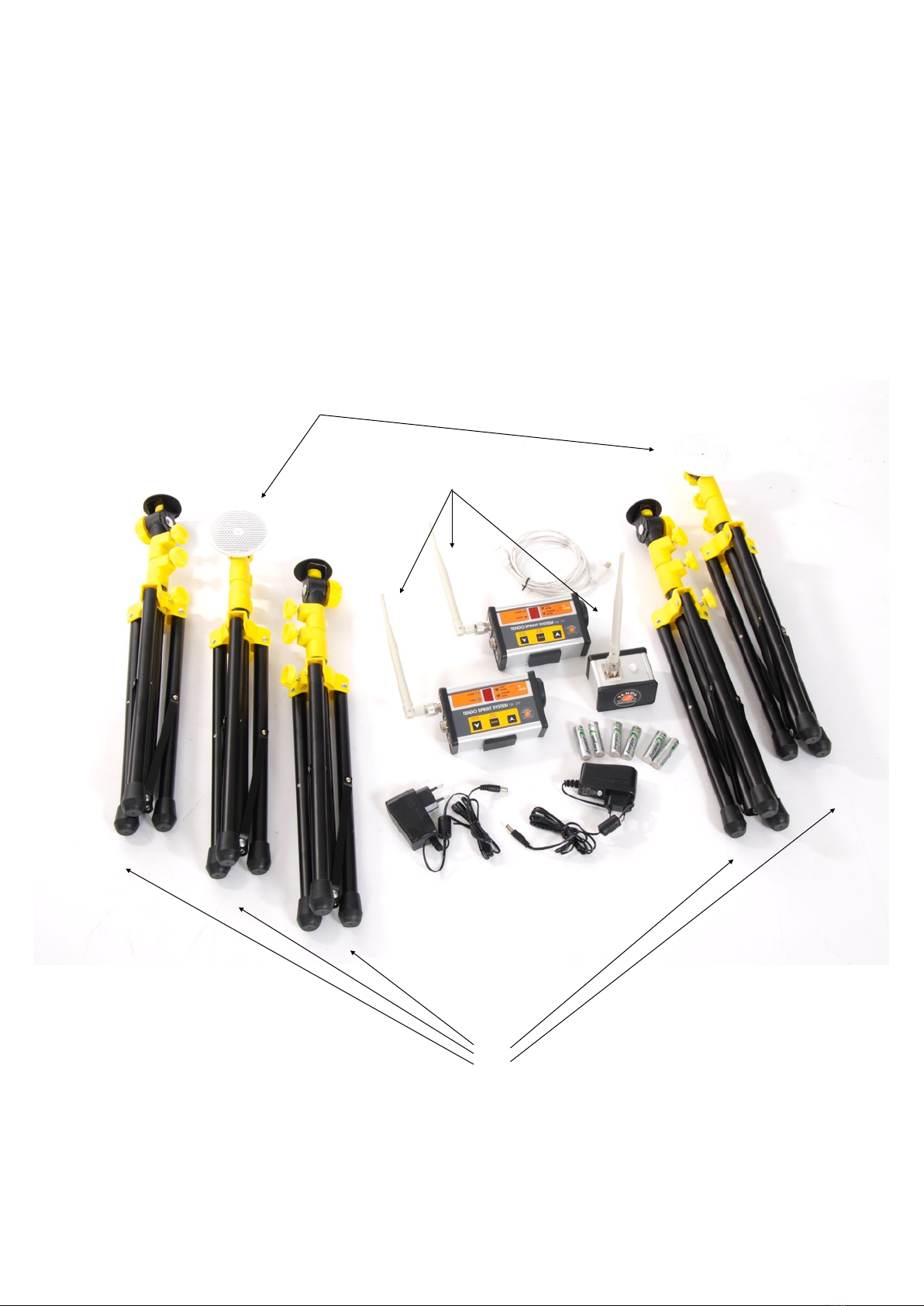
(1) 2 photocells
(2) 2 reflectors
(3) 1 TSS signal receiver
(4) 5 tripods
(5) 1 manual
(6) 1 computer software installation CD
(7) 1 carrier bag
(8) 2 sets of rechargeable batteries (4 pieces each set)
(9) 2 power adapters
(10) 3 antennas
(11) 1 signal receiver to PC connecting cable
www.tendosport.com
5
(1)
(3)
(11)
(2)
(10)
(4)
(8)
(9)

The kit can be expanded by purchasing more photocells and reflector pairs with tripods. Please
contact your seller for more information
3.3 Technical specifications
•Maximum distance between photocell and reflector is 5 m
•Maximum distance between photocell and TSS signal receiver is 100 m
•Accuracy of measurement: 1/1000 s
•Maximum number of photocells for split times: 8
•Number of communication channels: 4
•Frequency range based on continents/countries: Europe, USA, China, India, AU AS (Australia,
New Zealand, Indonesia, Hong Kong, Japan, Malaysia, Taiwan, Thailand, Singapore,
Vietnam)
4 HARDWARE SETUP
4.1 Battery installation
New rechargeable batteries are already inserted in the photocell’s battery compartment. The
batteries are secured with a plastic safety strip to prevent the photocells switching on
spontaneously during transport.
Before the first use, carefully pull out the plastic safety stripe.
Use only rechargeable batteries type NiMH, size AA, 2000 - 2500 mAh
4.2 Photocell/reflector installation
A photocell and a reflector always form a pair. Both, photocells and reflectors, are mounted on
steel tripods.
Frequency Range
Communication
Channel
Europe
USA
China
India
AU AS
0
869.6
914.6
868.0
865.2
921.2
1
869.8
915.2
868.2
865.8
922.4
2
869.6
915.8
868.4
866.4
923.6
3
869.8
916.4
868.6
867.0
924.8
www.tendosport.com
6
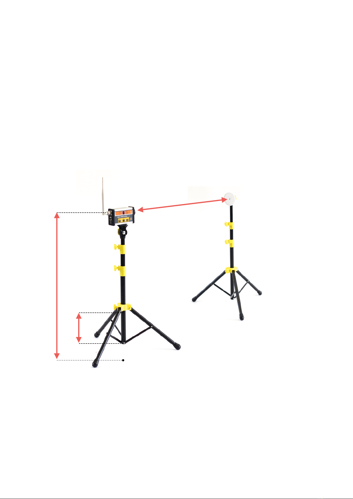
4.3 Tripod installation
1. Open the tripod so the bottom yellow plastic part is approximately 25 cm from the bottom end
of the tube (see the picture below). Secure the position by tightening the locking screw.
2. Attach the photocell to a steel plate located on the top of the tripod via magnet located on the
bottom of the photocell.
3. Screw antenna onto the top connector of the photocell (see page 8). But not tighten the nut yet!
Set the antenna to the perpendicular position first, then tighten the nut.
!! If you tighten the nut before the antenna is set to the correct position, it could cause
damage to the antenna !!
4. Set the height of the tripods based on your needs (We recommend placing the photocells/
reflector pairs in height of 100 - 110 cm from the ground). Make sure that the photocells and
reflectors are in the same height so the beam of the photocell falls in the middle of the reflector.
Do not place photocells on the ground as the radio signal will be low.
5. Place the reflector at a distance of 2 - 5 m from the photocell (Do not exceed the 6 m distance).
•If the photocell is switched on and the beam does not fall onto the reflector, the photocell will
produce a continuous audio signal. Thanks to the audio signal, it is easy to alight the
photocells and reflectors properly (no audio signal indicates a correct alignment of the photocells
and reflectors).
•Each time the photocell’s beam is broken, an audio signal is produced and the optical signalling
LED bulb (9) will be lit.
4.4 Photocell
www.tendosport.com
7
25 cm
10 in
2 - 5 m
2.2 - 5.5 yards
100 - 110 cm
39 - 43 in
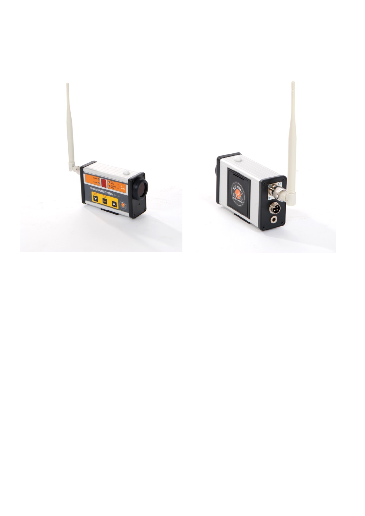
(1) Menu panel
(2) Battery compartment
There are three connectors located on the rear side of the photocell:
(3) Antenna connector
(4) Connector for RFID reader
(5) Power supply adapter connector
Optical sensor (6) and speaker (7) are located on the front side of the photocell.
Fastening magnet (8) is placed on the bottom of the photocell.
On the top there is an optical signalling LED bulb (9).
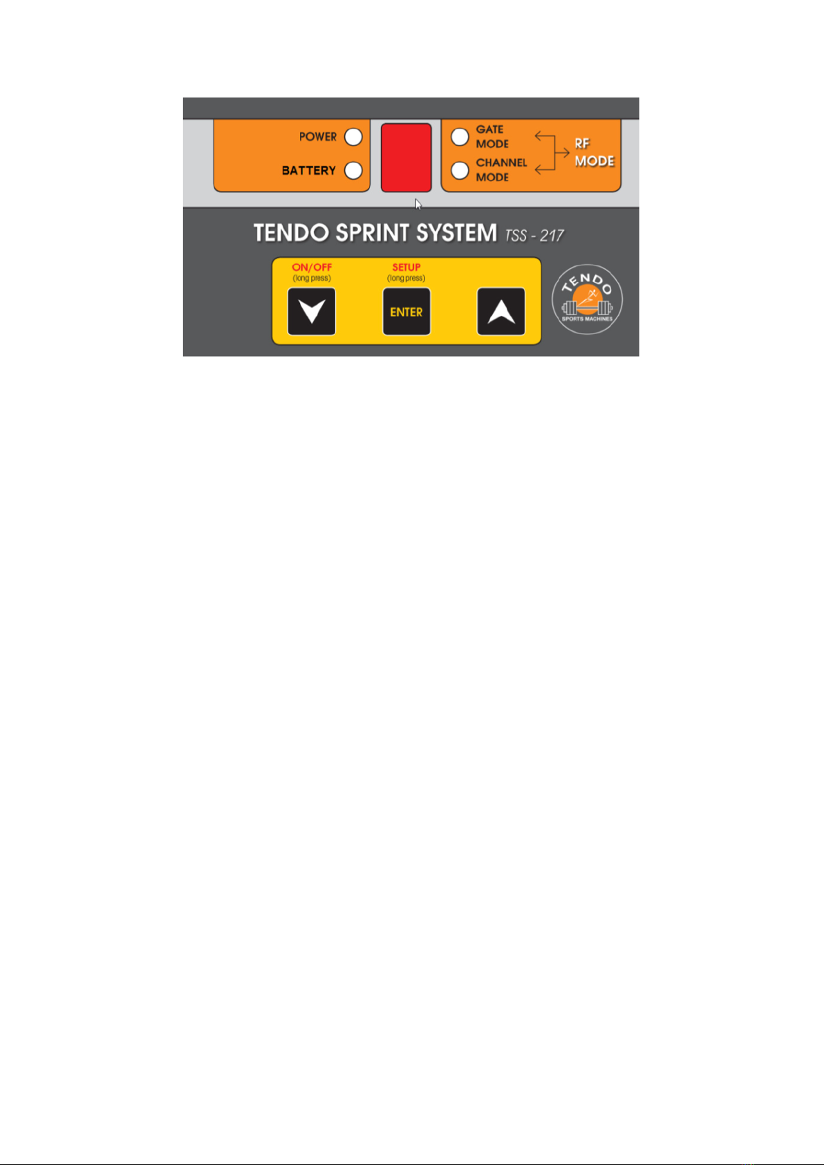
4.4.1 Photocell setup via menu panel
4.4.1.1 Switching ON
Press ON/OFF button (button of the left - downwards arrow) for 2 < seconds. After the long press
(press and hold 2s <), you will hear a double beep and LED_power will light up. The photocell is
ready for use now.
Immediately after the ON/OFF button is released, information about a current setting of the
photocell is shown on the LED display for 5 seconds.
www.tendosport.com
8
(1)
(2)
(3)
(4)
(5)
(6)
(7)
(8)
(8)
(9)
(9)
4.4.1.2 Photocell’s settings
•The setting of the photocell represents the photocell’s function:
0= start
1 - 8 = split times
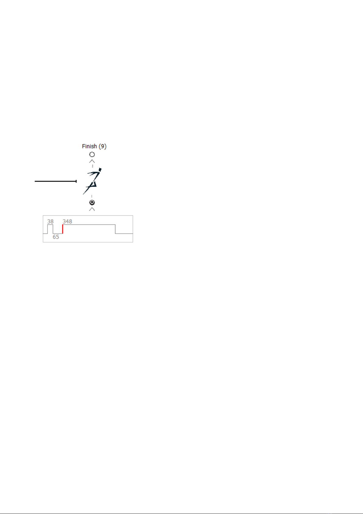
9 = finish
•To see the current setting of the photocell, press the ON/OFF button anytime (short press only).
The setting will be displayed for 3s.
4.4.1.3 Setup menu
Use a long press of the Setup button (button in the middle - ENTER) to activate Setup Menu of the
photocell.
Function of the buttons in the Setup Menu:
•Down/ Up button - to change values in the submenu
•ENTER - Short press - to browse in the menu
•ENTER - Long press - to close the setup menu and save all new settings
!! If you wish to save the new settings, make sure you long press ENTER button !!
If the setup menu is activated and no buttons were pressed for more than 30s, the setup menu will
be closed and the new settings will be lost.
If you are in the Setup Menu you have 3 options:
1. Change the setting of the photocell (start, split, finish) = GATE MODE
2. Setup the channel for communication (specific frequency) = CHANNEL MODE
3. Change country in which TSS is used (different frequency ranges are used in different
continents/countries due to different norms) = RF MODE
When you open the submenu, the LED light indicates a particular setting option.
To change settings use Up or Down buttons.
1. GATE MODE - choose from 0 to 9 (0 = start, 1 - 8 = split times, 9 = finish)
www.tendosport.com
9

It is possible to use any photocell number for start, finish and split times. However, it needs to be
synchronised with the gate setting in the Tendo Sprint System computer software (the same
number for start, finish and split times).
2. CHANNEL MODE - choose from 0 to 3 (see page 6)
3. RF MODE - E - Europe, A - USA, C - China, I - India, U - Australia, New Zealand, Indonesia,
Hong Kong, Japan, Malaysia, Taiwan, Thailand, Singapore, Vietnam (option)
4.4.1.4 Switching OFF
Press ON/OFF button (button of the left - downwards arrow) for 2 < seconds. After the long press
(press and hold 2s <), you will hear a double beep and LED_power will turn off. The photocell is
now switched off.
4.4.2 Power and battery LED lights
Power LED
If the photocell is turned on and the system is not connected to the computer software, Power LED
light lit continuously with a green light.
If the photocell is turned on and the system is connected to the computer software, Power LED
light flashes with green light.
Insufficient power supply (under 4.4V) is indicated by Battery LED light flashing with orange light
and the batteries need to be charged.
If the power supply adapter is plugged in and the charging progress began, the Battery LED light lit
continuously with orange light.
www.tendosport.com
10

After the batteries are fully charged, the Battery LED light is turned off.
Battery LED = Battery status indicator
Battery LED light - OFF = batteries are charged
orange Battery LED light - Flashing = batteries need to be charged
orange Battery LED light - ON = batteries are charging
4.4.3 Battery charging
Each photocell has its own built-in battery charger. To charge the batteries use the power adapter
which is part of the basic TSS set kit.
Power adapter parameters:
Input voltage: 110 - 230 V AC, 50 - 60 Hz
Output voltage: 12 V DC, 1,2 A
!! Only use rechargeable batteries: type NiMH, 2000 - 2500 mSh !!
Plug the power adapter into a 230V AC power outlet
Plug the power adapter connector into the bottom socket on left side of the photocell unit (see
page 8)
After the charging process is turned on, the LED_battery light will indicate the charging via
continuous orange light and LED display shows “c” for 2 seconds..
After the charging process is finished, the orange LED_battery will turn off.
4.4.4 Battery exchange
1. Open the back cover of the battery compartment
2. Insert 4x rechargeable NiMH batteries as pictured on the bottom part of the battery
compartment
3. Before inserting the batteries, make sure that the batteries are correctly polarised
4.4.5 Optical Signalling LED bulb
1. If the photocell is turned off or on but not connected to the TSS computer software, the optical
signalling LED bulb (9) located on the top of the photocell unit is turned off.
2. The photocell is turned on and connected to the TSS computer software.
- the optical signalling LED bulb lit continuous red light along with a high frequency audio
signal = photocell beam between the photocell and the reflector is interrupted or the beam
is out of the reflector
- the optical signalling LED bulb flashes red light along with flashing Power LED light =
indicates correct communication between the photocell unit, receiver and TSS computer
software (after the “Click to Connect” button in the TSS computer software was activated).
www.tendosport.com
11

4.5 TSS signal receiver
TSS signal receiver is used to receive data from the photocells wirelessly. The TSS signal receiver
is connected to a computer via a USB cable.
4.5.1 Signal receiver setup
Screw antenna onto the top connector of the signal receiver and tighten the antenna nut. Attach
the signal receiver to a steel plate located on the top of the tripod via a magnet. The magnet is
located on the bottom of the signal receiver
It is recommended to place the signal receiver is the same height as the photocells for a better
radio signal.
A multicolour LED light is placed on the top of the
signal receiver:
1. Blue flashing light = active and correct communication
with all turned on photocells.
2. Blue/Red flashing light = at least one of the photocells
in not communicating with the TSS computer software
(e.g. the photocell is turned off or the communication
channel, frequency range or the photocell number does
not correspond to the setting in the TSS computer
software)
3. Red continuous light = After clicking “Connect” in the
TSS computer software, the continuous red light
indicates no communication between the signal receiver
and the photocells (e.g. the photocells are turned off).
Before the first use it is necessary to install TSS signal receiver driver
1. Insert the USB cable into the connector located on the signal receiver
www.tendosport.com
12
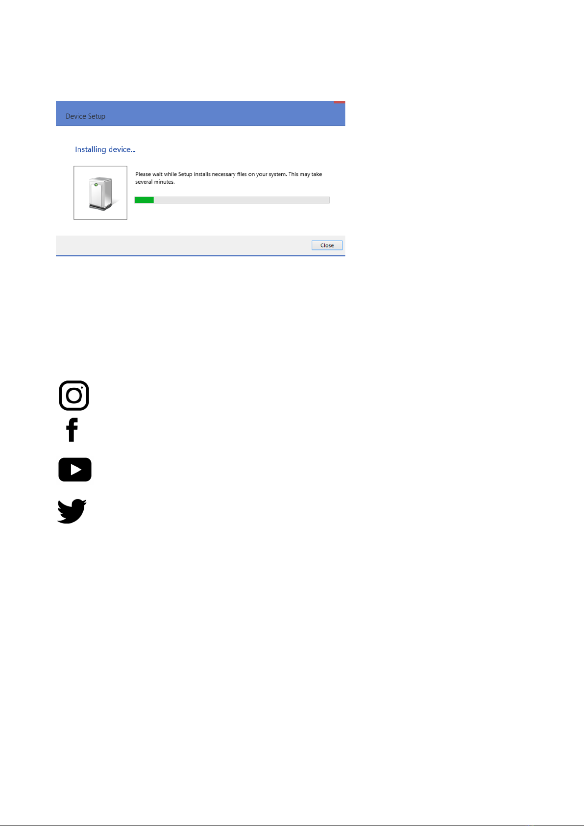
2. Insert the other end of the USB cable to a USB port on your computer
3. Your computer will recognise the new device and install the TSS signal receiver driver
Once the driver is installed the system is ready for use
Manufactured in Europe.
TENDO Sport
Zlatovska 22 "
911 01 Trencin Phone / fax : 00421-32-6401500"
www.tendosport.com
13
@tendosport_official
TENDO Sport
@tendosportsmachines
@tendosport
Tendo Sports Machines
@TendoSport
Table of contents
Other TENDO Data Logger manuals


