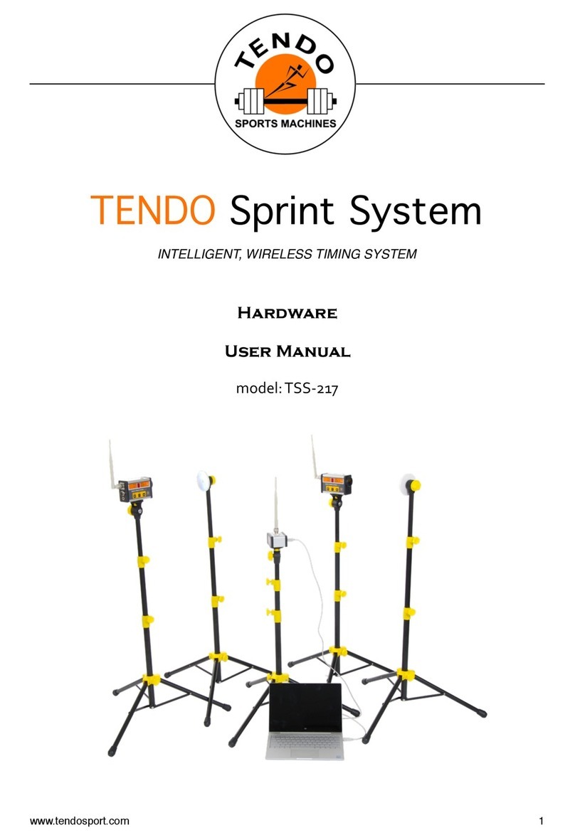
TENDO Sprint System User manual

1
QUICK START GUIDE for TENDO SPRINT SYSTEM
1. Install computer software
2. Install TSS signal receiver driver
3. Setup the hardware
4. Start using TSS
1. Install computer software from the installation flash disc or visit
https://www.tendosport.com/support/software-updates/tendo-sprint-system/
2. Install TSS signal receiver driver. It is a part of the software installation.
TSS signal receiver is used to receive data from the photocells wirelessly. The TSS signal
receiver is connected to a computer via a USB cable.
Signal receiver setup
Screw antenna onto the top connector of the signal receiver and tighten the antenna nut.
Attach the signal receiver to a steel plate located on the top of the tripod via a magnet. The
magnet is located on the bottom of the signal receiver.
It is recommended to place the signal receiver is the same height as the photocells for
a better radio signal.
3. Setup the Optogate
- Open the tripod so the bottom yellow plastic part is approximately 25 cm (10 in) from the
bottom end of the tube. Secure the position by tightening the locking screw.
- Attach the photocell to a steel plate located on the top of the tripod via magnet located on
the bottom of the photocell.
- Screw antenna onto the top connector of the photocell. But not tighten the nut yet!
Set the antenna to the perpendicular position first, then tighten the nut.
!! If you tighten the nut before the antenna is set to the correct position, it could cause
damage to the antenna !!

2
- Set the height of the tripods based on your needs (We recommend placing the photocells/
reflector pairs in height of 100 - 110 cm from the ground). Make sure that the photocells and
reflectors are in the same height so the beam of the photocell falls in the middle of the
reflector.
- Place the reflector at a distance of 2 - 5 m from the photocell (Do not exceed the 5 m
distance).
- Press ON/OFF button (button of the left - downwards arrow) for 2 < seconds. After
the long press (press and hold 2s <), you will hear a double beep and LED_power will
light up. The photocell is ready for use now.
Immediately after the ON/OFF button is released, information about a current setting
of the photocell is shown on the LED display for 5 seconds.
To see the current setting of the photocell (Gate Mode), press the ON/OFF button anytime
(short press only). The setting will be displayed for 3s.
Change the Gate Mode, Chanel Mode and Radio Frequency is possible to do in the setup
mode.
Use a long press of the Setup button (button in the middle - ENTER) to activate Setup Menu
of the photocell.
Use the selected Radio Frequency only in a country where the particular frequency is
allowed.
DO NOT USE THE RADIO FREQUENCY NOT ALLOWED IN THE COUNTRY OF THE
SYSTEM LOCATION.
Important Notice
It is possible to use any photocell number for start, finish and split times. However, it needs
to be synchronised with the gate setting in the Tendo Sprint System computer software (the
same number for start, finish and split times).
Recommendation
Maximum reliable signal transmition distance between the photocell and a Receiver is 100m.
However if you want to measure longer distance e.g. 200m, place the receiver in the middle
between the start and finish optogate (100m).

3
Double click on the Sprint System icon to open a program window.
By clicking Admin Center, new window will open. Here you can add athletes’ details and
create groups. The added groups and individual athletes will be then possible to use
throughout the program.
Software System Setup
Click “SETTINGS”. A new window for setting measurement units opens. Here you can
choose whether the program will use English system "Imperial" or metric system “Metric”,
meters or kilometres.
Select the chosen system, distance and speed units and click OK.
Error Correction Processing (ECP) = use algorithms to eliminate measurement errors and
false signals due to swinging arms or legs.
Click on a square to turn ECP ON or OFF.
CREATE A TRAINING/TEST TEMPLATE
Before starting a training/test, choose a template from our database or create your own
database of training/test templates.
To create a training use “Activity" window (located in the middle of the top part of the
program window)

4
Enter the name of the training/test. In order to be able to identify the template later.
• Enter number of photocell/reflector pairs used in the training/test “# of Gates”
• Enter number of runs used in the training/test “# of runs”
• If Lap Run (Start optogate = Finish optogate) is selected, it is possible to set the number of
laps and lap distance.
Select a type of the photocell (its function) - the type/function of the photocell MUST be the
same as the photocell’s setting. It is a number from 0 to 9 (see Hardware Manual for
photocell’s settings)
We recommend that you mark the start photocell with the number "0" and the finish photocell
with the number "9". Numbers 1-8 can be assigned to split photocells.
For a correct communication of the computer software with the photocells, it is essential that
the numbers of the photocells that represent their function are identical with the settings in
the computer (Gate ID)
Select the distance between the photocells (start, finish, split). Enter the values, press
Enter or click anywhere in the program window to confirm.
• The program calculates “Total distance” automatically
Setting a correct distance is necessary for calculating the correct speed.
Please read the software user’s manual for the software setting.
Click to SAVE TEMPLATE - Saves a new training/test template to a Data/Templates
database.

5
Communication settings are independent of Template settings, and the TSS software
remembers the previously set communication settings.
Click Group / Persons to select a group (or a specific person).
Click “APPLY” and persons will be imported in the result table at the bottom of the program
window.
Click “CONNECT”
Connection is OK
program indication - START button above the result table flashes green and red.
Photocell’s indication that the connection is OK - the top LED bulb flashes red while
the LED Power flashes green
THE MEASUREMENT
If the connection is OK, you have set a training/test and entered athletes, you can start the
measurement.
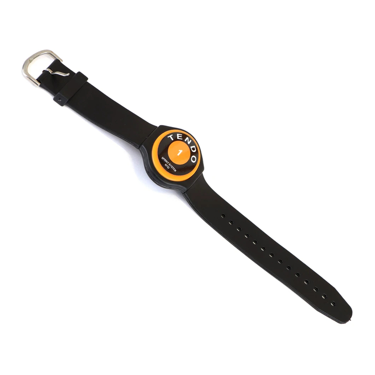
1. Select a person by click on their name. If you have RFID chips, after touching the
chip reader with a RFID chip bracelet, athletes will be switched automatically based
on their assigned chip.

6
If you do not click the START button, the results will not be recorded in the result table. It is
like a trial mode, but not all features are allowed in the Trial Mode.
2. Click “START” to start the measurement which will be written down to the results table
• After the “START” button is pressed, the “START” button changes into a “PAUSE” button
via which the measurement can be stopped at any time.
Re-click the “PAUSE” button to resume the measurement which will be written down to the
result Table
Quick Start Guide does not supersede manuals. Please read the software and hardware
manuals before you start to use the Tendo Sprint System.
Other manuals for Sprint System
1
Table of contents
Other TENDO Data Logger manuals
