Tenma 72-3555 User manual

1
USB Dual Channel Waveform
Generator
Model: 72-3555

2
CONTENTS
Page Number Details
3 What’s Included
3 Important Safety Information
3 Introduction
4 Key Features
4 Product Overview
6 Rear Panel
7 AC Power Receptacle
9 Start
10 Setting DC Offset Voltage
10 Setting the Square Wave
11 Setting the Pulse Waveform
11 Setting DC Volts
12 Setting the Ramp Waveform
12 Setting the Noise Waveform
12 Frequency Measurement
12 Using the Built-in Help System
13 Advanced Applications - Outputting Modulated Waveforms
15 Setting Modulation Shape Frequency
17 Frequency Modulation (FM)
19 Setting Modulation Shape Frequency
21 Phase Modulation (PM)
23 Setting Phase Deviation
25 Amplitude-Shift Keying (ASK) Modulation
28 Frequency-Shift Keying (FSK) Modulation
32 Phase-Shift Keying (PSK) Modulation
35 Pulse Width Modulation (PWM)
39 Outputting Frequency Sweep Waveforms
43 Outputting Impulse Train
49 Outputting Arbitrary Waveforms
51 Troubleshooting
52 Updating the Generator
52 Default Settings
54 Technical Specication

3
WHAT’S INCLUDED
• One Dual Channel Waveform Generator
• One power cable
• One software disc
• One user manual
• One USB cable
• Two BNC cables
IMPORTANT SAFETY INFORMATION
• When using electrical appliances basic safety precautions should always be
followed.
•Use only the power cable and adaptor specied for the Generator.
• Make sure the protective ground terminal is properly grounded before making
connections to its input or output terminals.
•There are no user-serviceable parts in this product. Refer servicing to qualied
personnel.
•To avoid re or electric shock, note all the rated values and marking on the product
and read the manual for details before making any connection to the product.
• Do not apply working voltage higher than the rated value of the product.
• Check the Generator and cable prior to each use for damage. If any damage is
found do not use.
• Do not plug any metal object into the input or output terminals of the product.
•If you deem the product to not be functioning correctly have it checked by qualied
maintenance staff.
• Do not operate the product without covers open.
• Do not store or operate the product in a damp or humid environment.
•Do not store or operate the product in a ammable or explosive environment.
• Keep the product surface clean and dry at all times.
•Do not use any chemicals, abrasives or solvents that could damage the Generator.
Please read these instructions carefully before use and retain for future
reference.
INTRODUCTION
• The 72-3555 USB Dual Channel Waveform Generator adopts a DDS technique
into its design and is capable of generating accurate and stable waveforms with
the resolution as low as 1µHz.
• It is a Dual Channel Function/Arbitrary Waveform Generator with multiple
functions.
•The output signal is accurate, stable and pure with minimum distortion.
• The square wave offered is high in frequency and has very fast rising and falling
edges.
54 Waveform Characteristics
55 Modulation Types
57 General Specication
58 Cleaning & Maintenance

4
KEY FEATURES
• 60MHz (or 25MHz) sine wave ouput with 1µHz resolution for full frequency range.
• 25MHz (or 5MHz) impulse waveform with adjustable time rise and fall and duty
cycle.
• 250MSa/s (or 125MSa/s) sample rate and 14-bit vertical resolution.
• 6-digit high precision frequency meter compatible with TTL level signal.
• Standard dual channels with independent channel output mode.
• 1M (or 8k) arbitrary waveform memory and 48 non-volatile waveforms storage.
•Multiple modulation types: AM, FM, PM, ASK, FSK, PSK, PWM.
• Software available for use in PC.
• 4.3” high-resolution TFT colour display.
•Standard interfaces: USB Host, USB Device, optional LAN.
•Dual channels can be applied simultaneously or independently: internal/external
modulation, internal/external/manual trigger.
• Support frequency sweep and burst output.
• Ease-of-use multipurpose knob and numeric keypad.
PRODUCT OVERVIEW
1. USB Port
•The Generator supports USB ash drive in FAT16 and FAT32 format. Through this
USB port, the Generator can read any saved waveforms from USB ash drive or
store current data into the ash drive.
2. On/Off Button
•To power on/off the Generator, press the button; the backlight will illuminate
orange and the Generator will access the power-on interface and then the
functional display.
3. Display Screen
•The Generator features a 4.3” TFT colour display with high-resolution, which
distinguishes output status, menus and other important information between CH1
and CH2 using different colours.
12.Arrow
Buttons

5
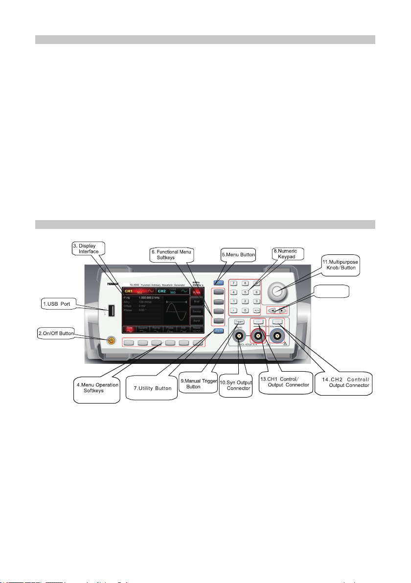
4. Menu Operation Softkeys
• These buttons are used to control the parameters of the currently active function.
5. Menu Button
•Press it and four functional labels appear: Wave, Mod, Sweep and Burst. To select
one of these functions press the functional menu softkey.
6. Functional Menu Softkeys
• Select or check the labels of softkeys (on the right of the display screen) via the
corresponding identification on the labels.
7. Utility Button
•Press the button for four functional labels: CH1 setting, CH2 setting, I/O (or freq
meter) and system and the highlighted label (central background in grey and
characters in pure white) all of which have their sub-labels on the bottom of the
display screen.
• These sub-labels can help you with what the highlighted label is related to.
• Press softkeys that correspond to sub-labels to enter specific setups or
information, to set up channels (e.g. set the output impedance within 1Ω-10kΩ
or to high impedance), to specify voltage limit, configure sync output, language,
power-on parameters, backlight, configuration of DHCP (dynamic host
configuration protocol) port, storage or recall, system information setting, help topic
lists etc.
8. Numeric Keypad
•Numeric keys from 0 to 9, decimal point “.” and symbol key “+/-”.
• The decimal point can be used to switch between units.
9. Manual Trigger Button
• Manual trigger is enabled when the backlight button flashes.
10. Sync Output Connector
•Synchronises signals to output all standard output functions (except DC and
noise).
11. Multi-purpose Knob/Button
•To modify a number or be used as directional buttons. Press the multi-purpose
knob to select functions or confirm the parameter that has been set.
12. Direction Buttons
• Switch between the numeric units or clear the digit prior to the current input or
move the cursor to the right or left, when using the multifunction knob and direction
key to set up parameters.
13 & 14. CH1/CH2 Buttons
• Use these buttons to quickly switch the current channel displayed on the screen.
•For example, if CH1 is highlighted, then channel 1 is the current chosen channel
and all displayed parameters are CH1 related.
• If the current channel is CH1 then you can press the CH1 button to turn on or off
the CH1 output quickly, or you can press UTILITY to enable the CH1 setting label
and then use the CH1 Setting softkey to adjust the settings.
•Under this status, the CH1 button backlight is illuminated and synchronously the
current output function mode shows up to the right of the CH1 label (“wave”, or
“Mod”, or “Sweep”, or “Impulse Train” icon) and CH1 connector output is enabled.
•With CH1 button switched off the button backlight turns off, the “Off” icon shows to
the right of the CH1 label and the CH1 connector is disabled.
• The above bullet points apply to CH2 also.

6
REAR PANEL
1. External Analogue Modulation Input Connector
•For AM, FM, PM or PWM modulation type, the terminal is used for the signal input
when external modulation source is selected.
•The corresponding modulation depth or deviation value (frequency, phase or duty
cycle) will be controlled by ±5V signal level present on this input terminal.
2. External Digital Modulation or Counter Connector
•For ASK, FSK or PSK modulation type, this connector is used for signal input
when the external source modulation is selected.
•Output amplitude, frequency and phase will be controlled by signal levels present
on this connector.
•For Sweep or Impulse Train mode, when you select external source as the trigger,
it is used to accept polarised TTL pulse that can enable the sweep or impulse train
with the specied cycle.
•If the impulse train is gated, you can input a gated signal via this connector.
• When using the frequency meter function you can also use the connector to
input signal (compatible with TTL level signal) or output trigger signal when under
Sweep or Impulse Train mode.
•When an external trigger source is selected, the Trigger Out option on the
parameter list will be ensconced, since this connector cannot be used for input and
output terminals at the same time.
3. LAN Connector
• Connect the Generator to the the local network for the remote control.
4. USB Connector
• Connect the Generator to a PC using the USB cable.
5. External 10MHz Input Connector
•Use this connector to input external 10MHz reference signal after the Generator’s
clock source is set up externally.
•To synchronize multiple 72-3555 generators or output 10MHz reference frequency
signal, use this external output connector.
6. Internal 10MHz Output Connector
• To output 10MHz reference signal after the Generator’s clock source is set up
internally.
10. AC Power
Receptacle
9.Master Power
Switch
4.USB Connector
1.External Analog
Modulation Input
2.
External Digital
Modulation or
Counter Connector

7
• When you want to synchronise multiple 72-3555 generators or output 10MHz
reference frequency signal, use this internal output connector.
7. Air Vent
•To ensure the Generator does not overheat, keep this vent uncovered.
8. Fuse
•To prevent damage to the Generator, the fuse will blow and disconnect the power
supply if the input AC current exceeds 2A.
9. Master Power Switch
•To energize the Generator when set to “I”, otherwise set to “O” to disconnect AC
input (On/Off button on the front panel will not work).
AC POWER RECEPTACLE
AC power specication for the Generator: 100 to 240V, 45 to 440Hz, power fuse: 250V,
T2 A.
Display Interface
CH1 and CH2 information
•When the display is highlighted (red for CH1 and blue for CH2), it indicates which
channel information is enabled and which channel parameters can be set up.
• Only the highlighted channel can have its parameters changed.
•For the respective channels’ display there is a “Limit” icon that represents
the output amplitude limit. The limit will either be white or grey, for on and off
respectively.
• The impedance value of the output terminal needs to match (adjustable within
1Ω~10kΩ, or set to high impedance, 50Ω by default).
• On the right of the display it shows the current effective waveform (waveform
shape, or “Mod”, “Sweep” or “Impulse Train” icon) or “Off” in grey for when the CH
output connector is switched off.
Softkey Labels
• These labels identify the current functions of the functional menus softkeys and

8
menu operation softkeys on the right and bottom of the display.
• The centre of the active label will be in the colour corresponding to that of the
current channel, or grey in system setting and the characters are white.
Labels on the right of the screen
• The labels will be highlighted when selected.
•The six softkey labels at the bottom of the screen will display options related to the
label on the right.
•Note: if the currently selected label has more than one sub-catalogue, the
displayed options on the bottom screen are not necessarily the sub-catalogues of
the label. For instance, if types of key label are highlighted, the sub-labels for types
of waveforms will be at the bottom of the screen, which are the sub-catalogue of
types of key label.
• If you press the Menu button, the wave label will be highlighted on the right,
however the labels at the bottom of the screen remain unchanged, though are not
sub-catalogues of Wave.
•When the label on the right includes more than six options, press the label again to
access the next screen to view more options.
Sub-labels at the bottom of the screen
•When sub-label options are from the Type menu, these labels will be highlighted
when active.
•When the sub-labels are from the Params menu or the Utility menu, the sub-label
options correspond with parameters and are also highlighted around the edges
with the same colour as that of the current channel, or grey when in the Utility
menu.
•Once a sub-label has been selected, rotating the multipurpose knob or pressing
the left and right buttons will cycle through the parameter that correspond to the
sub-label.
•Use the multipurpose knob if you want to modify the parameter, press the
multipurpose knob to begin editing the setting. Press the knob again when editing
is over.
•If “sub-label” has been selected instead of “editing” status, turning the
multipurpose knob or pressing the directional buttons along with the label,
enables the switch between different labels (switch between different parameters
accordingly in the parameter list).
•To modify parameters, you can enter the numbers directly using the numeric
keypad, with the left arrow button as a delete function in this mode.
• Select the desired unit using the softkeys options at the bottom of the screen to
confirm and exit editing.
Waveform Parameter List
• All parameters related to the current waveform will be listed on the screen.
• They can also be accessed by pressing the Params softkey on the right of the
screen.
•When the parameters are highlighted, it can be edited.
•To use the multipurpose knob, press it once and rotate it to increase or decrease
the number selected, using the left and right buttons to select different digits.

9
•Alternatively, the number required can be typed using the numerical keypad.
Waveform Display Zone
•No waveform displays when setting the system, so the waveform graphic zone are
expanded for the parameter list.
START
Adjusting the Carrying Handle
• The Generator is designed with a carrying handle.
•To adjust the handle, hold it by either side and pull outwards.
• The handle will then be able to be moved into the desired position.
Outputting Basic Waveforms
•Once powered on, the Generator congures a default sine wave with 100mVp-p
sine wave with a 0V DC offset, with a frequency of 1kHz (into a 50Ω terminal).
Setting Output Frequency
To change the frequency to 2.5MHz, follow the steps below:
• Press Menu→Wave→Params→Freq button or
softkey.
•When you change the frequency, the same
frequency is used if the current frequency value
is valid for the new application.
•To modify the waveform period at this moment,
press the Freq softkey again to toggle between
“Period” and “Freq” labels.
•Enter the desired number “2.5” using the numeric keypad.
Select the desired unit
• Press the softkey that corresponds with the desired unit.
•Once the unit is selected, the Generator outputs the waveform with the displayed
frequency (if the output has been enabled).
•In this example, press the MHz softkey.
Note: You can also use the multipurpose knob and direction buttons together to set
this parameter.
Setting Output Amplitude
To change the amplitude to 300mVpp, follow the steps below:
• Press Menu→Wave→Params→Amp button or
softkey.
•When you change the amplitude, the same
amplitude is used if the current amplitude value
is valid for the new application.
• Press the Amp softkey again to quickly switch
between different units (Vpp, Vrms and dBm).
•Enter the desired number “300” via the numeric
keypad.

10
SETTING DC OFFSET VOLTAGE
To change the amplitude to 300mVpp, follow the below steps:
• Press Menu→Wave→Params→DC offset button or softkey.
•When you change the DC offset, the same DC offset is used if the current DC
offset value is valid for the new application.
• Press the DC offset softkey again and you will
find the original waveform that is defined by the
amplitude and the DC offset will change into
the one using high level (Max) and low level
(Min).
•Enter the desired number “1150mV” using the
numeric keypad.
Select the desired unit
• Press the softkey that corresponds with the desired unit.
•Once the unit is selected, the Generator outputs the waveform with the displayed
DC offset.
•In this example, press the mV softkey.
Note: You can also use the multipurpose knob and direction buttons together to set
this parameter.
Select the desired unit
• Press the softkey that corresponds with the desired unit.
•Once the unit is selected, the Generator outputs the waveform with the displayed
frequency (if the output has been enabled).
•In this example, press the mVpp softkey.
Note: You can also use the multipurpose knob and direction buttons together to set
this parameter.
SETTING THE SQUARE WAVE
• The duty cycle of square wave represents the amount of time per cycle that
the square wave is at a high level (on the assumption that the waveform is not
inverted).
•Once powered on, the duty cycle of the square wave defaults at 50%.
• The duty cycle is limited by 20ns minimum pulse width.
•To set the frequency to 1kHz, amplitude 1.5Vpp, DC offset to 0V and duty cycle
to 70% for the square wave, follow the below
steps:
• Press Menu→Wave→Type→Square→
Params softkey.
•In order to set up the required parameters,
press the softkey that corresponds to the
parameter, then enter the desired value and
finally select the desired unit.
Note: You can also use the multipurpose knob and direction buttons together to
modify the parameters.

11
SETTING THE PULSE WAVEFORM
•The duty cycle of square wave represents the amount of time from 50% threshold
of rising edge to 50% threshold of next falling edge per cycle (on the assumption
that the waveform is not inverted).
•You can configure the generator to output a pulse waveform with a variable pulse
width and edge time.
•Once powered on, the duty cycle of pulse waveform is 50% and the rising/falling
edge time is 1µs by default.
•To set the period to 2ms, the amplitude to 1.5Vpp, DC offset to 0V, duty cycle
to 25%, rising edge time to 200µs and falling edge time to 200µs for the pulse
waveform, follow the steps below:
• Press Menu→Wave→Type→Pulse→Params button or softkey (if the Type label
is not highlighted, press the Type softkey again to select), then press Freq softkey
to switch from Frequency to Period.
• Then enter the period value and select the desired unit.
•To enter duty cycle value, press the softkey that corresponds to 25% on the bottom
of the screen to directly enter the number, or
you can also enter the number “25” and press
% to complete input.
•To set the falling edge time, press the Params
softkey again or turn the multipurpose knob
clockwise to access the next parameter page
and then press the TailEdge softkey and enter
the desired value and select the desired unit.
Note: You can also use the multipurpose knob
and direction buttons together to modify the parameters.
SETTING DC VOLTS
The DC waveform voltage varies with the current DC offset. Modifying DC offset will
change the default value of DC voltage (DC offset).
Once powered on, the DC voltage defaults at 0V.
To set DC voltage to 3V, follow the below steps:
• Press Menu→Wave→Type→DC. When you
change,DC Volts (DC offset) is used if the
current DC voltage (DC offset) is valid for the
new application.
•Enter the number “3” using the numeric
keypad.
Select the desired unit
• Press the softkey that corresponds with the desired unit.
•Once the unit is selected, the Generator outputs the waveform with the displayed
DC offset.
•In this example, press the Vsoftkey.
Note: You can also use the multipurpose knob and direction buttons together to
modify DC offset.

12
SETTING THE RAMP WAVEFORM
• Symmetry represents the amount of time per cycle when the ramp is positive.
•Once powered on, the ramp symmetry is 100% by default.
•To congure triangle waveform with the frequency set to 10kHz, the amplitude to
2V, DC offset to 0V and duty cycle to 50%, follow the steps as shown below.
• Press Menu→Wave→Type→Ramp→Params.
•To set the required parameters, press the
corresponding softkey at first and then enter
the desired value and the desired unit.
•When entering the symmetry value, you can
press the softkey corresponding to the 50%
label to directly input, or input “50” and press
“%” to complete the input.
Note: You can also use the multipurpose knob and direction buttons together to
modify the parameters.
SETTING THE NOISE WAVEFORM
The standard Gaussian noise has a 100mVpp amplitude and 0mV DC offset by default.
The default noise waveform also changes accordingly if the amplitude and DC offset
functions of other waveforms have been modied.
Only the amplitude and DC offset of the noise waveform are available to modify.
To set standard Gaussian noise amplitude to 300mVpp and DC offset to 1V, follow the
below steps:
• Press Menu→Wave→Type→Noise→Params.
•To set the required parameters, press the corresponding softkey and then enter
the desired value and the desired unit.
Note: You can also use the multipurpose knob and direction buttons together to
modify the parameters.
FREQUENCY MEASUREMENT
•The Generator can measure the frequency (ranging from 100MHz~200MHz) of
compatible TTL level signal and the duty cycle of it.
•When using the frequency meter function, compatible TTL level signal is input
through external digital modulation or through frequency meter port (FSK Trig/CNT
connector).
• By pressing Utility→Freq Meter to read, “frequency”, “cycle” and “duty cycle” can
be read out from the parameter list.
• The previously measured value is displayed in the parameter list as always when
there is no signal input.
• Frequency meter display refreshes only if compatible TTL level signal is input
through external digital modulation or frequency meter port.
USING THE BUILT-IN HELP SYSTEM
•The built-in help system offered by the Generator provide a context-sensitive
assistance on any front-panel button or menu softkey.
• The design of the help topics list also helps with some front-panel operations.

13
View help information of a function key
•Pressing any softkey for 3 seconds, for example, the Menu button, will display a
help message for that button.
• Press Return to exit the help function.
View help information of displayed messages
•The Generator will display a message whenever the limit is exceeded or any
conguration is not valid.
Local langauage help
•The built-in help system is available in English, simple Chinese and traditional
Chinese.
•All messages, context-sensitive help information and help topics are displayed in
the selected language.
•To select local language, press Utility→System→Language, then press the
arrow label softkey to select the desired language (or turn the multipurpose knob
to select).
ADVANCED APPLICATIONS
OUTPUTTING MODULATED WAVEFORMS
Amplitude Modulation (AM)
•In amplitude modulation, a modulated waveform consists of a carrier and
modulation shape.
• The carrier amplitude varies according to the changing amplitude of modulation
shape.
• CH1 and CH2 of the Generator can be modulated independently with modulation
types applied with the same or different modes.
Selecting AM
• Press Menu→Mod→Type→AM to enable the
AM function.
•With the AM function enabled, the Generator
will output the modulated waveform according
to current settings of modulation shape and the
carrier.
Selecting the Carrier
•The AM carrier shape can be: sine wave,
square wave, ramp or arbitrary waveform
(except DC). It is sine wave by default.
•When AM is selected, press Carrier to access
carrier waveforms to select interfaces.

14
Setting Carrier Frequency
• Carrier frequency ranges could be different and depend on different carrier waves
selected.
• The default is at 1kHz for all functions. See the table below for details:
•To set the carrier frequency, select the carrier waveform rst and then use the
multipurpose knob and direction buttons to set up the parameters or press
Params→Freq softkeys in turn, enter the desired frequency value and select the
desired unit to complete the input.
Selecting Modulation Source
• The Generator can select an internal or
external source for modulation. With AM
enabled, the modulation source defaults at
internal.
•To modify the parameter, switch on AM
interface first, then turn the multipurpose knob
or press Params→Source→External softkeys
to complete the change.
Internal Source
•When you select internal source, the modulation shape can be: sine, square, up
ramp, down ramp, arbitrary, noise.
•After AM is enabled, the modulation shape defaults at sine.
•To modify this parameter, switch on AM interface rst and then turn the
multipurpose knob or press Params→Shape softkey and select the waveform
desired.
- Square: 50% duty cycle
- Up ramp: 100% symmetry
- Down ramp: 0% symmetry
- Arbitrary: when arbitrary waveform is selected as the modulation shape, the
waveform is automatically sampled to limit wavelength to 1000 points.
- Noise: White Gaussian
External Source
•When you select the external source for modulation, the modulation shape and
modulation frequency items hide from the parameter list and the carrier is
modulated by an external waveform.
•Modulating depth is controlled by ±5V signal level on the external analogue
modulation connector (Modulation In) on the rear panel.
Carrier Wave Min. Value Max. Value
Sine 1µHz 25MHz
Square 1µHz 5MHz
Ramp 1µHz 400kHz
Pulse 500µHz 5MHz
Arbitrary 1µHz 5MHz

15
SETTING MODULATION SHAPE FREQUENCY
• Modulating frequency is available to set up when you select internal modulation
source.
•With AM enabled, the modulation frequency defaults at 100Hz. To change
the frequency, use the multipurpose knob and direction buttons or press
Params→ModFreq softkeys to select from 50kHz to 2MHz.
•If the source is chosen externally, modulation shape and frequency options won’t
show on the parameter list.
•In this case, the carrier is modulated by an external waveform at a frequency of
0Hz to 20kHz.
Setting Modulation Depth
•Modulating depth is expressed with a percentage and represents amplitude
variation.
•AM amplitude depth can be selectable from 0%~120%, the default value is 100%.
•When modulating depth is at 0%, the output amplitude is a constant value (half of
the set value of carrier amplitude).
•At 100%, the output amplitude varies according to the modulation shape. At
greater than 100%, the Generator will not output one exceeding ±5V Peak-Peak
voltage (into 50Ω terminal).
•To modify modulation depth, use the multipurpose knob and direction buttons or
press Params→Depth.
•When you select external source for the modulation, the output amplitude is also
controlled by ±5V signal level presented on the External Analogue Modulation
Input (Modulation In) Connector.
•For instance, if modulating depth in the parameter list has been set to 100% then
when the modulation signal is +5V, AM output is at the maximum amplitude; at -5V,
AM output will go down to the minimum amplitude.
Applications
•Firstly, enable AM mode of the Generator.
• To set a 200Hz sine wave from internal source as modulation signal with a square
wave (200mVpp, 45% duty cycle, 10kHz) as the carrier and modulating depth at
80%, follow the steps below:
1) Enabling AM function
• Press Menu→Mod→Type→AM to enable the
AM function.
•For example, modulation depth in the parameter list has been set to 100%,
when +5V external modulation signal is applied, AM output amplitude goes up to
maximum value; AM output amplitude goes down to the mimimum with external
signal applied at -5V.

16
2) Setting Modulation Signal Parameters
•With AM function enabled, use the
multipurpose knob and direction buttons
to complete the setup. You can also press
Params in AM interface to reveal the display as
shown right:
• To set the desired parameter press the
corresponding softkey, then enter in the desired
value and select the unit as required.
3) Setting Carrier Signal Parameters
• Press CarrierTypeSquare (if the Type label is
not highlighted, press Type softkey again) to
select the square wave as the carrier signal.
• Use the multipurpose knob and direction
buttons to complete the setup. You can press
Params in the interface above to pop up the
display (right):
•To set the desired parameter, press the
corresponding softkey and then enter in the
desired value and select the unit as required.

17
4) Setting Modulating Depth
•With the carrier parameters setup nished,
press the Return softkey to return to the
interface (right) and then set the modulating
depth.
• Use the multipurpose knob and direction
buttons to complete the setup. You can press
Params→Depth softkeys, then key in “80”
using the numeric keypad and press the %
softkey to finish the setting.
5) Enabling Channel Output
• Press CH1 button on the front panel to switch
on CH1 output or press Utility to open the
menu and press CH1 setting to enable the
output.
•With channel output enabled, the CH1 button
will illuminate and the “Off” icon in grey to
the right of “CH1” label will change to “Mod”
in yellow, indicating CH1 output has been
enabled.
• View AM modulated waveform with an
oscilloscope (right).
FREQUENCY MODULATION (FM)
•In FM, the modulated waveform consists of the carrier and modulation shape.
• The carrier frequency varies according to the change of amplitude in the
modulation shape.
• CH1 and CH2 of the Generator can be modulated independently with modulation
types applied with the same or different ones.
Selecting FM
• Press Menu→Mod→Type→FM to enable FM
function.
•With FM enabled already, the Generator will
output the modulated waveform according
to modulation shape currently set and the
modulated waveform output by the carrier wave.

18
Selecting the Carrier
•The FM carrier wave can be: sine, square,
ramp or arbitrary waveform (except DC). The
default is sine.
•When FM is selected, press Carrier to access
the carrier waveforms to select interface.
Setting Carrier Frequency
• Carrier frequency ranges could be different and depend on different carrier waves
selected. The default is at 1kHz for all functions.
• See the following table for details:
Carrier Wave Min. Value Max. Value
Sine 1µHz 25MHz
Square 1µHz 5MHz
Ramp 1µHz 400kHz
Pulse 500µHz 5MHz
Arbitrary 1µHz 5MHz
•To set the carrier frequency, select the carrier waveform rst and then use
multipurpose knob and direction buttons to set up the parameters or press
Params→Freq softkeys, enter the desired frequency value and select the desired
unit to complete the setting.
Selecting Modulation Source
•The Generator offers both internal and external
modulation source.
•With FM enabled, the modulation source
defaults at Internal.
•To modify the parameter, switch on the FM
interface rst, then turn the multipurpose knob
or press Params→Source→Ext softkeys to
modify.
Internal Source
When you select internal source, the modulation shape can be: sine, square, up ramp,
down ramp, arbitrary or noise. The default is sine.
After FM is enabled, the modulation shape defaults at sine. To modify the parameter,
switch on the FM interface, turn the multipurpose knob or press Params→Wave
softkeys to select.
•Square: 50% Duty Cycle
•UpRamp: 100% Symmetry
•DownRamp: 0% Symmetry
•Arbitrary: When arbitrary waveform is selected as the modulation shape, the
waveform is automatically sampled and limited to 1,000 points.
• Noise: White Gaussian

19
• Modulating frequency is available to set up when you select internal modulation
source.
•With FM enabled, the modulation frequency defaults at 100Hz. To change
the frequency, use the multipurpose knob and direction buttons or press
Params→ModFreq softkeys to select from 50kHz to 2MHz.
•If the source is chosen externally, modulation shape and frequency options won’t
show on the parameter list.
•In this case, the carrier is modulated by an external waveform at a frequency of
0Hz to 20kHz.
Setting Frequency Deviation
• Frequency deviation represents the deviation of the frequency of modulated
waveform from the carrier frequency.
•FM frequency deviation can be settable from 1μHz to a half of the maximum
frequency value of the current carrier. The default is 1kHz.
•To change the deviation, switch on FM interface, use the multipurpose knob and
direction buttons together or press Params→FreqDev to change the frequency
deviation.
•Frequency deviation ≤ carrier frequency. If you set a frequency deviation value
greater than carrier frequency, the Generator will automatically limit the deviation
to the maximum value allowed with the current carrier frequency.
•Frequency deviation + carrier frequency ≤ the maximum value allowed with the
current carrier frequency. If you set the frequency deviation to an invalid value, the
Generator will automatically limit the deviation to a maximum value allowed with
the current carrier frequency.
Applications
Set up the FM mode of the Generator. To set
a 2kHz square wave from internal source as
modulation signal with a sine wave (100mVpp) as
the carrier with frequency deviation of 5kHz, follow
the next steps:
External Source
•When you select external modulation source, modulation shape and modulation
frequency items will no longer show on the parameter list.
•FM frequency deviation is controlled by ±5V signal level present on the External
Analogue Modulation Input (Modulation In) connector on the rear panel.
•When the signal level is positive, the Generator will output a frequency greater
than the carrier frequency, or less than the carrier frequency if the signal level is
negative.
•External signal with lower level generates smaller deviation. For example, if the
frequency deviation in the parameter list is set to 1kHz, the external modulation
shape will be at +5V when FM output frequency equals Carrier Frequency +1kHz;
and at -5V the FM output frequency equals Carrier Frequency -1kHz.
SETTING MODULATION SHAPE FREQUENCY

20
Press Menu→Mod→Type→FM to switch on FM function.
Setting modulation signal parameters
•With FM interface enabled above, use the
multipurpose knob and direction buttons to
complete the setup.
• You can also press Params on the interface
above to reveal the display (right):
•To set the desired parameter, press the
corresponding softkey, then enter the desired
value and select the unit as required.
Setting Carrier Parameters
•Press Carrier→Type→Sine to select the sine
wave as the carrier signal. The default is sine,
so there is no need to modify.
• Use the multipurpose knob and direction
buttons to complete the setup, or you can press
the Params softkey in the interface to present
the display as shown right:
•To set the desired parameter, press the
corresponding softkey, then enter the desired
value and select the unit as required.
Table of contents
Other Tenma Portable Generator manuals