Figure-50
Figure-45
Figure-44
Figure-43
Figure-42
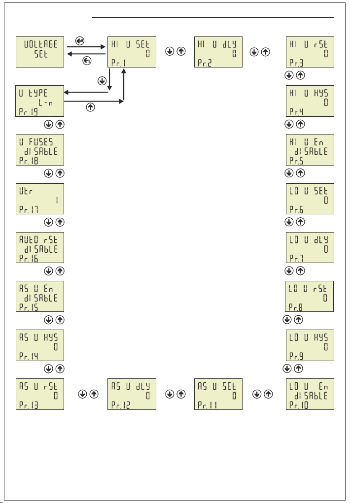
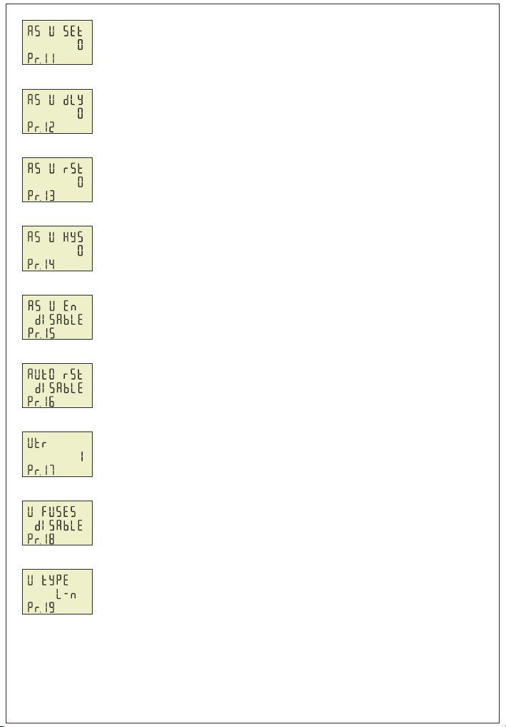
Pr.11: Voltage Asymmetry Protection Value : Determines the controlled voltage
asymmetry. Asymmetry Ratio Adjusment: Device calculates a value by dividing
difference between highest and lowest phase value to highest phase value.
Asymmetry Ratio = [(Highest Voltage – Lowest Voltage) / Highest Voltage ] x 100
Default: %20, Min: %5, Max: %30
Pr.16: Voltage Auto Reset Enable/Disable: If auto reset enable and system into error,
if all voltage are over/below the protect value as hysteresis value ,relay output switches
on at the end of the Reset time. If Auto reset is disable, after all voltage are over/below
hysteresis value, relay output switches manually. (Using ESC button).
Default: Enable, Min: Disable, Max: Enable
Pr.12: Voltage Asymmetry Protection Delay time: Determines delay open time. Delay
time for activating the output. If calculated asymmetry value below the voltage
asymmetry protect value, Relay output switches open at the end of delay time.
Default: 3sec, Min: 1sec, Max: 10000sec.
Pr.17: Voltage Transformer Ratio: If you use medium voltage , you can use VTR
Default: 1, Min: 1, Max: 999
Pr.13: Voltage Asymmetry Protection Reset Time: Determines delay close time.
If calculated asymmetry value over the voltage asymmetry protect value as a hysteresis
voltage , relay output switches close at the end of the reset time.
Default: 3sec, Min: 1sec, Max: 10000sec.
Pr.18: Voltage Fuses Enable/Disable: If any phase voltage exceeds 1.5 times of high
voltage protect values, or ,if any phase voltage decrease 0.5 times of low voltage protect
value, the relay switches off instantly. At position disable, voltage fuses function is
cancelled.
Default: Disable, Min: Disable, Max: Enable
Pr.14: Voltage Asymmetry Protection Hysteresis: Required hysteresis voltage for
voltage asymmetry warning is programmed.
Default: %2, Min: %1, Max: %10
Pr.19: Voltage Protection Type: Voltage Protection can be selected as L-N or L-L in
this menu. Phase-Neutral voltage protection can be implemented if the “L-N” protection
is selected. Phase-Phase voltage protection can be implemented if the “L-L” protection
is selected.
Default: L-n, Min: L-n, Max: L-L
Pr.15: Voltage Asymmetry Protection Enable/Disable: Determines Enable or Disable
the voltage asymmetry protection.
Default: Enable, Min: Disable, Max: Enable
Figure-46
Figure-47
Figure-48
Figure-49
-9-
Figure-71
Figure-70
Figure-69
Figure-68
Figure-67
Figure-66
Figure-65
Figure-61
Figure-60
Figure-59
V
Figure-58
Figure-56
A
Figure-55
Figure-54
A
Figure-52Figure-51
A
Figure-27
13.2 - Current Settings:
-10-
Pr.20: High Current Protection Value
Pr.21: High Current Protection Delay Time
Pr.22: High Current Protection Reset Time
Pr.23: High Current Protection Hysteresis
Pr.24: High Current Protection Enable/Disable
Pr.25: Low Current Protection Value
Pr.26: Low Current Protection Delay Time
Pr.27: Low Current Protection Reset Time
Pr.28: Low Current Protection Hysteresis
Pr.29: Low Current Protection Enable/Disable
Pr.30: Current Asymmetry Protection Value
Pr.31: Current Asymmetry Protection Delay Time
Pr.32: Current Asymmetry Protection Reset Time
Pr.33: Current Asymmetry Protection Hysteresis
Pr.34: Current Asymmetry Protection Enable/Disable
Pr.35: Current Auto Reset Enable/Disable
Pr.36: Current Transformer Ratio
Pr.37: Current Fuses Enable/Disable
Pr.38: Demurrage Protection Enable/Disable
Pr.39: Demurrage Protection Time
Pr.40: Demurrage Protection Factor
Set
Esc
Figure-53
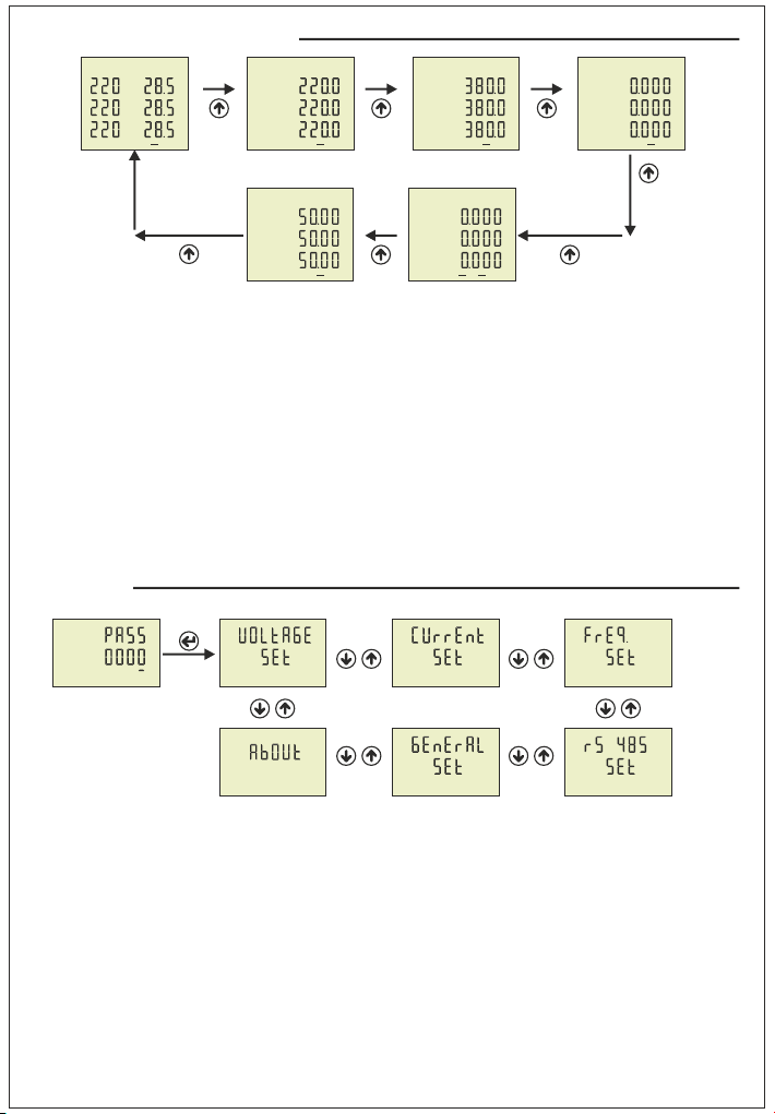
Press Menu button and enter password (Default Password =0000)
to enter program list. The figure-26(Voltage SET) is displayed when
you enter password and press the Menu button. The figure-27
(Current SET) is displayed when you press the up button. You enter
Current set when you press Menu button. If you enter Current set
menu, the figure-51(Pr.20) displayed. This menu have 21 different
current set value. When you press the up button to see the other
current set values on the display, the next data is displayed. The
figure-51 is displayed when you press the up button after the Pr.40
is displayed. By using up-down buttons select the program. Press
Menu to enter required program. By up-down buttons, you can set
the program. Press Menu to record your settings, if you press ESC
button, you cannot record your settings.
Figure-57
Figure-62Figure-64 Figure-63