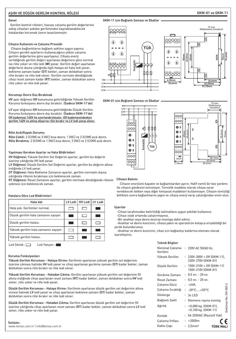
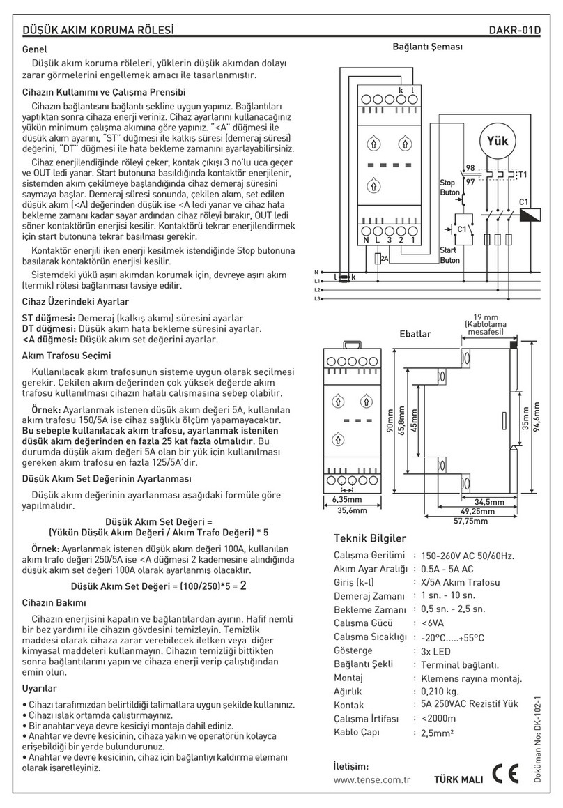
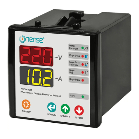
Tense RGM-12S User manual

RGM-12S
USER MANUAL
www.tense.com.tr
www.tenseenerji.com
ELEKTRİK - ELEKTRONİK SAN.TİC.A.Ş.

1
About RGM-12S
RGM-12S reactive power control relay is designed to reduce inductive powers not used by
loads but drawn from the network. If inductive reactive power is drawn from the network, it
intervenes by activating capacitors of appropriate value. In this way, it tries to bring the Cos fi
value to the desired level.
Index
1
1
About RGM-12S
8
Program (Intervention Logic) Change
10
9
Current Transformer Test
Determining the Step Count
11
Current Transformer Ratio
12
Step Measurement
13
Cosine Set Value
13
Cosine Tolerance Value
14
Step Drive Time
14
15
15
16
16
17
17
18
18
18
19
20
21
22
22
Step Release Time
Step Discharge Time
Over Compensation
Low Compensation
Harmonic Voltage
Harmonic Current
High Voltage
Blocking Access to Settings
Returning to Factory Settings
Fan and Alarm Output
Capacitor Calculation Table According to Connection Type
Factory Set Values
Dimensions
Technical Specifications
Contact Informations
11
Step Values
Considerations in Current Transformer Selection and Connection 3
3
4
5
6
7
Device Maintenance
Connection Diagram
Screen Introduction
Measurement Screens
Setting Screens
Matters to be Considered in Power Factor Correction
2
2
Features
Settings
Warnings
Easy to Install and Use with 20mm. 4 Digit Led Display
7 Different Compensation Programs
Manual Compensation Option
Can Only Compensate Inductive Systems
Automatic Step Measurement
Voltage and Current Harmonic Alarm Values Adjustable
Over and Under Compensation Alarm Values Can Be Set
Voltage, Harmonic Voltage/Current, Over and Under Compensation Alarm Output
Step Drive, Release and Discharge Times are Adjustable
Up to the 15th harmonic THD-I Can Be Monitored
Voltage, Current and Frequency Values Can Be Monitored
Active Power, Reactive Power and Apparent Power Values Can be Monitored
Up to the 15th harmonic THD-V Can Be Monitored
Cosine Value Can Be Monitored
Power Factor Value Can Be Monitored
Capacitive/Active and Inductive/Active Ratios Can Be Monitored
Automatic Fan Output
Step Values Can Be Monitored
Same Aging in Steps (In Certain Compensation Programs)
Features

1
About RGM-12S
RGM-12S reactive power control relay is designed to reduce inductive powers not used by
loads but drawn from the network. If inductive reactive power is drawn from the network, it
intervenes by activating capacitors of appropriate value. In this way, it tries to bring the Cos fi
value to the desired level.
Index
1
1
About RGM-12S
8
Program (Intervention Logic) Change
10
9
Current Transformer Test
Determining the Step Count
11
Current Transformer Ratio
12
Step Measurement
13
Cosine Set Value
13
Cosine Tolerance Value
14
Step Drive Time
14
15
15
16
16
17
17
18
18
18
19
20
21
22
22
Step Release Time
Step Discharge Time
Over Compensation
Low Compensation
Harmonic Voltage
Harmonic Current
High Voltage
Blocking Access to Settings
Returning to Factory Settings
Fan and Alarm Output
Capacitor Calculation Table According to Connection Type
Factory Set Values
Dimensions
Technical Specifications
Contact Informations
11
Step Values
Considerations in Current Transformer Selection and Connection 3
3
4
5
6
7
Device Maintenance
Connection Diagram
Screen Introduction
Measurement Screens
Setting Screens
Matters to be Considered in Power Factor Correction
2
2
Features
Settings
Warnings
Easy to Install and Use with 20mm. 4 Digit Led Display
7 Different Compensation Programs
Manual Compensation Option
Can Only Compensate Inductive Systems
Automatic Step Measurement
Voltage and Current Harmonic Alarm Values Adjustable
Over and Under Compensation Alarm Values Can Be Set
Voltage, Harmonic Voltage/Current, Over and Under Compensation Alarm Output
Step Drive, Release and Discharge Times are Adjustable
Up to the 15th harmonic THD-I Can Be Monitored
Voltage, Current and Frequency Values Can Be Monitored
Active Power, Reactive Power and Apparent Power Values Can be Monitored
Up to the 15th harmonic THD-V Can Be Monitored
Cosine Value Can Be Monitored
Power Factor Value Can Be Monitored
Capacitive/Active and Inductive/Active Ratios Can Be Monitored
Automatic Fan Output
Step Values Can Be Monitored
Same Aging in Steps (In Certain Compensation Programs)
Features

2
Make sure that there is no rapid load change in the system while performing current
transformer test and step measurement.
Compensation begins with the balanced arrangement of the load distribution in the electrical
installation of the system.
For the current transformer test, connect three phase capacitors in 1/40 (*) of the current
transformer value to the first two (C1 and C2) stages of the device.
( * : The total value of the first two steps.)
While preparing the compensation panel, make sure that new steps can be easily added for
changes that may occur later.
It is recommended to add new stages with the same value in terms of the lifetime of contactors
and capacitors in frequently used stages.
Matters to be Considered in Power Factor Correction
Select the fuse current values used in the steps according to the capacitor power
and mark the connection as a lifting element.
Use separate fuses for supply coils of step contactors.
Use compensation contactors and discharge coils in the steps.
Single phase connection in three phase systems is only suitable for balanced load draws.
Otherwise, the desired rates will not be achieved.
Warnings
Use the device in accordance with the instructions set by us.
After the device is mounted, leave a space of at least 10 cm. behind it.
Fix the device to the front cover of the panel with the accompanying apparatus.
Balance the inside and outside temperature in metal panels. Otherwise, water droplets are
formed on the ceiling of the panel due to the temperature difference in humid environments
and this is dangerous for open connected busbars.
Keep the switch and circuit breaker close to the device and within easy reach of the operator.
Mark the switch or circuit breaker as the disconnection element of the device.
Include a switch or circuit breaker in the assembly.
During installation, there should be no electricity in the connection cables.
Shielded and twisted cord cables should be used in input and output lines that are not
connected to the network. These cables should not be passed near high power lines and devices.
3
Maintenance of the Device
Power off the device and disconnect it from the connections. Clean the body of the device
with a slightly damp or dry cloth. Do not use conductors or other chemicals that could damage
the device as cleaning agents. After the device is cleaned, make its connections and make sure
that the device is powered and working.
Considerations in Current Transformer Selection and Connection
Make sure that the current transformer value is higher than the maximum current drawn
from the system.
It is recommended that the class of the current transformers to be used in compensation
systems should be 0.5.
Only X/5A current transformers can be connected to the RGM-12S.
Make sure that there is no load before the current transformers. Otherwise, there will be
differences in consumption and rates between the device and the electricity meter.
The current transformer must be connected to the phase from which the voltage input of the
device is received. Otherwise, the device will not be able to perform the current transformer test.
Current transformer output cables should not be close to the high voltage line.
It is recommended to use minimum 1.5mm² of cables to be connected to current transformer
output ends. As the distance gets longer, it is recommended to thicken the cable or to use a
current transformer with high output power.
Fix the current transformer to the busbar, cable or rail so that it does not shake.
The cable connected to the current transformer output ends should be made as one piece as
possible. Otherwise, there may be errors in the measurements and the current transformer
test may not be performed.

Single Phase Connection Diagram (L-N)
4
Pr2: Step Values (kVar) / Step Test
Pr5: Step Drive Time (sec)
Pr6: Step Release Time (sec)
Pr7: Step Discharge Time (sec)
Pr3: Cosine Set
Pr4: Cosine Tolerance (%)
Pr12: High Voltage Set (V)
Pr11: THD-I Set (%)
Pr10: THD-V Set (%)
Pr9: Low Compensation
Pr8: Over Compensation
Pr1: Current Transformer Ratio
Current (A)
P (kW)
Q (kVAr)
S (kVA)
Voltage (V)
PF
Q/P (%Ind)
-Q/P (%Cap)
F (Hz)
COS φ
THD-I (%)
THD-V (%)
5s
DOWN ESC
+
(C.T. TEST)
UP ESC
+
(STEP COUNT)
SET
UP
DOWN
ESC 5s
(MODE)
RGM-12S Monophase Power Factor Controller
FAN
5s
Screen Introduction
5
1
32
6
7
8
9
1- Step LEDs: These are the LEDs that light up when the steps are active.
5- Fan LED: It is the LED that lights up to inform the user when the fan output is active.
6- Alarm LED: It is the LED that lights up to warn the user in alarm situations.
2- LED Display: It is the screen where all measurements, settings and notifications regarding
the device are transferred to the user.
3- Status LEDs: Compensation status notification LEDs.
OVER: If the cosine value is above the overcompensation value, this LED turns on.
LOW: If the cosine value is below the undercompensation value, this LED turns on.
NORMAL: If the cosine value is between the over and under compensation values, this LED will light.
7- Buttons: They are used for monitoring measurements and making settings.
8- Measurments & Settings LEDs: Indicates that the device is in the measurement or setting menu.
9- Value & Parameter LEDs: When the device is in the measurement menu, it informs that the
measured value is displayed on the screen, and the parameter is displayed while in the setting menu.
4- Compensation Mode LED: Indicates the compensation mode of the device.
ESC Button: When pressed while in the menu, it returns to the upper menu without saving the
values. When pressed outside the menu (on the measurement screens) it always brings up the
Cosine measurement screen. When pressed for 5 seconds, Compensation Mode screen is entered.
SET Button: Enters the menu/parameter. If the parameter has been changed, it will save and
exit the parameter.
UP Button: Scrolls through measured values outside the menu. Switches between parameters
while in the menu. Increases the selected value while inside the parameters.
DOWN Button: Scrolls through measured values o utside the menu. Switches between parameters
while in the menu. Decreases the selected value while inside the parameters.
UP + ESC Button: Step Count screen is entered when these two buttons are pressed together for 5 sec.
DOWN + ESC Button: C.T. test screen is entered when these two buttons are pressed together for 5 sec.
4
5
N
L1
L2
L3
N
VoltageCurrent
2A
L
l1k1
Steps (1 to 7)
Harmonic Filter
Capacitor
Thermal
A2
2A
6A
A1
L C1 C2 C3 C4 C5 C6
Steps (8 to 12)
L C8 C9 C10C11C12
Harmonic Filter
Capacitor
Thermal
A2
2A
6A
A1
C7
Fan and Alarm Outputs
LFAN
6A
A2
2A
A1
ALR
Fan
A2
2A
A1
Alarm
Contactor
Contactor
Contactor
Contactor
To Load

Measurement Screens
6
8888-985
... . 8 8 8 83 5 0
.. . . 8 8 8 82 3 0
.. . .
Figure φ)-1 (Cos Figure-2 (Current (A)) Figure-3 (Voltage (V))
Figure-4 (F (Hz))Figure-12 (PF)
8 8 8 85 0
.. . .
8 8 8 87 9 2 9
.. . .
8 8 8 81 3 8 9
.. . .
8 8 8 88 0 5 0
.. . .
8 8 8 85
.. . .
88888
.. . .
88881 3
.. . .
88882
.. . .
88880850
... .
UP
DOWN
Figure-5 (P (kW))Figure-11 (THD-I (%))
Figure-6 (Q (kVAr))Figure-10 (THD-V (%))
Figure-7 (S (kVA))Figure-8 (-Q/P (%Cap))Figure-9 (Q/P (%Ind))
While on the measurement screen, the
"MEASUREMENTS" led on the device lights up.
While this LED is on, the values shown on the
screen are the values of the measurements. If you
move by pressing the down button while the
MEASUREMENTS led is on, the following
measurement values will be displayed
sequentially. Pressing the up button will display
the previous measurement parameter. While
showing these values, the led for the related
measurement value lights up.
Figure-1: It shows the cosine value.
Figure-2: It shows the current value.
Figure-3: It shows the voltage value.
Figure-4: It shows the frequency value.
Figure-5: It shows the active power value.
Figure-6: It shows the reactive power value.
Figure-7: It shows the apparent power value.
Figure-8: It shows the capacitive/active ratio (%)
value.
Figure-9: It shows the inductive/active ratio (%)
value.
Figure-10: It shows the THD-V (%) value.
Figure-11: It shows the THD-I (%) value.
Figure-12: It shows the power factor value.
DOWN
UP
DOWN
UP
DOWN
UP
DOWN
UP
UP
DOWN
UP
DOWN
UP
DOWN
UP
DOWN
UP
DOWN
UP
DOWN
UP
DOWN
7
8 8 8 8- 9 8 5
... .
Figure-1
Setting Screen
8 8 8 82 5 0 0
... . 8 8 8 80 9 4 0
... .
8 8 8 82 0
.. . .
8 8 8 80 0 1 0
... .
8 8 8 80 0 1 0
... .
8 8 8 81 0
.. . .
8 8 8 83 0
.. . .
8 8 8 82 5 0
.. . .
8 8 8 8- 9 8 5
.. . .
Figure-13 (Pr.1) Figure-14 (Pr.2) Figure-15 (Pr.3)
8 8 8 81 0
.. . .
Figure-16 (Pr.4)
Figure-24 (Pr.12)
8 8 8 83
.. . .
Figure-17 (Pr.5)
Figure-23 (Pr.11)
8 8 8 83
.. . .
Figure-18 (Pr.6)
Figure-22 (Pr.10)
Figure-19 (Pr.7)Figure-20 (Pr.8)Figure-21 (Pr.9)
In order to enter the setting screen, “SET”
button must be pressed for 2 seconds while in the
measurements screen. “SETTINGS” led on the
device lights up while on the setting screen. While
this LED is on, the values shown on the screen are
the values of the device settings. If you move by
pressing the down button while the SETTINGS led
is on, the values of the following setting
parameters will be displayed sequentially. While
showing these values, the led for the related
measurement value lights up. To change the value
of a parameter in the menu, enter the menu and
reach the relevant parameter with the help of up /
down buttons. Then press the SET button to enter
the relevant parameter, when you enter the
parameter, the led of the parameter will start to
blink. Then adjust the value you want with the up /
down buttons and press the SET button to save it.
The device will save the value and return to the
upper menu. After this process, the parameter led
will stop flashing and turn on steady.
Figure-13: Pr1: Current Transformer Ratio
Figure-14: Pr2: Step Values
Figure-15: Pr3: Cosine Set Value
Figure-16: Pr4: Cosine Tolerance Value
Figure-17: Pr5: Step Drive Time (sec.)
Figure-18: Pr6: Step Release Time (sec.)
Figure-19: Pr7: Step Discharge Time (sec.)
Figure-20: Pr8: Over Compensation Value
Figure-21: Pr9: Under Compensation Value
Figure-22: Pr10: THD-V Set Value (%)
Figure-23: Pr11: THD-I Set Value (%)
Figure-24: Pr12: High Voltage Set Value
8 8 8 81 0 0
... .
SET
The device shows the Cosine value on the measurements screen on the
left. While on any measurement screen, the SET button is pressed for 2
seconds in order to enter the menu.
(2sec.)
DOWN
UP
DOWN
UP
DOWN
UP
UP
DOWN
UP
DOWN
UP
DOWN
UP
DOWN
UP
DOWN
UP
DOWN
UP
DOWN
UP
DOWN
DOWN
UP

Settings EProgram (Intervention Logic) Change
8888Auto
.. . . Auto: It intervenes according to the step values. It activate the
required step. Works in accordance with same aging. While the device
is in this program, the "Auto" led turns on.
8
8888rot1
.. .. Rotation-1: In this mode, all steps must have the same value. It is
sufficient to measure only the 1st step in step measurement. It
automatically saves the next steps at the value of this step and
compensates accordingly. (For example: If the first step is 5kVAr, it
records all other steps as 5kVAr.) It works in accordance with same
aging. When the device is in this mode, the "Auto" led turns on.
8888rot2
.. .. Rotation-2: In this mode, the 2nd and subsequent steps must have
the same value and twice the value of the 1st step. It is sufficient to
measure only the 1st step in step measurement. It automatically
saves the next steps at 2 times the value of the 1st step and
compensates accordingly. (For example: If the first stage is 10kVAr, it
records all other steps as 20kVAr.) It works in accordance with same
aging. When the device is in this mode, the "Auto" led turns on.
8888rot3
.. .. Rotation-3: In this mode, the 2nd step should be 2 times the value of the 1st
step and the 3rd and next steps must be twice the value of the 2nd step. It is
sufficient to measure only the 1st step in step measurement. It automatically
saves the next steps according to the above rule and compensates accordingly.
(For example: If the 1st step is 5kVAr, it records the 2nd step as 10kVAr and all
the other stages as 20kVAr.) It works in accordance with same aging. When the
device is in this mode, the "Auto" led turns on.
Changing the Program: The device has 7 different compensation programs. The first 6 of these
modes operate automatically and when one of these modes is activated, the "AUTO" led on the
device turns on. The 7th mode is manual program and works in manual mode. When this mode is
active, the "MANUAL" led on the device lights up.
In order to change the program, when you press the "ESC" button for 5 seconds while on the
measurement screen (while MEASUREMENTS led is on), it enters the compensation program
selection screen and the default compensation program is displayed on the screen. While the
compensation program is displayed on the screen (auto, rot.1, rot.2, rot.3, rot.4, babb or noAt
(manual)), you can switch between programs with the Down and Up buttons. While the program you
want to select as a compensation program is displayed on the screen, you can save the selection by
pressing the SET button. After the compensation program selection is saved, the device returns to
the cosine screen and starts compensation according to the selected compensation program.
8888rot4
.. .. Rotation-4: In this mode, the 2nd step must be 2 times the 1st step,
the 3rd step must be 2 times the 2nd step, the 4th step and the next
steps must be 2 times the 3rd step. It is sufficient to measure only the
1st step in step measurement. It automatically saves the next steps
according to the above rule and compensates accordingly. (For
example: If the 1st level is 5kVAr, it records the 2nd step as 10kVAr,
the 3rd step as 20kVAr, the 4th step and all the other steps as
40kVAr.) It works in accordance with same aging. When the device is
in this mode, the "Auto" led turns on.
After the program selection,
the 1st step measurement
should be done.
!
After the program selection,
the 1st step measurement
should be done.
!
After the program selection,
the 1st step measurement
should be done.
!
After the program selection,
the 1st step measurement
should be done.
!
9
Settings EProgram (Intervention Logic) Change
Determining the Step Count to be Used: It determines with how
many steps the device will compensate. In order to determine the step
count to be used, while the device is on the measurement screen
(while MEASUREMENTS led is on). When you press the “ESC” and
“UP” buttons together for 5 seconds, it enters the step count
determination screen and the default step count (current setting of
the device) is displayed on the screen. With the DOWN and UP buttons
you can determine the step count to be used. While the step count to
be used is displayed on the screen, you can save the selection by
pressing the SET button or exit without saving by pressing the ESC
button. After the selection is saved, the device returns to the cosine
screen and starts compensation according to the selected step count.
For example: If you save by pressing the SET button while St.8 is
written on the screen, the device starts to compensate with only the
first 8 steps. It does not use other steps.
8 8 8 8b A b b
.. . . Start Over and Drop Mode: In this mode, steps should be at the lowest
value in the first step and at the highest value in the last step. (From small to
large value) Compensation is not made according to the step value,
therefore there is no need for step measurement. When the step is to be
activated, it always starts with the first step and activates the other steps one
by one. When the step is to be deactivated, it always starts with the first step
and deactivates the other steps one by one. It does not works in accordance
with same aging. When the device is in this mode, the "Auto" led turns on.
8 8 8 8n o A t
.. . . Manuel Mode: In this mode, the cosine value is displayed on the
screen. Each time the "UP" button is pressed, one step is activated,
starting from the first step. Whenever the "DOWN" button is pressed,
one step is deactivated sequentially, starting from the last activated
step. It does not works in accordance with same aging. When the
device is in this mode, the "Manuel" led turns on.
Note: When the manual mode is selected, if there are steps that are
activated, these steps are deactivated sequentially.
Not2: In this mode, the "ESC" button should be used to switch
between measurement screens.
8 8 8 8- 9 8 5
... .
8 8 8 8- 9 8 5
.. . .
8 8 8 8S t 1 2
.. . .
(5sec.)
8 8 8 8s t 8
.. . .
Settings EDetermining the Step Count
UP
ESC
+
UP
DOWN

Settings EProgram (Intervention Logic) Change
8888Auto
.. . . Auto: It intervenes according to the step values. It activate the
required step. Works in accordance with same aging. While the device
is in this program, the "Auto" led turns on.
8
8888rot1
.. .. Rotation-1: In this mode, all steps must have the same value. It is
sufficient to measure only the 1st step in step measurement. It
automatically saves the next steps at the value of this step and
compensates accordingly. (For example: If the first step is 5kVAr, it
records all other steps as 5kVAr.) It works in accordance with same
aging. When the device is in this mode, the "Auto" led turns on.
8888rot2
.. .. Rotation-2: In this mode, the 2nd and subsequent steps must have
the same value and twice the value of the 1st step. It is sufficient to
measure only the 1st step in step measurement. It automatically
saves the next steps at 2 times the value of the 1st step and
compensates accordingly. (For example: If the first stage is 10kVAr, it
records all other steps as 20kVAr.) It works in accordance with same
aging. When the device is in this mode, the "Auto" led turns on.
8888rot3
.. .. Rotation-3: In this mode, the 2nd step should be 2 times the value of the 1st
step and the 3rd and next steps must be twice the value of the 2nd step. It is
sufficient to measure only the 1st step in step measurement. It automatically
saves the next steps according to the above rule and compensates accordingly.
(For example: If the 1st step is 5kVAr, it records the 2nd step as 10kVAr and all
the other stages as 20kVAr.) It works in accordance with same aging. When the
device is in this mode, the "Auto" led turns on.
Changing the Program: The device has 7 different compensation programs. The first 6 of these
modes operate automatically and when one of these modes is activated, the "AUTO" led on the
device turns on. The 7th mode is manual program and works in manual mode. When this mode is
active, the "MANUAL" led on the device lights up.
In order to change the program, when you press the "ESC" button for 5 seconds while on the
measurement screen (while MEASUREMENTS led is on), it enters the compensation program
selection screen and the default compensation program is displayed on the screen. While the
compensation program is displayed on the screen (auto, rot.1, rot.2, rot.3, rot.4, babb or noAt
(manual)), you can switch between programs with the Down and Up buttons. While the program you
want to select as a compensation program is displayed on the screen, you can save the selection by
pressing the SET button. After the compensation program selection is saved, the device returns to
the cosine screen and starts compensation according to the selected compensation program.
8888rot4
.. .. Rotation-4: In this mode, the 2nd step must be 2 times the 1st step,
the 3rd step must be 2 times the 2nd step, the 4th step and the next
steps must be 2 times the 3rd step. It is sufficient to measure only the
1st step in step measurement. It automatically saves the next steps
according to the above rule and compensates accordingly. (For
example: If the 1st level is 5kVAr, it records the 2nd step as 10kVAr,
the 3rd step as 20kVAr, the 4th step and all the other steps as
40kVAr.) It works in accordance with same aging. When the device is
in this mode, the "Auto" led turns on.
After the program selection,
the 1st step measurement
should be done.
!
After the program selection,
the 1st step measurement
should be done.
!
After the program selection,
the 1st step measurement
should be done.
!
After the program selection,
the 1st step measurement
should be done.
!
9
Settings EProgram (Intervention Logic) Change
Determining the Step Count to be Used: It determines with how
many steps the device will compensate. In order to determine the step
count to be used, while the device is on the measurement screen
(while MEASUREMENTS led is on). When you press the “ESC” and
“UP” buttons together for 5 seconds, it enters the step count
determination screen and the default step count (current setting of
the device) is displayed on the screen. With the DOWN and UP buttons
you can determine the step count to be used. While the step count to
be used is displayed on the screen, you can save the selection by
pressing the SET button or exit without saving by pressing the ESC
button. After the selection is saved, the device returns to the cosine
screen and starts compensation according to the selected step count.
For example: If you save by pressing the SET button while St.8 is
written on the screen, the device starts to compensate with only the
first 8 steps. It does not use other steps.
8 8 8 8b A b b
.. . . Start Over and Drop Mode: In this mode, steps should be at the lowest
value in the first step and at the highest value in the last step. (From small to
large value) Compensation is not made according to the step value,
therefore there is no need for step measurement. When the step is to be
activated, it always starts with the first step and activates the other steps one
by one. When the step is to be deactivated, it always starts with the first step
and deactivates the other steps one by one. It does not works in accordance
with same aging. When the device is in this mode, the "Auto" led turns on.
8 8 8 8n o A t
.. . . Manuel Mode: In this mode, the cosine value is displayed on the
screen. Each time the "UP" button is pressed, one step is activated,
starting from the first step. Whenever the "DOWN" button is pressed,
one step is deactivated sequentially, starting from the last activated
step. It does not works in accordance with same aging. When the
device is in this mode, the "Manuel" led turns on.
Note: When the manual mode is selected, if there are steps that are
activated, these steps are deactivated sequentially.
Not2: In this mode, the "ESC" button should be used to switch
between measurement screens.
8 8 8 8- 9 8 5
... .
8 8 8 8- 9 8 5
.. . .
8 8 8 8S t 1 2
.. . .
(5sec.)
8 8 8 8s t 8
.. . .
Settings EDetermining the Step Count
UP
ESC
+
UP
DOWN

Settings ECurrent Transformer Test
8888-985
.. . .
8888truE
.. . .
8888tEst
.. . .
DOWNESC
+(5sec.)
Performing Current Transformer Test: For the current transformer
test, it is necessary to enter the Current Transformer Ratio first.
Please examine the section "Current Transformer Ratio" in the
manual to enter the current transformer ratio.
In order to make a current transformer test, when you press the "ESC"
and "DOWN" buttons together for 5 seconds while on the measurement
screen (while MEASUREMENTS led is on), "test" written will appear on
the screen. When you press the "SET" button, the device starts the
current transformer test. SETTINGS led and Pr1: Current Transformer
led turns on steadily. The device performs the current transformer
connection test by activating and deactivating the 1st and 2nd stages
respectively. If there is no problem in the connection (reverse connection
of current transformer k-l terminals is not important) "true" written is
displayed on the screen. Press the SET button to save the test and press
the ESC button to return to the previous menu without saving.
8888Err0
.. . .
8888Err1
.. . .
Err0 Error: If you get an "Err0" error in the current transformer
test, it means the voltage value that feeds the device is lower than
160V. Check the connections and perform a current transformer test
again after eliminating the error.
Err1 Error: If you get an "Err1" error in the current transformer
test, there may be a loose contact in the current transformer output
connections (s1 (k) and s2 (l). Check the connections and perform a
current transformer test again after eliminating the error.
8888Err3
.. . . Err3 Error: If you get an "Err3" error in the current transformer test, it
means there is an error in the current and voltage sequence. The phase to
which the current transformer is connected and the phase that feeds the
device may not be the same. In addition, fast load changes in the system,
defective contactors/capacitors, loose connections at the current
ends/steps outputs may also cause this error Check the connections and
perform current transformer test again after eliminating the error.
8888Err2
.. . . Err2 Error: If you get an "Err2" error in the current transformer test,
it means that the step current is insufficient. In order for the current
transformer test to be completed successfully, the total value of the
1st and 2nd step must be 1 in 40 of the current transformer value.
(For example: For a 50 / 5A current transformer, the total value of the
capacitors connected to the 1st and 2nd step must be at least 1.2kVAr
(three phase).)
For the Err2 error, please make sure that; The life of the capacitors
may be over, the capacitors may not be energized, the capacitor
feeding may have been taken before the current transformer, the
current transformer ratio may not be entered to the device.
10
Settings ECurrent Transformer Ratio
Entering Current Transformer Ratio: In order to change the
Current Transformer Ratio, press the “SET” button for 2 seconds
while on the measurement screen (while MEASUREMENTS led is on).
When you enter the setting menu, the MEASUREMENTS led will turn
off and the SETTINGS led will light up.
After entering the settings menu, the first parameter displayed on the
screen is Pr1: Current Transformer Ratio. While this parameter is
displayed on the screen, the led (Pr1: Current Transformer Ratio) of the
parameter also lights up steadily. To change the value of this parameter,
press the "SET" button and see that the led for the parameter is blinking.
When the parameter led is blinking, you can change the value of the
parameter by using the DOWN and UP buttons. After changing the
value of the parameter, press the SET button to save and press the
ESC button to return to the previous menu without saving.
When the changed parameter value is saved by pressing the SET
button, the device returns to the previous menu, the parameter value
is displayed on the screen and the parameter led does not blink, it
lights up steadily.
Example: If the Current Transformer Value is 100/5A, the ratio value
to be entered in Pr1 is "20". (100/5 = 20)
Monitoring Step Values: In order to see the step values that the
device measures automatically, press the “SET” button for 2 seconds
while on the measurement screen (while MEASUREMENTS led is on).
When you enter the setting menu, the MEASUREMENTS led will turn
off and the SETTINGS led will light up.
After entering the settings menu, the first parameter displayed on
the screen is Pr1: Current Transformer Ratio. Press the DOWN button
to access Pr2: Step Values parameter. To see the step values, press
the "SET" button and see that the led of the Pr2 parameter is blinking.
While the parameter led is blinking, you can see the step values by
using the DOWN and UP buttons. While the step value is displayed on
the screen, the information of which step this value belongs to is
associated with the step leds on the top of the screen. Press the
DOWN and UP buttons to switch between the step values and press
the ESC button to return to the previous menu.
NOTE: When entering this menu, the device deactivates the activated
steps one by one.
Settings EMonitoring Step Values
8 8 8 8- 9 8 5
... .
8 8 8 8- 9 8 5
.. . .
8 8 8 81
.. . .
SET (2sec.)
8 8 8 82 0
.. . .
8 8 8 8- 9 8 5
... .
8 8 8 8- 9 8 5
.. . .
8 8 8 80 5 0 0
... .
SET (2sec.)
8 8 8 82 5 0 0
... .
11
UP
DOWN
UP
DOWN

SettingsEStep Measurement
Making Automatic Step Measurement: In order to make an
automaticly step measurement, press the “SET” button for 2 seconds
while on the measurement screen (while MEASUREMENTS led is on).
When you enter the setting menu, the MEASUREMENTS led will turn
off and the SETTINGS led will light up.
After entering the settings menu, the first parameter displayed on
the screen is Pr1: Current Transformer Ratio. Press the DOWN button
to access Pr2: Step Values parameter. To see the step values, press
the "SET" button and see that the led of the Pr2 parameter is blinking.
8888-985
... .
8888-985
.. . .
88880500
... .
SET (2sec.)
8888-985
.. . .
8888st12
.. . .
8888All
.. . .
8888S t
.. . .
2 Measuring a Single Step: If you press the SET button while the step
value is on the screen, the device starts measuring the step for the
selected step. When step measurement is started, on the screen
shows the information for which step the measurement was made.
(For example: St.1 = means 1st step.) After the step measurement is
completed for the selected step, the step value is displayed on the
screen. Press the SET button to save the measured value, then exit
the menu by pressing the ESC button. Also, press the ESC button to
cancel the operation during the measurement and return to the
previous menu without saving the value after the measurement is
completed.
Measuring All Steps: To have all the steps measured, switch
between the steps by pressing the DOWN button. When you press the
DOWN button again after the 12th step, "ALL" will appear on the
display. When you press the SET button while the word "ALL" is
displayed on the screen, the device starts from the 1st step and
activates all the steps one by one and makes the step measurement.
After each step measurement, the measured value is displayed on the
screen for 2 seconds, and then the measurement is made for the next
step. After the measurement is completed for all steps, press the SET
button to save the measured step values, then exit the menu by
pressing the ESC button. Also, press the “ESC” button to cancel the
operation during the measurement and return to the previous menu
without saving the value after the measurement is completed.
NOTE: The lowest capacitor value that can be connected to a step is
90 VAR and the highest is 250 kVAR.
NOTE: When entering this menu, the device deactivates the activated
steps one by one.
12
UP
DOWN
UP
DOWN
SettingsECosine Set Value
Adjusting the Cosine Set Value: The target cosine set value for
compensation is set with this parameter. In order to change the cosine
value, press the “SET” button for 2 seconds while on the measurement
screen (while MEASUREMENTS led is on). When you enter the setting
menu, the MEASUREMENTS led will turn off and the SETTINGS led will
light up.
After entering the settings menu, the first parameter displayed on the
screen is Pr1: Current Transformer Ratio. Press the DOWN button to
access Pr3: Cosine Set p arameter. To see the parameter value, press
the "SET" button and see that the led of the Pr3 parameter is blinking.
When the parameter led is blinking, you can change the value of the
parameter by using the DOWN and UP buttons. After changing the
value of the parameter, press the SET button to save and press the ESC
button to return to the previous menu without saving.
When the changed parameter value is saved by pressing the SET
button, the device returns to the previous menu, the parameter value is
displayed on the screen and the parameter led does not blink, it lights
up steadily.
8 8 8 8- 9 8 5
... .
8 8 8 8- 9 8 5
.. . .
8 8 8 80 9 5 0
... .
SET (2sec.)
8 8 8 80 9 6 0
... .
13
SettingsECosine Tolerance Value
Adjusting the Cosine Tolerance Value: It is the movement area that will be
given to the device in inductive and capacitive directions in order to ensure less
on/off in order to extend the life of contactors, capacitors and reactors in the
steps. The device will not change its current intervention for reactive power
changes within the Cosine SET Value ± Cosine Tolerance Value area.
In order to change the cosine tolerance value, press the “SET” button for 2
seconds while on the measurement screen (while MEASUREMENTS led is
on). When you enter the setting menu, the MEASUREMENTS led will turn off
and the SETTINGS led will light up.
After entering the settings menu, the first parameter displayed on the
screen is Pr1: Current Transformer Ratio. Press the DOWN button to access
Pr4: Cosine Tolerance p arameter. To see the parameter value, press the
"SET" button and see that the led of the Pr4 parameter is blinking.
When the parameter led is blinking, you can change the value of the
parameter by using the DOWN and UP buttons. After changing the
value of the parameter, press the SET button to save and press the ESC
button to return to the previous menu without saving.
When the changed parameter value is saved by pressing the SET
button, the device returns to the previous menu, the parameter value is
displayed on the screen and the parameter led does not blink, it lights
up steadily.
Example: If the SET value is 0.940 and the tolerance value is ± 10, the device
will not change its current intervention for reactive power changes between
the cosine value of 0.930 and 0.950. If it is out of this value, the device
continues its intervention if there is an appropriate step value in the system
according to the drawn reactive power.
8 8 8 8- 9 8 5
... .
8 8 8 8- 9 8 5
.. . .
8 8 8 81 0
.. . .
SET (2sn.)
8 8 8 81 5
.. . .
UP
DOWN
UP
DOWN

14
SettingsEStep Drive Time
Adjusting the Step Drive Time: It determines the step drive
(activation) time to intervene in the power change in the system. In
order to change this value, press the “SET” button for 2 seconds while
on the measurement screen (while MEASUREMENTS led is on). When
you enter the setting menu, the MEASUREMENTS led will turn off and
the SETTINGS led will light up.
After entering the settings menu, the first parameter displayed on the
screen is Pr1: Current Transformer Ratio. Press the DOWN button to
access Pr5: Step Drive Time p arameter. To see the parameter value,
press the "SET" button and see that the led of the Pr5 parameter is
blinking.
When the parameter led is blinking, you can change the value of the
parameter by using the DOWN and UP buttons. After changing the
value of the parameter, press the SET button to save and press the ESC
button to return to the previous menu without saving.
When the changed parameter value is saved by pressing the SET
button, the device returns to the previous menu, the parameter value is
displayed on the screen and the parameter led does not blink, it lights
up steadily.
8888-985
... .
8888-985
.. . .
88883
.. . .
SET (2sec.)
88885
.. . .
SettingsEStep Release Time
Adjusting the Step Release Time: It determines the time to release
the active step in order to intervene in the power change in the system.
In order to change this value, press the “SET” button for 2 seconds
while on the measurement screen (while MEASUREMENTS led is on).
When you enter the setting menu, the MEASUREMENTS led will turn off
and the SETTINGS led will light up.
After entering the settings menu, the first parameter displayed on the
screen is Pr1: Current Transformer Ratio. Press the DOWN button to
access Pr6: Step Release Time p arameter. To see the parameter value,
press the "SET" button and see that the led of the Pr6 parameter is
blinking.
When the parameter led is blinking, you can change the value of the
parameter by using the DOWN and UP buttons. After changing the
value of the parameter, press the SET button to save and press the ESC
button to return to the previous menu without saving.
When the changed parameter value is saved by pressing the SET
button, the device returns to the previous menu, the parameter value is
displayed on the screen and the parameter led does not blink, it lights
up steadily.
8888-985
... .
8888-985
.. . .
88883
.. . .
SET (2sec.)
88885
.. . .
UP
DOWN
UP
DOWN
SettingsEStep Discharge Time
Adjusting the Step Discharge Time: It determines the capacitor
discharge (reactivate the same step) time. In order to change this value,
press the “SET” button for 2 seconds while on the measurement screen
(while MEASUREMENTS led is on). When you enter the setting menu,
the MEASUREMENTS led will turn off and the SETTINGS led will light
up.
After entering the settings menu, the first parameter displayed on the
screen is Pr1: Current Transformer Ratio. Press the DOWN button to
access Pr7: Step Discharge Time p arameter. To see the parameter
value, press the "SET" button and see that the led of the Pr7 parameter
is blinking.
When the parameter led is blinking, you can change the value of the
parameter by using the DOWN and UP buttons. After changing the
value of the parameter, press the SET button to save and press the ESC
button to return to the previous menu without saving.
When the changed parameter value is saved by pressing the SET
button, the device returns to the previous menu, the parameter value is
displayed on the screen and the parameter led does not blink, it lights
up steadily.
8 8 8 8- 9 8 5
... .
8 8 8 8- 9 8 5
.. . .
8 8 8 82 0
.. . .
SET (2sec.)
8 8 8 82 5
.. . .
15
SettingsEOver Compensation
Adjusting the Over Compensation Value: In case the Cosine value stays
above the Over Compensation Value for 3 minutes although the device
disables all steps, it enters an overcompensation error, the alarm relay is
energized, the OVER led flashes while the alarm and SETTINGS leds are
constantly lit. When the cosine value returns to the normal level for 10
seconds, the device disables the overcompensation error, the alarm relay is
deactivated, the alarm and OVER led turn off, the cosine led turns on.
In order to change this value, press the “SET” button for 2 seconds while
on the measurement screen (while MEASUREMENTS led is on). When you
enter the setting menu, the MEASUREMENTS led will turn off and the
SETTINGS led will light up.
After entering the settings menu, the first parameter displayed on the
screen is Pr1: Current Transformer Ratio. Press the DOWN button to
access Pr8: Over Compensation p arameter. To see the parameter value,
press the "SET" button and see that the led of the Pr8 parameter is blinking.
When the parameter led is blinking, you can change the value of the
parameter by using the DOWN and UP buttons. After changing the value of
the parameter, press the SET button to save and press the ESC button to
return to the previous menu without saving.
8 8 8 8- 9 8 5
... .
8 8 8 8- 9 8 5
.. . .
8 8 8 80 0 1 0
... .
SET (2sec.)
8 8 8 80 0 1 5
... .
When the changed parameter value is saved by pressing the SET button, the device returns to the previous
menu, the parameter value is displayed on the screen and the parameter led does not blink, it lights up steadily.
Example: Let Cosine set: 0.940, Cosine tolerance: 10 and overcompensation: 10. If the cosine value
stays above 0.960 for 3 minutes even though it deactivates all steps, this error occurs. If the cosine
value goes below 0.950 for 10 seconds after the error, the error situation will disappear.
NOTE: This feature is disabled in manual mode.
UP
DOWN
UP
DOWN

16
SettingsELow Compensation
Adjusting the Low Compensation Value: In case the Cosine value
stays under the Low Compensation Value for 3 minutes although the
device activates all steps, it enters an undercompensation error, the
alarm relay is energized, the LOW led flashes while the alarm and
SETTINGS leds are constantly lit. When the cosine value returns to the
normal level for 10 seconds, the device disables the
undercompensation error, the alarm relay is deactivated, the alarm
and LOW led turn off, the cosine led turns on.
After entering the settings menu, the first parameter displayed on the
screen is Pr1: Current Transformer Ratio. Press the DOWN button to access
Pr9: Low Compensation Time p arameter. To see the parameter value, press
the "SET" button and see that the led of the Pr9 parameter is blinking.
When the parameter led is blinking, you can change the value of the
parameter by using the DOWN and UP buttons. After changing the value
of the parameter, press the SET button to save and press the ESC button
to return to the previous menu without saving.
When the changed parameter value is saved by pressing the SET button, the device
returns to the previous menu, the parameter value is displayed on the screen and the
parameter led does not blink, it lights up steadily. When the changed parameter value is
saved by pressing the SET button, the device returns to the previous menu, the parameter
value is displayed on the screen and the parameter led does not blink, it lights up steadily.
8888-985
... .
8888-985
.. . .
88880010
... .
SET (2sec.)
88880015
... .
SettingsEHarmonic Voltage
Adjusting the THD-V Value: If the Total Harmonic Distortion Voltage
(THD-V) value stays above the THD-V Set value for 15 seconds, the
device enters a THD-V error, it stops compensation, the alarm relay
isenergized (it deacitivates all steps), the alarm led turns on and the
THDV led (Pr10: THD -V Set) flashes. When the THD-V value stays
below 3% of the THD-V set value for 15 seconds, the device disables
the THD-V error, the alarm relay is deenergized, the alarm and THD-V
led (Pr10: THD-V Set) turns off, the Cosine led turns on. The device
restarts compensation.
After entering the settings menu, the first parameter displayed on
the screen is Pr1: Current Transformer Ratio. Press the DOWN button
to access Pr10: TDH-V Set parameter. To see the parameter value,
press the "SET" button and see that the led of the Pr10 parameter is
blinking.
When the parameter led is blinking, you can change the value of the
parameter by using the DOWN and UP buttons. After changing the
value of the parameter, press the SET button to save and press the
ESC button to return to the previous menu without saving.
When the changed parameter value is saved by pressing the SET
button, the device returns to the previous menu, the parameter value
is displayed on the screen and the parameter led does not blink, it
lights up steadily.
8888-985
... .
8888-985
.. . .
88881 0
.. . .
SET (2sec.)
88881 5
.. . .
Example: Let Cosine set: 0.940, Cosine tolerance: 10 and low compensation: 10. If the cosine value stays
under 0.920 for 3 minutes even though it activates all steps, this error occurs. If the cosine value goes
above 0.930 for 10 seconds after the error, the error situation will disappear.
NOTE: This feature is disabled in manual mode.
UP
DOWN
UP
DOWN
17
SettingsEHarmonic Current
Adjusting the THD-I Value: If the Total Harmonic Distortion Current
(THD-I) value stays above the THD-I Set value for 120 seconds, the
device enters a THD-I error, it stops compensation, the alarm relay
isenergized (it deacitivates all steps), the alarm led turns on and the
THDI led (Pr11: THD-I Set) flashes. When the THD-I value stays below
5% of the THD-I set value for 60 seconds, the device disables the THD-
I error, the alarm relay is deenergized, the alarm and THD-I led (Pr11:
THD-I Set) turns off, the Cosine led turns on. The device restarts
compensation.
After entering the settings menu, the first parameter displayed on
the screen is Pr1: Current Transformer Ratio. Press the DOWN button
to access Pr11: TDH-I Set parameter. To see the parameter value,
press the "SET" button and see that the led of the Pr11 parameter is
blinking.
When the parameter led is blinking, you can change the value of the
parameter by using the DOWN and UP buttons. After changing the
value of the parameter, press the SET button to save and press the
ESC button to return to the previous menu without saving.
When the changed parameter value is saved by pressing the SET
button, the device returns to the previous menu, the parameter value
is displayed on the screen and the parameter led does not blink, it
lights up steadily.
8 8 8 8- 9 8 5
... .
8 8 8 8- 9 8 5
.. . .
8 8 8 83 0
.. . .
SET (2sec.)
8 8 8 83 5
.. . .
SettingsEHigh Voltage
Adjusting the High Voltage Value: If the Voltage value stays above
the High Voltage Set value for 5 seconds, the device enters a High
Voltage error, it stops compensation, the alarm relay isenergized (it
deacitivates all steps), the alarm led turns on and the High Voltage led
(Pr12: High Voltage) flashes. When the Voltage value stays below 10V
of the High Voltage set value for 5 seconds, the device disables the
High Voltage error, the alarm relay is deenergized, the alarm and
High Voltage led (Pr12: High Voltage) turns off, the Cosine led turns
on. The device restarts compensation.
After entering the settings menu, the first parameter displayed on
the screen is Pr1: Current Transformer Ratio. Press the DOWN button
to access Pr12: High Voltage parameter. To see the parameter value,
press the "SET" button and see that the led of the Pr12 parameter is
blinking.
When the parameter led is blinking, you can change the value of the
parameter by using the DOWN and UP buttons. After changing the
value of the parameter, press the SET button to save and press the
ESC button to return to the previous menu without saving.
When the changed parameter value is saved by pressing the SET
button, the device returns to the previous menu, the parameter value
is displayed on the screen and the parameter led does not blink, it
lights up steadily.
8 8 8 8- 9 8 5
... .
8 8 8 8- 9 8 5
.. . .
8 8 8 83 0
.. . .
SET (2sec.)
8 8 8 83 5
.. . .
UP
DOWN
UP
DOWN

Fan Output
Alarm Output
If any step remains active for 10 seconds, the fan output becomes energized. 1 minute after
all steps are deactivated, the fan output becomes deenergized.
Alarm output is energized in case of over compensation, undercompensation, high voltage,
THD-I and THD-V error conditions. After these error conditions are eliminated, the alarm
output is deenergized. Error entering delay and exit delay values are defined separately for
each error parameter. The alarm output relay and the alarm led work synchronously.
Settings EBlocking Access to Settings
Blocking Access to Settings: You can use this feature to block the
device's settings from being changed by unauthorized personnel.
To activate the feature: To activate this feature, press the “ESC” and
“SET” buttons for 5 seconds while on the measurement screen (while
MEASUREMENTS led is on). The word “b.oFF” appears on the screen
and the feature is activated. When this feature is active, it is not
possible to enter the setting menu.
To disable the feature: To disable this feature, press the “ESC” and
“SET” buttons for 5 seconds while on the measurement screen (while
MEASUREMENTS led is on). “B. on ”will appear and the feature will be
inactive. When this feature is disabled, it is possible to enter the
setting menu.
8888-985
... .
8888-985
.. . .
8888boff
... .
SETESC
+(5sec.)
Settings EReturning to Factory Settings
Returning to Factory Settings: In order to return the factory settings,
press the “SET” button for 2 seconds while on the measurement screen
(while MEASUREMENTS led is on). When you enter the setting menu,
the MEASUREMENTS led will turn off and the SETTINGS led will light up.
After entering the settings menu, the first parameter displayed on the
screen is Pr1: Current Transformer Ratio. Press the DOWN button to
access Pr12: High Voltage Set p arameter. Press the "ESC" and "UP"
buttons for 5 seconds while the led of the the Pr12 parameter is on
steady. "RSt" word will appear on the screen for 2 seconds and the
device will be back to factory settings. The device then returns to the
measurements screen.
Note: Returning to factory settings requires a re-setup of the device!
(All values a nd records such as current transformer value, step values,
menu settings, etc. will be reset.)
8888-985
... .
8888-985
.. . .
8888270
.. . .
SET (2sec.)
8888rst
.. . .
(5sec.)
UPESC
+
18 19
Capacitor Calculation Table According to Connection Type
0,5 KVAR
1 KVAR
1,5 KVAR
2,5 KVAR
5 KVAR
7,5 KVAR
10 KVAR
15 KVAR
20 KVAR
25 KVAR
30 KVAR
3 Phase
Connection
(Q/3)
Capacitor
Powers
0,16 KVAR
0,33 KVAR
0,5 KVAR
0,83 KVAR
1,66 KVAR
2,5 KVAR
3,33 KVAR
5 KVAR
6,66 KVAR
8,33 KVAR
10 KVAR
RST
Phase-Netural
Connection
(Q/6)
0,08 KVAR
0,16 KVAR
0,25 KVAR
0,41 KVAR
0,83 KVAR
1,25 KVAR
1,66 KVAR
2,5 KVAR
3,33 KVAR
4,16 KVAR
5 KVAR
SN
Table of contents
Other Tense Relay manuals
