Teo 6220-TSG-DD User manual
13-280121 Rev. C
February 2014
Teo Technologies, Inc.
11609 49th Place West
Mukilteo, WA 98275-4255
(800) 524-0024 (425) 349-1000
Fax (425) 349-1010
www.teotech.com
Tone Commander
6220-TSG-DD
ISDN Telephone
Installation
Instructions

Tone Commander 6220-TSG-DD Installation Instructions
Page 2 13-280121 Rev. C
© 2014, Teo Technologies, Inc. All rights reserved.
Teo and Tone Commander are registered trademarks of Teo Technologies, Inc.

13-280121 Rev. C Page 3
Contents
Introduction .....................................................................................................................................................5
General Features ..........................................................................................................................................5
Models/Options .............................................................................................................................................5
Controls and Indicators .................................................................................................................................7
Installation .......................................................................................................................................................9
Ordering ISDN Service..................................................................................................................................9
S/T Version (6220T-TSG-DD) Installation ....................................................................................................9
U Version (6220U-TSG-DD) Installation .....................................................................................................12
Line and Power Connections ......................................................................................................................12
Wall Mounting..............................................................................................................................................14
Configure the Set ........................................................................................................................................15
Label the Set ...............................................................................................................................................16
Installation Options ......................................................................................................................................17
Installation Options Menu............................................................................................................................17
SPID Entry...................................................................................................................................................18
Parameter Download (National ISDN only) ...............................................................................................18
Configuring Keys and Indicators .................................................................................................................19
Terminal Mode (National ISDN only) .........................................................................................................24
Installation Password ..................................................................................................................................25
Reset to Factory Default Settings ...............................................................................................................26
Administration Options ................................................................................................................................27
Administration Options Menu ......................................................................................................................27
Local Inspect ...............................................................................................................................................27
Version ........................................................................................................................................................30
Test..............................................................................................................................................................31
Diagnostic Display.......................................................................................................................................33
Restart .........................................................................................................................................................33
Viewing the Error and Download Logs........................................................................................................33
Troubleshooting............................................................................................................................................35
Inoperable Telephone Recovery Procedures .............................................................................................35
Telephone Configuration Troubleshooting..................................................................................................36
Appendix A Ordering ISDN Service ..........................................................................................................37
Recommended Button Assignments...........................................................................................................38
Appendix B Setup Menu Tree ...................................................................................................................39
Appendix C Warranty and Service ............................................................................................................43
Appendix D Specifications.........................................................................................................................44
Factory Default Settings ..............................................................................................................................45
Appendix E UL/FCC Statements ..............................................................................................................46

Tone Commander 6220-TSG-DD Installation Instructions
Page 4 13-280121 Rev. C

13-280121 Rev. C Page 5
Introduction
For operation instructions and user setup options, please refer
to the 6220-TSG-DD User Guide, doc. #14-280193.
General Features _____________________________________________
Tone Commander 6220-TSG-DD ISDN Telephones are easy to use multiline terminals with advanced
automatic setup capabilities. These models have been TSG-6 certified by the National Telecommunications
Security Working Group (NTSWG) to ensure on-hook security measures. In addition, the speakerphone
circuitry has been removed and all automatic call origination and answering functions have been disabled.
The phones do not provide voice encryption on an active call.
S/T and U interface models are available with 20 call appearances. An external NT1 Network Termination,
such as the Tone Commander NT1B-300TC, is required for S/T models. The phones support Lucent 5ESS
Custom ISDN and National ISDN on a variety of network platforms (see page 44).
Features of the 6220T-TSG-DD include:
•TSG-6 Certified for use in SCIF areas •Call Directory
•
AutoSPID and Parameter Download
•
Automatic Switch Type Detection
•
Call Log
•
Message Waiting Indication
•
Call Timer
•
Flexible Ringing Options
•Last Number Redial •Ringing Control for Shared Lines
•Speed Dial •Desktop or Wall Mounting
•Direct Station Select •Tilt Display
Models/Options ______________________________________________
Two telephone models are available; they differ in the type of ISDN connection. Models are identified on
the bar code/serial number label on the bottom of the phone.
The 6220T-TSG-DD model requires an external NT1 Network Termination, such as the Tone Commander
NT1B-300TC. Two S/T telephones can share a single ISDN line in a multi-point arrangement.
The 6220U-TSG-DD model includes a built-in NT1, allowing direct connection to the ISDN line without an
external NT1.
Options include the 6030X Button Expansion Module, which adds 30 multifunction keys, and the 6002TA
Analog Port Terminal Adapter for interfacing with an analog telephone device, such as an STU-III
telephone.
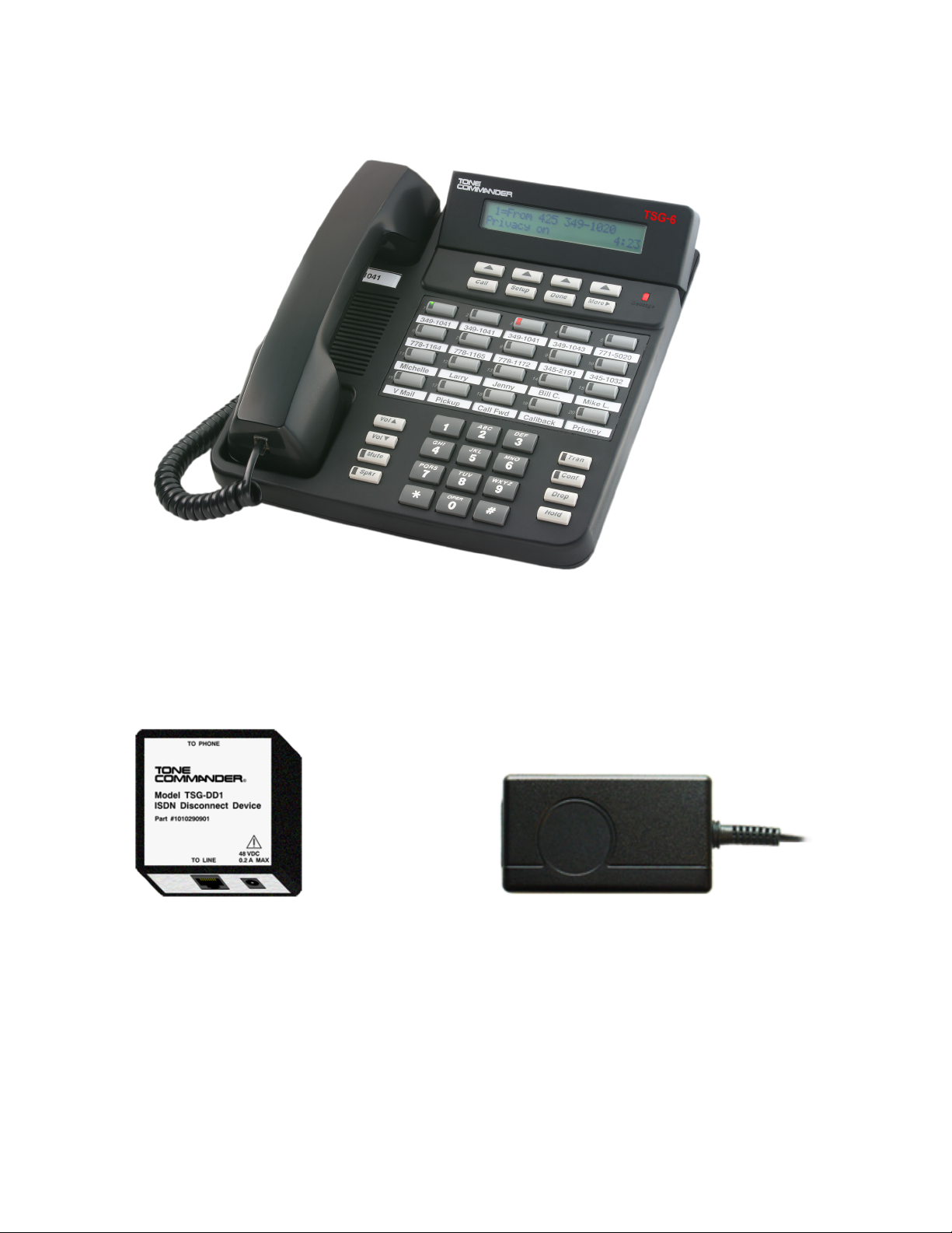
Both models are supplied with the TSG-DD1 Disconnect Device, which completely disconnects the ISDN
line from the phone when power is not applied, and a -PWR1 Desktop Power Supply.
TSG-6 Certification Numbers
6220T-TSG-DD .................. TSG-5S0605-2TC
6220U-TSG-DD .................. TSG-5S0605-1TC
Tone Commander 6220-TSG-DD Installation Instructions
Page 6 13-280121 Rev. C
6220T-TSG-DD/6220U-TSG-DD On-hook Secure ISDN Telephone
TSG-DD1 Disconnect Device -PWR1 Desktop Power Supply
Introduction
13-280121 Rev. C Page 7
Controls and Indicators _______________________________________
Call Setup Done More
Message
Tran
Conf
Drop
Hold
Vol
Vol
Mute
Spkr
1
4
7
2
5
8
0
3
6
9
AB C DE F
GH I JKLMNO
PQRS T U V WX Y Z
OPER
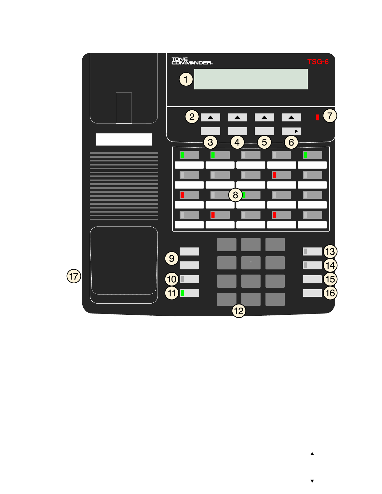
1) Display – shows the call state, caller ID, dialed digits, network call control messages, and elapsed time
during calls. When not on a call, the date, time of day, and softkey options are displayed.
The viewing angle can be adjusted by tilting the display, then changing the display contrast.
2) Softkeys – select the function displayed above the key on the second line of the display.
3) Call Key – selects the Call Directory, Call Log, and Call Identification Display modes.
4) Setup Key – enters Setup Mode.
5) Done Key – exits the current menu, saves any changes made, and returns to the previous menu
options.
6) MoreKey – cycles through the menu option groups in Setup Mode.
7) Message Waiting Indicator – a bright red indicator is lit when messages are waiting, controlled by the
network.

Tone Commander 6220-TSG-DD Installation Instructions
Page 8 13-280121 Rev. C
8) Multifunction Keys – select call appearances, activate network features, or dial personal speed dial
numbers. Red and green indicators on the keys show call appearance and feature status. The optional
6030X Button Expansion Module provides 30 additional multifunction keys.
Call Appearance State Indication
Idle OFF
Call Ringing Green – flashing
In Use by You Green – on steady
On Hold by You Green – winking
In Use at Another Terminal
or an Activated Feature Red – on steady
On Hold at Another Terminal Red – winking
9) Vol (Volume) Keys – adjust the receiver volume when on a call; adjust the ringer volume when on-
hook.
10) Mute Key – mutes the handset microphone. A red indicator on the key is lit when mute is active.
11) Spkr (Speaker) Key – disabled.
12) Dial Pad – dials telephone numbers, and sends DTMF tones to external equipment such as voice mail
systems. The dial pad is also used for number entry during setup.
13) Tran (Transfer) Key – places the current call on hold, and selects an idle call appearance for
transferring the call. A second press completes a transfer.
14) Conf (Conference) Key – adds other parties to a conference call.
15) Drop Key – removes the last party added to a conference call, or disconnects you from a call and
returns new dial tone when not in conference mode.
16) Hold Key – places a call on hold.
17) Handset Jack – a jack on the side of the telephone connects to the handset.

13-280121 Rev. C Page 9
Installation
Ordering ISDN Service ________________________________________
ISDN ordering forms may be supplied by your service provider. You can also print forms using the PC-
based Configuration Wizard. Please refer to Appendix A in this manual.
Consult your service provider to plan your service installation. Allow adequate time after cutover for testing
of all call appearances and programmed features. Ask your service provider for your SPID numbers, and
confirm the installation date.
S/T Version (6220T-TSG-DD) Installation _________________________
S/T models require an external NT1, such as the Tone Commander NT1U-223TC or NT1B-300TC.
Note: The NT1B-300TC-TSG model must be used if the NT1 is located inside the SCIF area.
Set the Termination Switches on the Telephone and NT1
Set the termination switches on the bottom of the telephone and on the NT1 to match the termination
impedance to your premises wiring configuration. Several typical wiring configurations are shown below,
with the appropriate switch setting.
We recommend the use of Category 3 or better unshielded twisted pair cable with T568A or T568B
connector wiring. Distances shown are the maximums for 24-gauge cable, and may vary for other cable
types.
Available switch settings are OFF and 100 ohms.

Tone Commander 6220-TSG-DD Installation Instructions
Page 10 13-280121 Rev. C
Basic Multipoint:
(recommended for most applications)
Short Multipoint:
Extended Point-to-Point:
Installation
13-280121 Rev. C Page 11
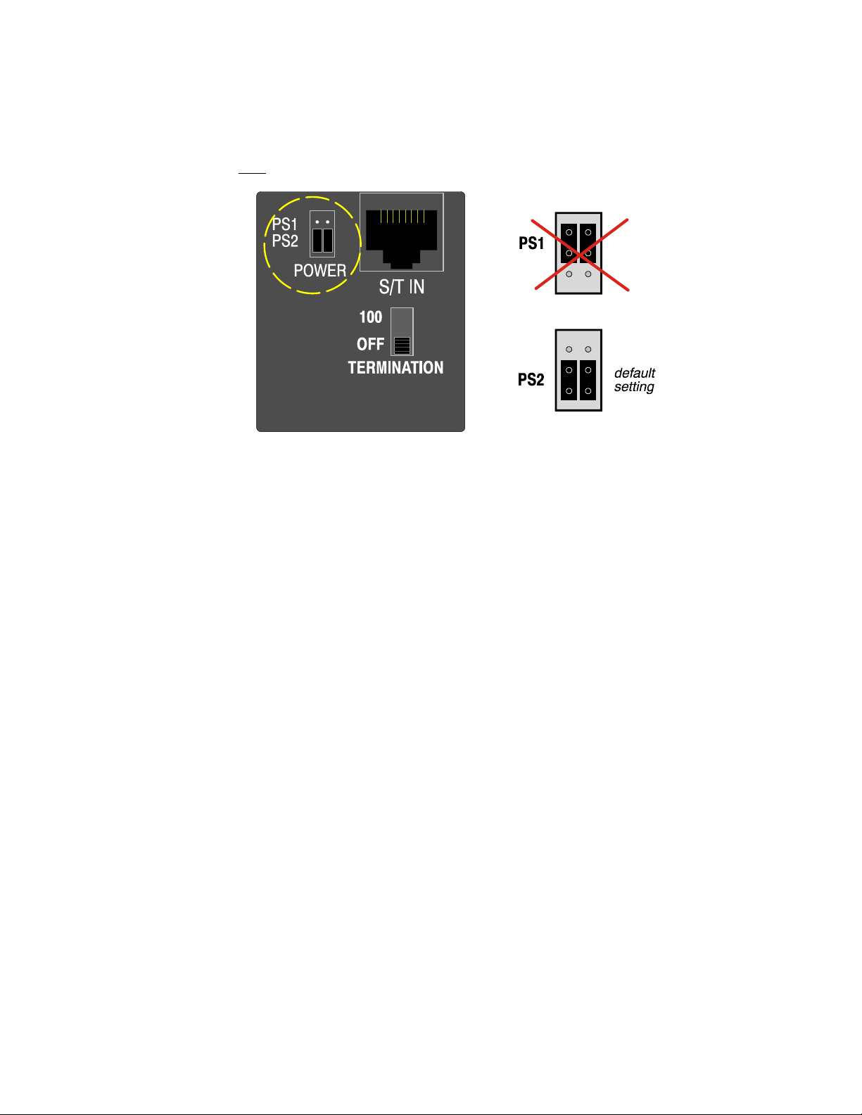
Set the Power Option Jumpers
Power for the telephone is provided by the included -PWR1 Desktop Power Supply using a PS2 power
arrangement (power on pins 7 and 8 from the TSG-DD1 Disconnect Device).
•Make sure that both power jumpers are set to PS2.
Connect the Handset
•Plug the supplied handset into the jack on the left side of the telephone. The jack location is shown on
page 7, item 17.
Tone Commander 6220-TSG-DD Installation Instructions
Page 12 13-280121 Rev. C
U Version (6220U-TSG-DD) Installation __________________________
This model includes a built-in NT1. Optional external ISDN S/T Terminal Equipment may share the
telephone's ISDN line by connecting to the S/T OUT jack on the telephone, which supplies PS1 and PS2
output power.
If you are not using external Terminal Equipment, no termination switch setting is required.
Connect the Handset
•Plug the supplied handset into the jack on the left side of the telephone. Refer to page 7, item 17.
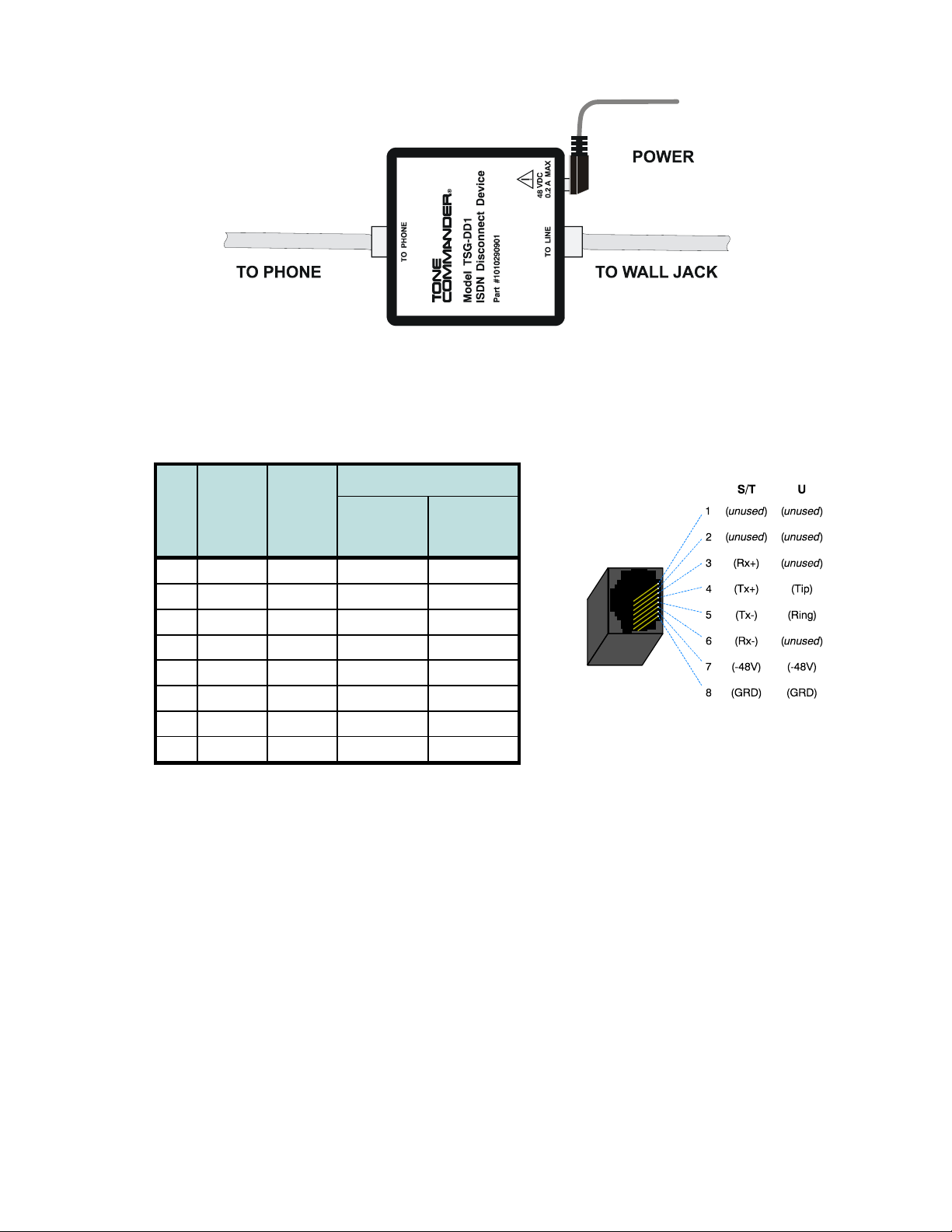
Line and Power Connections __________________________________
The TSG-DD1 disconnect device completely disconnects the ISDN line when power is not applied. It is
installed in series with the phone’s line cord.
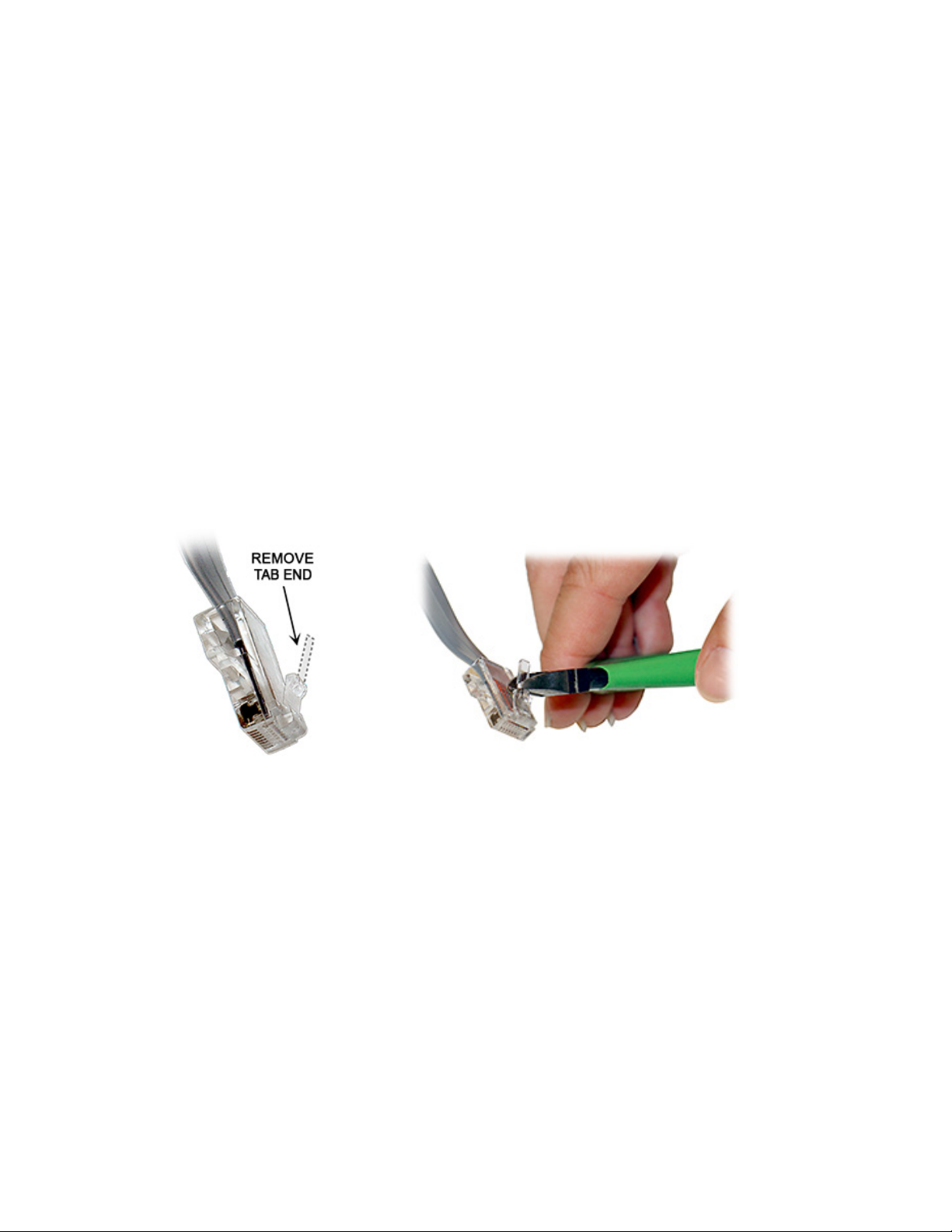
•Clip the ends off of the retainer tabs on the cord that connects the TSG-DD1 to the phone, to prevent
the TSG-DD1 from being disconnected from the phone. Clip the tabs as shown; do not completely
remove the tabs!
•Install the TSG-DD1 in series with the phone’s line cord as shown on the following page.
For the S/T version (6220T-TSG-DD), connect the S/T IN jack on the telephone to the TO PHONE jack
on the TSG-DD1, using an 8-conductor line cord.
For the U version (6220U-TSG-DD), connect the U IN jack on the telephone to the TO PHONE jack on
the TSG-DD1, using an 8-conductor line cord.
•Plug the supplied Tone Commander -PWR1 Desktop Power Supply into the 48 VDC jack on the TSG-
DD1.
Do not connect the power supply directly to the phone.
Installation
13-280121 Rev. C Page 13
Wall Jack Wiring
Pin
#
S/T
Signal
U
Signal
Wire Color
T568 A T568 B
*
(AT&T
258A)
5 Tx- Ring WHT-BLU WHT-BLU
4 Tx+ Tip BLU BLU
1 unused unused WHT-GRN WHT-ORN
2 unused unused GRN ORN
3 Rx+ unused WHT-ORN WHT-GRN
6 Rx- unused ORN GRN
7 -48V -48V WHT-BRN WHT-BRN
8 GRD GRD BRN BRN
•T568 B jacks are recommended; they allow conventional station pair ordering when connecting to
S/T punchdown blocks on NT1 racks.
Use Category 3 or better unshielded twisted pair cable for all premises wiring.
Modular Jack Pinout

Tone Commander 6220-TSG-DD Installation Instructions
Page 14 13-280121 Rev. C
Wall Mounting _______________________________________________
Robust handset retainer clips for wall mount use are available on request from Tone Commander.
Rotating the Base
The phone base must be rotated for wall mounting.
•Disconnect the line cord.
•Remove the retaining screw in the center of the base.
•Press the top of the tall edge of the base to disengage the snap tabs, and then lift the base from the
telephone body.
Do not touch the expansion connector. If using the 6030X or 6002TA, leave the expansion cable
plugged into the phone.
•Turn the base 180°, insert the tabs on the short edge of the base into the holes near the display end of
the telephone, and then snap the tall side of the base onto the telephone.
•Replace the retaining screw (required for UL compliance).
Attaching to a wall mount jack
Note: The TSG-DD1 Disconnect Device must be connected in series with the ISDN line (page 12).
•6220T-TSG-DD: Plug the line cord from the TO PHONE jack on the TSG-DD1 into the S/T IN jack on
the telephone. Route the cord under the guide tabs on the base. Connect an 8-conductor line cord
between the TO LINE jack on the TSG-DD1 and the wall jack.
Plug the supplied Tone Commander -PWR1 Desktop Power Supply into the 48 VDC jack on the TSG-
DD1.
6220U-TSG-DD: Plug the line cord from the TO PHONE jack on the TSG-DD1 into the U IN jack on the
telephone. Route the cord under the guide tabs on the base. Connect an 8-conductor line cord between
the TO LINE jack on the TSG-DD1 and the wall jack.
Plug the supplied Tone Commander -PWR1 Desktop Power Supply into the 48 VDC jack on the TSG-
DD1.
Do not connect the power supply directly to the phone.
•Hang the telephone on the wall plate mounting studs. Press down firmly to lock in place.
The phone can also be mounted directly to the wall with screws, and connected to a line jack or to the
TSG-DD1 with the supplied line co

Installation
13-280121 Rev. C Page 15
Configure the Set ____________________________________________
ISDN configuration is performed automatically in many cases. The telephone set will detect the switch type,
set the SPID number, and download other setup parameters when these features are available from the
Telco central office.
You will be prompted for any required setup information that cannot be set automatically.
Initialization
A self-test is performed upon power up. Press any key to begin initialization with the network. Unattended
initialization begins automatically after a short random time interval. This delay prevents multiple terminals
at a site from initializing simultaneously after a power outage.
The display will show progress while establishing the communication layers. When all three communication
layers are established, the TEI (Terminal Endpoint Identifier) and switch type will be shown for two
seconds.
SPID Entry
The SPID number will be assigned automatically if the network supports AutoSPID. If there is more than
one SPID available for your terminal, you will be prompted to select your primary telephone number.
If AutoSPID is not supported, you will be prompted to enter the phone’s primary telephone number, which
is used by the phone to generate a SPID number. Enter the number with the dial pad, and then press the
Done key.
BKSP (backspace) deletes the previous digit.
National ISDN – enter your full 10-digit telephone number
(including area code)
5ESS Custom ISDN – enter your 7-digit telephone number
Parameter Download (National ISDN only)
Parameter Download is a network feature that Identifies Call Appearance and Feature Activator keys that
are assigned to your line so that your phone may be configured automatically.
Note: Speed Dial, DSS keys, and other user preference settings are not configured by Parameter
Download.
If Parameter Download is not supported, the following screen may appear momentarily, prompting you to
manually configure the telephone at a later time (see page 18).
Automatic Button Detection (5ESS Custom ISDN only)
Press each multifunction key. The phone will discover the key's network assignment. Keys that have no
network assignment may be used for speed dialing – please refer to page 22.
L1:OK L2:OK TEI:123
L3:OK SWITCH=5ESS NI-X
ENTER PRIMARY PHONE #
999-555-1243 |BKSP
NO PARAMETER DOWNLOAD
PRESS SETUP TO CONFIGURE

Tone Commander 6220-TSG-DD Installation Instructions
Page 16 13-280121 Rev. C
Using Local Inspect to Verify Keys
Local Inspect allows you to identify the call appearance or feature assignment of each configured key,
directory number bearer capabilities, and the feature indicator assignment for the Message Waiting
Indicator. Please refer to page 27.
Label the Set ________________________________________________
Label the multifunction keys with the telephone number, feature name, speed dial party name, or other
appropriate designation. A perforated label sheet is provided with the telephone.
An ISDN Telephone Setup Wizard for Windows can be downloaded from www.teotech.com. This program
prints key labels and service ordering forms. A Microsoft Word template for key labels only is also
available. Please refer to Appendix A on page 37. Label text is on 1” centers, with 0.9” text space for each
key.
To install the labels, remove the plastic overlay surrounding the multifunction keys. Peel off the protective
strips from the adhesive in the grooves beneath the keys. Insert the label strips in the grooves, and then
replace the overlay.

13-280121 Rev. C Page 17
Installation Options
Options in this section are typically set at the time of installation. Many options can be set automatically by
the AutoSPID, Automatic Switch Detect, and Parameter Download features, if supported on the network.
The following options can be changed from the Installation Options menu:
•SPID •Keys and Indicators
•Parameter Download •Installation Password
•Terminal Mode •Reset to Default Settings
Installation Options Menu _____________________________________
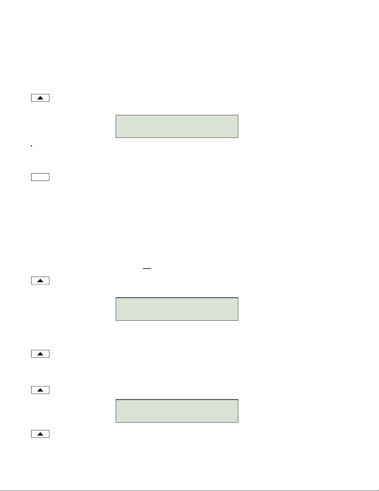
You can enter the Installation Options menu when the phone is idle.
Press the Setup key.
Select INSTL.
When appears in the top line of the display, you can press the Morekey to see additional
menu selections.
Notes: The PARAM and MODE options are only available with National ISDN.
The POTS option is only available when the Model 6002TA Analog Port Terminal Adapter is
installed.
A password may be set to prevent unauthorized entry into the Installation Options menu.
When prompted for a password, enter your password with the dial pad. Press the Done
key after entering the password.
To change or remove the password, please refer to page 25.
Setup
More
SETUP MENU
INSTL ADMIN USER POTS
INSTALLATION OPTIONS \
SPID PARAM KEYS MSG
INSTALLATION OPTIONS \
MODE PASSWD RESET
Tone Commander 6220-TSG-DD Installation Instructions
Page 18 13-280121 Rev. C
SPID Entry __________________________________________________
A unique SPID (Service Profile IDentifier) is required for operation of the 6220-TSG-DD. If the network
supports AutoSPID, a SPID that is assigned to your ISDN line can be automatically selected. If National
ISDN generic SPID assignments are used by your service provider, your SPID will consist of your primary
telephone number followed by “0101” (e.g., 42534910000101). Contact your network service provider for
your telephone’s SPID.
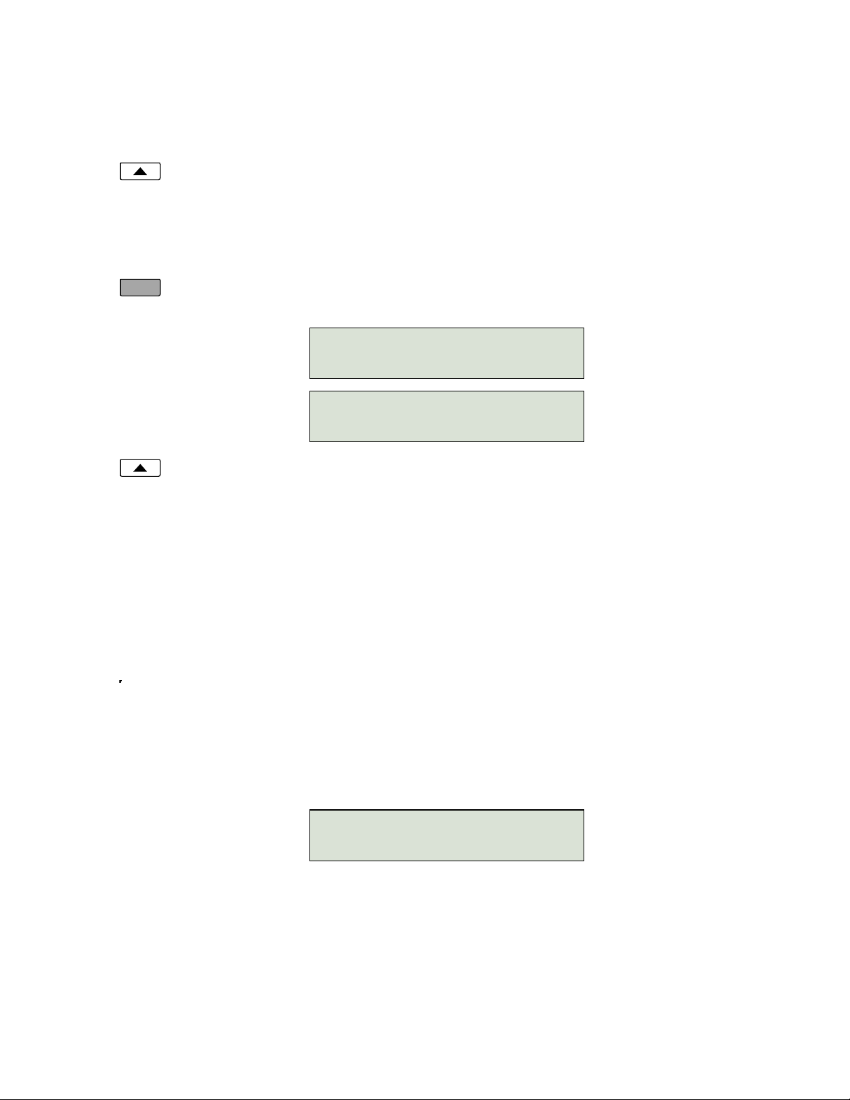
From the Installation Options menu, select SPID.
(Setup →INSTL →SPID)
Using the dial pad, enter the SPID number supplied by your network service provider.
If you need to make corrections, select
BKSP (backspace) to delete the previous digit.
CLEARremoves all digits, allowing you to start over.
When digits have been entered, press the Done key to return to the Installation Options menu or
press the Setup key to exit Setup Mode.
Parameter Download _________________________________________
(National ISDN only)
ISDN Parameter Download is an automated feature for configuring Call Appearance and Feature Activator
keys. If configured for auto download, a Parameter Download is executed when the phone initializes with a
new SPID, or when requested by the network, due to a line configuration change.
Note: Speed Dial and DSS keys are not configured by Parameter Download.
From the Installation Options menu, select PARAM.
(Setup →INSTL →PARAM)
Starting a Download
Select START to manually initiate a Parameter Download.
Enabling/Disabling Automatic Download
Select AUTO.
Select ENABLE or DISABLE.
Done
ID=42534910000101
|BKSP CLEAR
PARAMETER DOWNLOAD
START AUTO
AUTO DOWNLOAD=ENABLED
ENABLE DISABLE
Installation Options
13-280121 Rev. C Page 19
Configuring Keys and Indicators ________________________________
If the network does not support Parameter Download, you can assign call appearances, directory numbers
and feature activators using this option.
From the Installation Options menu, select KEYS.
(Setup →INSTL →KEYS)
The status indicator for each key will indicate the current setting:
Green – Call Appearance or DSS
Red – Feature Activator
Off – Unused or Speed Dial
On the phone or Button Expansion Module, press the multifunction key to be programmed.
The selected key’s indicator will alternately flash red and green.
Select CA/DN (Call Appearance /Directory Number), FA (Feature Activator), DSS (Direct Station
Select), SPDIAL (Speed Dial), or UNUSED from the menu.
Programming procedures for each key type are described below.
Call Appearance / Directory Number Keys
These “line” keys are used to place and answer calls. If you have BASIC service or are connected to a
Nortel Meridian 1 Option Series PBX, each directory number key is assigned a unique directory number.
If you have CACH EKTS service, one directory number may be assigned to multiple Call Appearance
keys; multiple calls can be handled on one directory number.
Enter the assigned directory number with the dial pad.
For the Nortel Meridian 1 Option Series PBX, enter the same number of digits used in the PBX
dialing plan (2 to 7 digits).
If you need to make corrections while entering numbers, select
BKSP (backspace) to delete the
previous digit.
You can press the Done key to return to key selection.
12=CA/DN \
CA/DN FA DSS SPDIAL
12=CA/DN \
UNUSED
12=CA/DN# 5559876
|BKSP ORIG RESERV

Tone Commander 6220-TSG-DD Installation Instructions
Page 20 13-280121 Rev. C
Automatic Call Appearance Selection
A call appearance is automatically selected when originating a new call, answering an incoming call, or
conferencing or transferring a call. Three configuration options determine how call appearances are
selected:
Call Preference (User option) – determines whether a new call is originated when you lift the handset.
If set to NONE, you must manually press a Call Appearance key to originate a call.
Originating DN – only call appearances with this option set to YES will be automatically selected for call
origination.
CA Reservation – within the group of originating DNs, call appearances set for NOT RESERVED are
selected first, followed by OUTGOING ONLY, followed by OUT/PRIORITY call appearances
(OUTGOING ONLY call appearances are selected first for conferencing and transferring). Within each
subgroup, call appearances are selected in ascending order. INCOMING ONLY call appearances are
never selected for an outgoing call. If an idle CA is not found, “SELECT AN IDLE LINE” is displayed.
To change the Originating DN assignment:
Select ORIG.
Select YES or NO from the Originating DN menu.
Press the Done key to return to the CA/DN menu.
To change call appearance reservation:
Select RESERV.
Select the call appearance reservation for this CA/DN.
OUT – Originate (outgoing calls) only.
IN – Terminate (incoming calls) only.
PRI – Outgoing or priority incoming calls only.
NOT – Not Reserved - default value for all keys.
Press the Done key to return to the CA/DN menu.
Done
Done
Table of contents
Popular Telephone manuals by other brands

Axess Telecom
Axess Telecom ACW-1xP800 user manual

Panasonic
Panasonic EASA-PHONE KX-T3280 operating instructions

Auer Signal
Auer Signal wFT3 operating manual

Cooper safety
Cooper safety VoCALL CFVCM User manual & log book

Panasonic
Panasonic KX-FPC91 operating instructions

Connection Electronics
Connection Electronics MFC98 manual


