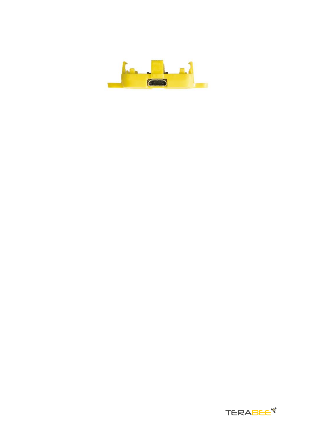
3. USB backboard use
The USB backboard comes with a standard Micro-USB connector.
3.1. Graphical User Interface
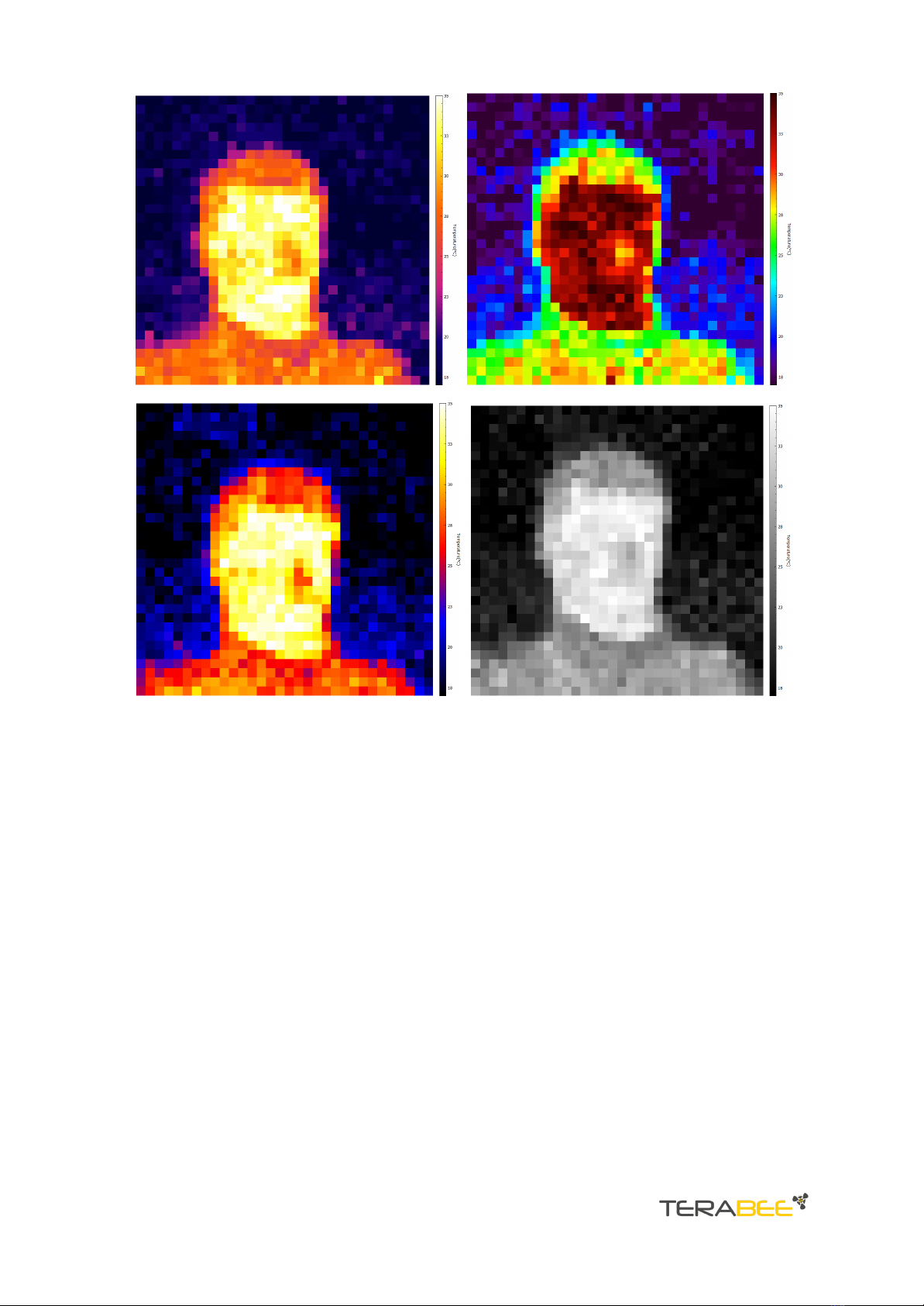
A free Graphical User Interface (GUI) is available, providing an easy way to visualize the
data from your TeraRanger Evo Thermal sensor. This is useful for demonstration,
testing purposes and checking some of the basic parameters of the sensor. It also
provides an option to easily record thermal images, export raw data and upgrade the
firmware running on the device.
The GUI is available for download here: GUI Download. (See “Downloads” section of the
TeraRanger Evo Thermal product page).
3.1.1. Prerequisites
For usage on Windows 7 and Windows 8, please download the Virtual COM Port driver
from http://www.st.com/en/development-tools/stsw-stm32102.html and follow the
”ReadMe file” instructions given by the installer . After successful installation, unplug
the interface for a few seconds, and plug it back in. The virtual COM port should now be
available on your PC.
Users of Windows 10 do not need to download this driver as the built in Windows driver
is recommended.
3.1.2. Basic operation
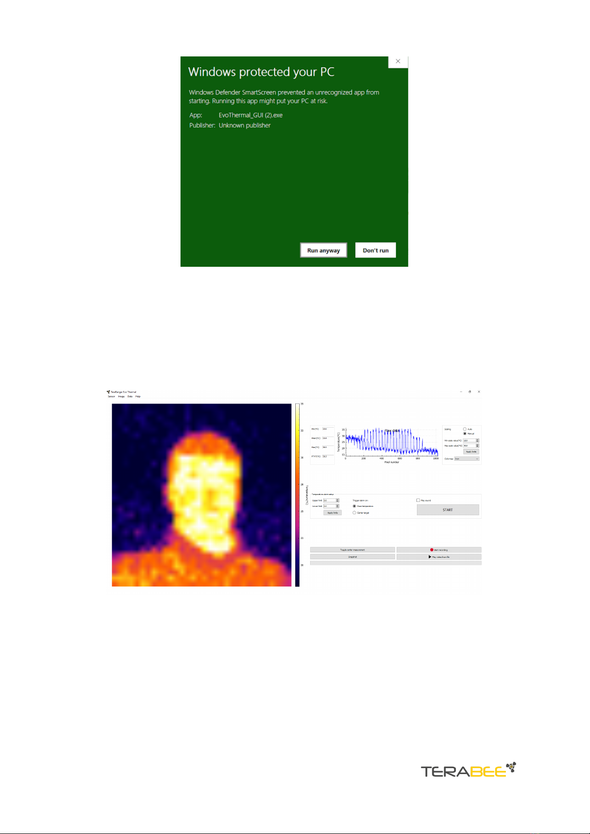
During installation of the GUI, you might receive a notification from Windows about an
unknown application trying to start (Figure 6). In the “Windows protected your PC”
screen select More info > Run anyway to proceed with Evo Thermal GUI installation
and please be advised that running this application will not put your PC at risk.
Copyright © Terabee 2023
Terabee, 90 rue Henri Fabre
01630 Saint-Genis-Pouilly, France (next to CERN)
TeraRanger Evo Thermal - User manual
Version 1.0