Teracom TCW122B-RR User manual


TCW122B-RR_R2.4 -March 2019 Page 1
1. Short description
TCW122B-RR is a remote relay control module with an embedded WEB server for setup. The device
has two digital inputs and two relays, with normally open and normally closed contacts.
TCW122B-RR can works in two modes – “Client” or “Server”. The “Client” sends periodically the
status of its digital inputs to the “Server”. As an answer, the “Server” returns its digital inputs
status. Activating the input of “Client” switches on the relay of “Server” and vice versa. This
configuration is used to control remote devices without a browser or to extend a digital signal to
a remote location on the network.
2. Features
•Password protected web-based configuration;
•2 digital input with "logic level" and "dry contact" modes;
•2 relays with NO and NC contacts;
•Encrypted communication protocol;
•Device ID filtering;
•Manual or DHCP network configuration;
•Removable terminal connectors - separated for inputs and outputs;
•Autonomous operation;
•Remote firmware update.
3. Specifications
•Physical characteristics
Dimensions: 107 x 72 x 32 mm
Weight: 110 g
•Environmental limits
Operating тemperature range: -20 to 55°C
Storage temperature range: -25 to 60°C
Operating relative humidity range: 5 to 85% (non-condensing)
•Warranty
Warranty period: 3 years
•Power requirements
Input Voltage: 10 to 14 VDC
Input Current: 200 mA @ 12 VDC (with both relays ON)
•Ethernet connectivity
10 Mbit/s transfer rate
Half-duplex mode only
Auto-negotiation not supported
•Digital inputs
Isolation: Non isolated
Mode: Dry contact or Logic level
Maximum input voltage: +5.5VDC
Minimum input voltage for high logic level: +2.5VDC
Maximum input voltage for low logic level: +0.8VDC
Sampling rate: 10mS
Digital filtering time interval: 30mS

TCW122B-RR_R2.4 -March 2019 Page 2
•Relay outputs
Type: Form C (N.O. and N.C. contacts)
Contact current rating: 3 A @ 24 VDC/30 VAC (resistive load)
Initial insulation resistance: 100 mega-ohms (min.) @ 500 VDC
Mechanical endurance: 10 000 000 operations
Electrical endurance: 100 000 operations @ 3 A resistive load
Contact resistance: 50 milli-ohms max. (initial value)
Minimum pulse output: 1 Hz at rated load
•Internal FLASH memory
Endurance: 100 000 cycles (Every relay status and settings change is a memory cycle.)
4. Connectors
Inputs and outputs locations are shown below:
Connector 1– Power - 2.1x5.5mm connector,
central positive
Connector 2, Pin1 – Digital input 1 (Din1)*
Connector 2, Pin2 – Digital input 2 (Din2)*
Connector 2, Pin3 – Ground
Connector 2, Pin4 – Not used
Connector 2, Pin5 – Not used
Connector 2, Pin6 – Ground
Connector 2, Pin7 – Not used
Connector 2, Pin8 – Not used
Connector 3 –Ethernet - RJ45
Connector 4, Pin1 –NC Relay1
Connector 4, Pin2 –COM Relay1
Connector 4, Pin3 –NO Relay1
Connector 5, Pin1 – NC Relay2
Connector 5, Pin1 –COM Relay2
Connector 5, Pin1 –NO Relay2
* Operating mode is selected by jumper DI1/DI2 -closed for “dry contact” and open for “logic
level”. By default, jumpers are closed.
5. LED indicators
The following indicators show the status of the controller:
•Relay1/Relay2 (green) – these LEDs are illuminated whenever the corresponding relay
is activated (the NO contact is closed and the NC contact is open);
•Sts (red) – flashes when the main program of the controller is executed;
•Log (yellow) – ON when somebody is logged via the WEB interface, flashes on 2
seconds when the client and server are connected;
•Net (green/red) – red when the device is linked, yellow when there is an activity.
6. Powering
TCW122B-RR is designed to be supplied by adapter SYS1421-0612-W2E or similar, intended for use
in the conditions of overvoltage category II, and priorly assessed for compliance with safety
requirements. The power supply equipment shall be resistant to short circuit and overload in the
secondary circuit.
TCW122B-RR_R2.4 -March 2019 Page 3
When in use do not position the equipment so that it is difficult to disconnect the device from the
power supply.
7. Installation
This device must be installed by qualified personnel.
This device must not be installed directly outdoors.
The installation consists of mounting the device, connecting to an IP network, connecting inputs
and outputs, providing power and configuring via a web browser.
TCW122B-RR can be wall or flat, not flammable surface mounted, in a clean and dry location room.
Ventilation is recommended for installations where the ambient air temperature is expected to be
high.
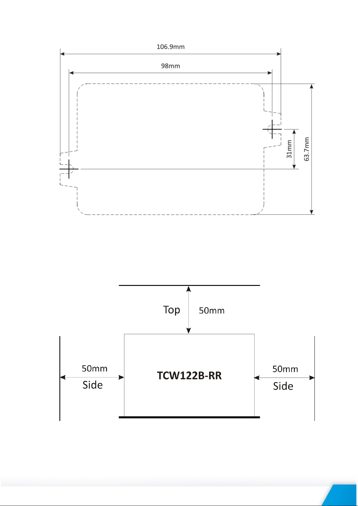
Mount the device to a wall by using two plastic dowels 8x60mm (example Würth GmbH 0912
802 002) and two dowel screws 6x70mm (example Würth GmbH 0157 06 70). Attach the screws
to the surface vertically. See Appendix-A, fig. 1 for mechanical details.
Maintain spacing from adjacent equipment. Allow 50 mm of space on all sides, as shown in fig.2 in
Appendix A, this provides ventilation and electrical isolation.
8. Configuration
Please follow the steps below for proper installation :
1. Mount the controller in a dry and ventilated place.
2. Connect the Ethernet port to a 10/100MB Ethernet network. For direct connection to
a PC using a “crossover” cable.
3. Connect the I/O pins of the controller according to the required application.
4. Connect the power supply.
If the red LED (STS) blinks, the main program of the controller is executed. By default TCW122B-RR comes
with the following network settings:
IP address: 192.168.1.2, Subnet Mask: 255.255.255.0, Default Gateway: 192.168.1.1
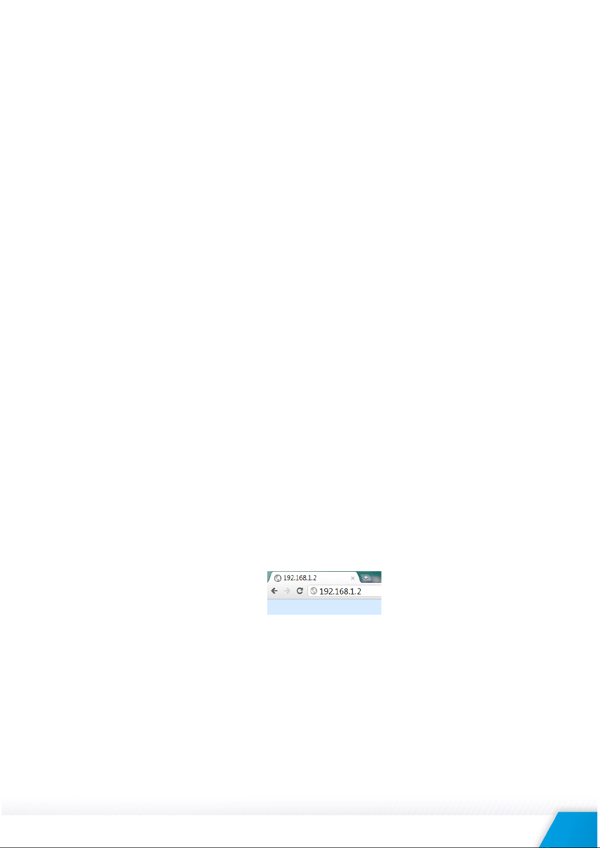
Communication with TCW122B-RR can be established by assigning a temporary IP address to the
computer. This address should be on the same network (for example 192.168.1.3). To get access
to the web interface, you should type http://192.168.1.2 into the browser.
If the network settings are correct, the “Login” page will appear.
The web-based interface allows configuration, monitoring, and control.
8.1. Login page
After opening the Login page, authorization data must be entered (by default username=admin,
password=admin). It is recommended to change the username and password to prevent
unauthorized access to the controller.

TCW122B-RR_R2.4 -March 2019 Page 4
The controller supports one active session – only one user can operate the device over the WEB
interface. If another user tries to login, the message “Someone is logged in” appears:
The active session will stay open until the "Monitoring" page is open. Inactivity on other pages
or closing the browser without logoff will terminate the session automatically in 4 minutes.
8.2. Monitoring page
The “Monitoring” page provides information about the state of the relays, digital inputs and
the status of connection:
8.3. General setup page
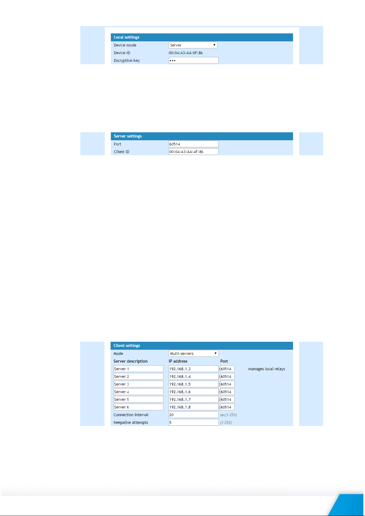
8.3.1. “Local setting”
•Device mode – “Client” or “Server”. The “Client” initiates communication, “Server” just
responds to the “Client” messages.
•Device ID – this is information field. The value can be used for extra communication
filtering – see “Client settings”;
•Encryption key -the communication between devices is always encrypted. When the
field is empty - default key, stored in the ROM of the device, is used. All devices have
the same default key.
TCW122B-RR_R2.4 -March 2019 Page 5
8.3.2. Server settings
This part can be set up if the Server mode is chosen.
•Port – Port on which the “Server” listens for requests from the “Client”;
•Client ID – by default is “00-00-00-00-00-00”. In this case, there is no device ID filtering.
If extra filtering is needed the value of “Device ID” field of “Client” should be filled in
here.
8.3.3. Client settings
This part can be set up if the Client mode is chosen.
•Mode – “Single-server” or “Multi-servers”.
In Single-server mode one “Client” communicates with one “Server”. The status of
Client’s digital inputs manages corresponding relays of the “Server”.
In Multi-servers mode one “Client” communicates with up to 6 “Servers”. The status
of Client’s digital inputs manages corresponding relays of the all “Servers”. Only the
status of digital inputs of “Server1” manages corresponding relays of the “Client”.
•Server IP : Port – network settings of Server. It is mandatory that port here should be
the same like in field “Port” on “Server” device;
•Connection interval – time in seconds in which the “Client” sends a request to Server.
In case of input activation, the “Client” sends the request immediately, doesn’t matter
how many seconds are passed from the previous regular request. This guarantee
immediate response of the system. In the example the “Client” sends requests on
every 20 seconds;
•Keep alive attempt – a number of sequential request (on connection interval) after
which the connection is considered not alive. In the example, if no answer from server
in 100 seconds (5 attempts x 20 seconds) connection will consider broken.
8.3.4. General settings
Descriptions and refresh interval for monitoring page can be set here.
Automatic monitoring page refresh interval can be set from 1 to 253 second. If 0 is chosen -
no automatic refresh. In the example, the monitoring page will be refreshed every second.

TCW122B-RR_R2.4 -March 2019 Page 6
In case of losing the communication, relays can go in permanent ON or permanent OFF
state.
Automatic monitoring page refresh interval can be set from 1 to 253 second.
9. Typical connections
The Client-server model allows connecting the devices in different networks.
9.1. Both devices are connected to the Internet
Both devices have with public IP addresses. For “Server” device the IP address should be static.
9.2. Both devices are connected to one LAN
Both devices have private addresses. For “Server” device the IP address should be static.
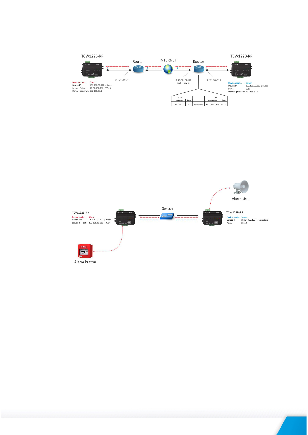
9.3. “Client” is connected to LAN and “Server” is connected to the Internet
“Client” device has a private IP address; valid default gateway should be set up.
“Server” device has a public static IP address.
9.4. “Client” and “Server” are connected to different LAN’s
TCW122B-RR_R2.4 -March 2019 Page 7
“Client” device has private IP address; valid default gateway should be set up.
“Server” device is behind the router with public static IP address. Valid port forwarding
settings should be set up in the router.
10. Typical application
The examples and diagrams in this manual are included solely for illustrative purposes. Because of
the many variables and requirements associated with any particular installation, Teracom Ltd.
cannot assume responsibility or liability for actual use based on the examples and diagrams.
10.1. Single direction remote control
TCW122B-RR allows device control at a remote location. In the example, alarm button
connected to the “Client” device activates the siren, connected to the “Server” device.
TCW122B-RR_R2.4 -March 2019 Page 8
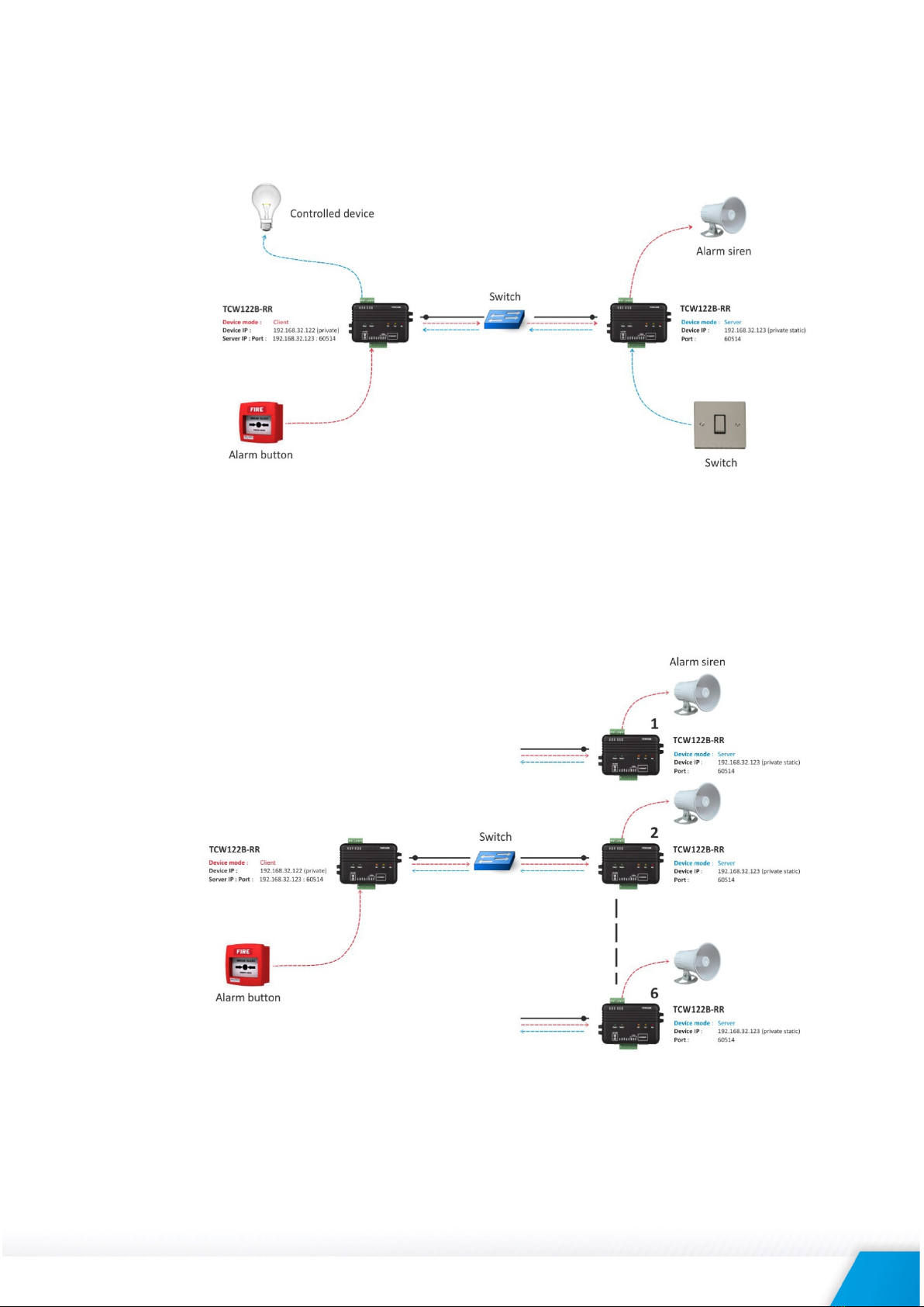
10.2. Bi-directional remote control
TCW122B-RR allows bidirectional remote control. Activating the input of one device switches
on the relay in the opposite device and vice versa.
10.3. One “Client” to many “Servers”
In Multi-servers mode one “Client” communicates with up to 6 “Servers”. Activating the input
of “Client” switches on the corresponding relay of all “Servers”. Only the digital inputs of
“Server1” switch on the relays of “Client”.
TCW122B-RR_R2.4 -March 2019 Page 9
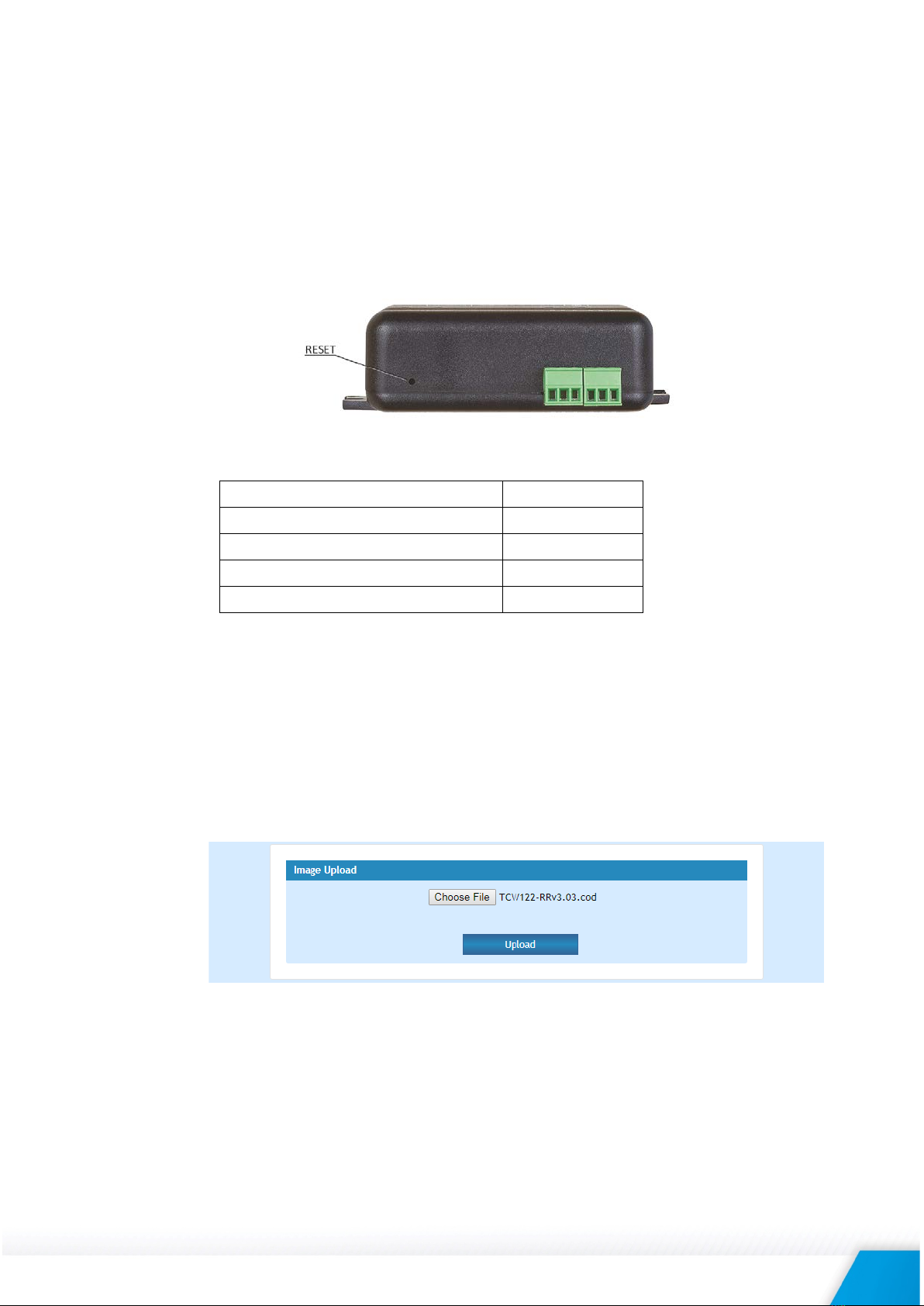
11. Factory default settings
TCW122B-RR can be restored to its original factory default settings, following the steps below:
•Turn off the power supply;
•Press and hold the RESET button then turn on the power supply;
•After turning the power supply release the RESET button. The LED’s STS and LOG will
flash 14 times after that only the STS LED will continue to blink. The controller is
restored to its default settings.
The factory default settings are:
User Name (Admin)
admin
Password (Admin)
admin
IP Address
192.168.1.2
Subnet Mask
255.255.255.0
Default Gateway
192.168.1.1
12. Firmware update
TCW122B-RR supports remote firmware update. To update the device follow the steps below:
•Go to www.teracomsystems.com and download the latest firmware version file from
TCW122B-RR product page;
•Go to the device login page, enter a username, and password and press the “Login”
button;
•Go to “Update” menu, select the update .cod file and press “upload” button;
•After the firmware update is completed, you will be forwarded to the device Login
page.
Attention! Don’t turn off the power supply during the update. Turning off the power supply will
damage the device.
For some updates factory default settings procedure is mandatory.

TCW122B-RR_R2.4 -March 2019 Page 10
13. Environment information
This equipment is intended for use in a Pollution Degree 2 environment, at altitudes up to 2000
meters.
When the controller is a part of a system, the other elements of the system shall comply with the
EMC requirements and shall be intended for use in the same ambient conditions.
14. Safety
This device must not be used for medical, life-saving purposes or for any purpose where its failure
could cause serious injury or the loss of life.
To reduce the risk of fire, only flexible stranded wire, with cross section 0.5mm² or larger for wiring
of digital inputs and relay outputs of the device should be used.
To avoid electric shock and fire hazard, do not expose this product to liquids, rain, or moisture. Do
not expose this product to dripping or splashing liquids, rain, or moisture. Objects filled with
liquids, such as vases, should not be placed on this device.
There is a risk of overheating (damage) of the controller, if recommended free spaces to adjacent
devices are not ensured. The joint part with external component shall have space for
attachment/removal of the cable after installation.
Teracom does not guarantee successful operation of the product if the product was used under
conditions deviating from the product specifications.
To ensure that the system (two devices) works correctly follow the steps below:
•ensure that the devices are installed correctly, refer this user manual;
•log in to the devices via browser program;
•make proper set up for client and server devices;
•the yellow LED’s of both devices blink, if they are “in connection”;
•set up the digital inputs to work in “dry contact” mode;
•short the digital input of ”client” device – appropriate relay of “server” device should
be activated;
•short the digital input of ”server” device – appropriate relay of “client” device should
be activated.
If the equipment is used in a manner not specified by the manufacturer, the protection provided
by the equipment may be impaired.
In no event will Teracom Ltd. be responsible or liable for indirect or consequential damages
resulting from the use or application of this equipment.
15. Maintenance
Upon completion of any service or repairs to the device or once per year, safety check must be
performed to determine that this product is in proper operating condition.
Clean the device only with dry cloth. Do not use a liquid cleaner or an aerosol cleaner. Do not use
a magnetic/static cleaning device (dust remover) or any kind of abrasive materials to clean the
device.
TCW122B-RR_R2.4 -March 2019 Page 11
Appendix A
Fig.1
Fig.2
TCW122B-RR_R2.4 -March 2019 Page 12
Other manuals for TCW122B-RR
1
Table of contents
Other Teracom Control Unit manuals


Popular Control Unit manuals by other brands


Cinterion
Cinterion MC75i Hardware interface description

Gioteck
Gioteck IN2LINK G365F manual

Emerson
Emerson SEMPELL Installation and maintenance instructions

ARMATURA
ARMATURA AMT-FAPVS-21 user manual

Sun Microsystems
Sun Microsystems Sun Blade X6440 s installation guide

Emco
Emco A1100EVR GUARDIAN installation instructions


