4
5 COMMISSIONING
A. Connecting to electrical supply
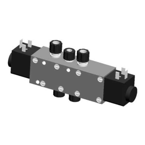
For single acting pneumatic actuator with
solenoid valve wired for normally closed
positions.
1. Ensure that the adjusting nut on the filter
regulator is fully out (anti-clockwise) then
turn on the air supply to the inlet supply of
the filter regulator.
2. Connect the electrical supply to the
solenoidvalve.
3. Energize the solenoid valve.
4. Screw in the adjusting nut on the filter
regulator (clockwise) until the working
pressure is obtained (Refer to certified
General Arrangement drawing for details of
air pressure requirements). The valve stem
(4) will go to the fully instroked position.
5. To ensure correct and safe operation, check
the outstroke by de-energizing the solenoid
valve. As the air pressure is relieved, the
stem (4) will move to the fully outstroked
position.
WARNING!
Care must be taken when exhausting the solenoid
valve that the area close to the valve is kept clear.
Do not attempt to obstruct exhausting orifices
byhand.
6 STORAGE
Indoor storage of valves is recommended.
Ifprolonged storage is anticipated, the valves
should be stored in humidity controlled
storageareas.
If valves are ordered to a more stringent
cleaning and storage procedure, the
recommendations in that procedure should
befollowed.
7 INSTALLATION AND WELDING
When valves are received, an enclosed ‘Packing
Note’ will provide an itemised statement of all
valves and parts included in the shipment. The
recipient should check and account for each
item on the list, and then keep this packing note
as a permanent record for these valves/parts.
Unloading the valves should be done with care.
Remember that, although the valve is a rugged
piece of equipment, it may still be damaged by
abusive handling. Skidded or chocked valves
should not be unskidded until immediately
before installation.
Improper installation of a valve can have very
serious consequences, resulting in a possible
malfunction, which may result in extensive
and costly repairs. Compliance with the
following recommendations will do much to
assure optimum performance of the valve
afterinstallation.
It is essential that precautions be taken to
prohibit the entry of foreign debris inside
the valve, which could damage the seating
surfacesbefore and/or after installation.
B. Solenoid valve check
Next, it is necessary to check the functional
operation of the solenoid to ensure that it
responds correctly via the control system.
1. With solenoid valve energized, the stem (4)
and the indicator plate (39) will move to a
fully instroked position. This will indicate the
correct operation of the solenoid. Open limit
switch operation can also be checked at this
stage.
2. Select the ‘close valve’ position via the
control system (for on-load testing) i.e.
solenoid de-energized and check the
actuator has moved to the fully outstroked
position. Closed limit switch operation can
also be checked at this stage.
3. Select the ‘open valve’ position via the
control system (for on-load testing) and
check that the actuator has moved to the
fully instroked position.
4. With the working air pressure still set, a
simulated turbine trip should now be carried
out via the control system to ensure the
correct solenoid response.
5. Local on-load testing can be achieved by
operating the push button on the solenoid
valve. When the actuator is fully outstroked,
release the push button and the pneumatic
actuator will return to the fully instroked
position.
6. After satisfactory completion of the above
steps, fully screw out (anti-clockwise) the
adjusting nut on the filter regulator and de-
energize the solenoid valve. The stem (4) will
move to the fully outstroked position.
When the valve is required to be put into
service, screw in (clockwise) the adjusting
nut on the filter regulator until the working
air pressure is obtained. The stem (4) will
move to the fully instroked position when
the valve is ready for service.
SEMPELL DEWRANCE BLEED STEAM CHECK VALVES
InstallatIon and maIntenance InstructIons
