Teral CTF3-HOH User manual

Create future with water and air
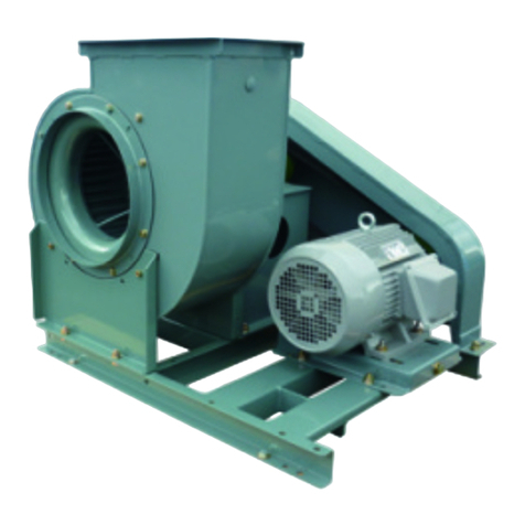
Centrifugal Fan
Turbo Fan
Model CTF3-HOH
Instruction Manual
Do not operate, maintain or inspect this device until you have read and
understood this manual.
Keep this manual in a safe place where it can be referred to at any time.
Ensure that copies of this manual are supplied to the all those who
operate, maintain or inspect this device.
TERAL INC.

Limit of Liability
1. Warranty period is for period of 18 months after date of the bill of lading or 12 months after
installation whichever earlier.
2. During warranty period, equipment sold is warranted to the Buyer to be free from defective
material and workmanship. If Buyer notifies Seller in writing of any claimed defect in the
equipment and if, after appropriate reasonable opportunity to inspect and remedy any
defect by Seller, the equipment is found not be in conformity with this warranty, the Seller
will, at its option and expenses either repair the same or provided a replacement of
defective parts, on condition of F. O. B. Japan.
3. The warranties set forth herein are exclusive and in lieu of all the warranties, express or
implied by law or trade usage.
Seller shall not be liable for any special, indirect, or consequential damages, including
but not limited to loss of use for lost of anticipated profits, arising out of this contract or a
breach thereof. Seller does not warrant any auxiliary equipment.
4. The foregoing warranty does not cover, and the Seller makes no warranty with respect to:
(1) Defect is caused by other equipment which not supplied by Seller or use of improper
parts not specified by Seller.
(2) Failures not reported the Seller within the warranty period specified above.
(3) Force Majeure:
The Seller shall not be liable in any manner for failures, damages, directly or indirectly
owing to any causes or circumstances beyond Seller’s control, including Acts of God,
Governmental orders or restriction, war, war like conditions, hostilities, sanctions, riot,
looting, strike, lockout, plague or other epidemics, fire and flood.
(4) Failures or damages due to negligence, accident, abuse, improper operation or
maintenance or abnormal conditions of temperature, moisture, dirt, or corrosion, and
repaired works by others without Seller’s consent.
(5) Improper storage before installation.
(6) The cost of dismantling and installation of the equipment.
(7) Dispatching an engineer for repair.
㸇

Purpose of this Manual
The purpose of this manual is to provide the detailed information that the user needs to
know in order to correctly operate, service and inspect the Centrifugal Fans.
This manual is intended for persons experienced in the operation of Centrifugal Fan, or for
persons who have received instruction from such experienced persons.
Wiring and electrical work must be performed by qualified persons only.
Table of Contents
Limit of Liability 㨯㨯㨯㨯㨯㨯㨯㨯㨯㨯㨯㨯㨯㨯㨯㨯㨯㨯㨯㨯㨯㨯㨯㨯㨯㨯㨯㨯㨯㨯㨯㨯㨯㨯㨯㨯㨯㨯㨯㨯㨯㨯㨯㨯㨯㨯㨯㨯㨯㨯㨯㨯㨯㨯㨯㨯
㸇
Purpose of this Manual 㨯㨯㨯㨯㨯㨯㨯㨯㨯㨯㨯㨯㨯㨯㨯㨯㨯㨯㨯㨯㨯㨯㨯㨯㨯㨯㨯㨯㨯㨯㨯㨯㨯㨯㨯㨯㨯㨯㨯㨯㨯㨯㨯㨯㨯㨯㨯㨯㨯
㸈
Table of Contents 㨯㨯㨯㨯㨯㨯㨯㨯㨯㨯㨯㨯㨯㨯㨯㨯㨯㨯㨯㨯㨯㨯㨯㨯㨯㨯㨯㨯㨯㨯㨯㨯㨯㨯㨯㨯㨯㨯㨯㨯㨯㨯㨯㨯㨯㨯㨯㨯㨯㨯
㸈䌾㸉
1. Safety
1.1 Warnings 㨯㨯㨯㨯㨯㨯㨯㨯㨯㨯㨯㨯㨯㨯㨯㨯㨯㨯㨯㨯㨯㨯㨯㨯㨯㨯㨯㨯㨯㨯㨯㨯㨯㨯㨯㨯㨯㨯㨯㨯㨯㨯㨯㨯㨯㨯㨯㨯㨯㨯㨯㨯㨯㨯 1-1
1.2 Safety precautions 㨯㨯㨯㨯㨯㨯㨯㨯㨯㨯㨯㨯㨯㨯㨯㨯㨯㨯㨯㨯㨯㨯㨯㨯㨯㨯㨯㨯㨯㨯㨯㨯㨯㨯㨯㨯㨯㨯㨯㨯㨯㨯㨯㨯㨯㨯㨯 1-1
1.2.1 Delivery and installation instructions 㨯㨯㨯㨯㨯㨯㨯㨯㨯㨯㨯㨯㨯㨯㨯㨯㨯㨯㨯㨯㨯㨯㨯㨯㨯㨯㨯㨯 1-1
1.2.2 Operating instructions 㨯㨯㨯㨯㨯㨯㨯㨯㨯㨯㨯㨯㨯㨯㨯㨯㨯㨯㨯㨯㨯㨯㨯㨯㨯㨯㨯㨯㨯㨯㨯㨯㨯㨯㨯㨯㨯㨯㨯㨯 1-2
1.2.3 Maintenance and inspection instructions 㨯㨯㨯㨯㨯㨯㨯㨯㨯㨯㨯㨯㨯㨯㨯㨯㨯㨯㨯㨯㨯㨯㨯㨯 1-2
1.3 Location of the warning label 㨯㨯㨯㨯㨯㨯㨯㨯㨯㨯㨯㨯㨯㨯㨯㨯㨯㨯㨯㨯㨯㨯㨯㨯㨯㨯㨯㨯㨯㨯㨯㨯㨯㨯㨯㨯㨯㨯 1-3
2. Fan structure and overview
2.1 Structure and component names 㨯㨯㨯㨯㨯㨯㨯㨯㨯㨯㨯㨯㨯㨯㨯㨯㨯㨯㨯㨯㨯㨯㨯㨯㨯㨯㨯㨯㨯㨯㨯㨯㨯㨯 2-1
2.2 Fan specifications and accessories 㨯㨯㨯㨯㨯㨯㨯㨯㨯㨯㨯㨯㨯㨯㨯㨯㨯㨯㨯㨯㨯㨯㨯㨯㨯㨯㨯㨯㨯㨯㨯㨯 2-2
3. Delivery and installation
3.1 Before using the fan 㨯㨯㨯㨯㨯㨯㨯㨯㨯㨯㨯㨯㨯㨯㨯㨯㨯㨯㨯㨯㨯㨯㨯㨯㨯㨯㨯㨯㨯㨯㨯㨯㨯㨯㨯㨯㨯㨯㨯㨯㨯㨯㨯㨯㨯 3-1
3.2 Transport and storage precautions 㨯㨯㨯㨯㨯㨯㨯㨯㨯㨯㨯㨯㨯㨯㨯㨯㨯㨯㨯㨯㨯㨯㨯㨯㨯㨯㨯㨯㨯㨯㨯㨯 3-1
3.2.1 Precautions for transportation 㨯㨯㨯㨯㨯㨯㨯㨯㨯㨯㨯㨯㨯㨯㨯㨯㨯㨯㨯㨯㨯㨯㨯㨯㨯㨯㨯㨯㨯㨯㨯㨯㨯 3-1
3.2.2 Storage precaution 㨯㨯㨯㨯㨯㨯㨯㨯㨯㨯㨯㨯㨯㨯㨯㨯㨯㨯㨯㨯㨯㨯㨯㨯㨯㨯㨯㨯㨯㨯㨯㨯㨯㨯㨯㨯㨯㨯㨯㨯㨯㨯 3-2
3.3 Precautions on installation site 㨯㨯㨯㨯㨯㨯㨯㨯㨯㨯㨯㨯㨯㨯㨯㨯㨯㨯㨯㨯㨯㨯㨯㨯㨯㨯㨯㨯㨯㨯㨯㨯㨯㨯㨯㨯 3-3
3.4 Wiring precautions 㨯㨯㨯㨯㨯㨯㨯㨯㨯㨯㨯㨯㨯㨯㨯㨯㨯㨯㨯㨯㨯㨯㨯㨯㨯㨯㨯㨯㨯㨯㨯㨯㨯㨯㨯㨯㨯㨯㨯㨯㨯㨯㨯㨯㨯㨯 3-3
㸈

4. Operating preparations
4.1 Confirmation items before test run 䍃䍃䍃䍃䍃䍃䍃䍃䍃䍃䍃䍃䍃䍃䍃䍃䍃䍃䍃䍃䍃䍃䍃䍃䍃䍃䍃䍃䍃䍃䍃䍃䍃䍃䍃䍃 4-1
4.1.1 Electrical system confirmation 䍃䍃䍃䍃䍃䍃䍃䍃䍃䍃䍃䍃䍃䍃䍃䍃䍃䍃䍃䍃䍃䍃䍃䍃䍃䍃䍃䍃䍃䍃䍃䍃䍃䍃䍃䍃䍃 4-1
4.1.2 Confirmations of fan 䍃䍃䍃䍃䍃䍃䍃䍃䍃䍃䍃䍃䍃䍃䍃䍃䍃䍃䍃䍃䍃䍃䍃䍃䍃䍃䍃䍃䍃䍃䍃䍃䍃䍃䍃䍃䍃䍃䍃䍃䍃䍃䍃䍃/㩷㩷4-1
5. Operation
5.1 Start-up precautions 䍃䍃䍃䍃䍃䍃䍃䍃䍃䍃䍃䍃䍃䍃䍃䍃䍃䍃䍃䍃䍃䍃䍃䍃䍃䍃䍃䍃䍃䍃䍃䍃䍃䍃䍃䍃䍃䍃䍃䍃䍃䍃䍃䍃䍃䍃䍃䍃䍃㩷 5-1
5.2 Operating precautions 䍃䍃䍃䍃䍃䍃䍃䍃䍃䍃䍃䍃䍃䍃䍃䍃䍃䍃䍃䍃䍃䍃䍃䍃䍃䍃䍃䍃䍃䍃䍃䍃䍃䍃䍃䍃䍃䍃䍃䍃䍃䍃䍃䍃䍃䍃㩷 5-1
5.3 Precautions for stopping 䍃䍃䍃䍃䍃䍃䍃䍃䍃䍃䍃䍃䍃䍃䍃䍃䍃䍃䍃䍃䍃䍃䍃䍃䍃䍃䍃䍃䍃䍃䍃䍃䍃䍃䍃䍃䍃䍃䍃䍃䍃䍃䍃䍃 5-1
5.4 Precautions during down period 䍃䍃䍃䍃䍃䍃䍃䍃䍃䍃䍃䍃䍃䍃䍃䍃䍃䍃䍃䍃䍃䍃䍃䍃䍃䍃䍃䍃䍃䍃䍃䍃䍃䍃䍃䍃䍃䍃 5-2
6. Maintenance and inspections
6.1 Daily inspections 䍃䍃䍃䍃䍃䍃䍃䍃䍃䍃䍃䍃䍃䍃䍃䍃䍃䍃䍃䍃䍃䍃䍃䍃䍃䍃䍃䍃䍃䍃䍃䍃䍃䍃䍃䍃䍃䍃䍃䍃䍃䍃䍃䍃䍃䍃䍃䍃䍃䍃䍃䍃䍃 6-1
6.2 Periodical inspections 䍃䍃䍃䍃䍃䍃䍃䍃䍃䍃䍃䍃䍃䍃䍃䍃䍃䍃䍃䍃䍃䍃䍃䍃䍃䍃䍃䍃䍃䍃䍃䍃䍃䍃䍃䍃䍃䍃䍃䍃䍃䍃䍃䍃䍃䍃䍃䍃 6-2
7. Troubleshooting
7.1 Troubleshooting 䍃䍃䍃䍃䍃䍃䍃䍃䍃䍃䍃䍃䍃䍃䍃䍃䍃䍃䍃䍃䍃䍃䍃䍃䍃䍃䍃䍃䍃䍃䍃䍃䍃䍃䍃䍃䍃䍃䍃䍃䍃䍃䍃䍃䍃䍃䍃䍃䍃䍃䍃䍃㩷 7-1
8. Motor bearing replacement procedure 䍃䍃䍃䍃䍃䍃䍃䍃䍃䍃䍃䍃䍃䍃䍃䍃䍃䍃䍃䍃䍃䍃䍃䍃䍃䍃䍃䍃䍃䍃䍃䍃䍃䍃㩷 8-1
㸉

1. Safety
1.1 Warnings
The warnings used in this manual are graded into 4 types, according to the degree of
danger (or seriousness of potential accident) that they signify.
DANGER indicates the highest degree of danger, followed by WARNING and CAUTION,
in that order.
There are also NOTES, which draw attention to important information.
Be sure to know the degree of danger signified by the various types of warning, and follow
all the instructions that they give.
1.2 Safety precautions
1.2.1 Delivery and installation instruction
(1) When handling the unit during receiving, consider its center of gravity and weight.
(2) Carefully follow the instructions listed in this manual when installing the unit.
(3) Do not install the unit in areas of high temperature or near direct frames.
(4) Do not install the unit in bathrooms or areas of high humidity.
(5) Do not install the unit in areas where mechanical or chemical plant and acid, alkaline,
organic solvents, toxic fumes from paints, or corrosive gasses may be created.
(6) Install a fresh air intake at away from exhaust grill such as combustible gas.
(7) Install an electrical leakage breaker at power source.
(8) Electrical wiring should be performed by qualified person only
Start work only after the power supply has been turned off.
(9) Do not splash water on the motor. If the motor becomes wet, damage may result from a
short circuit or decrease in insulation.
(10) Do not leave any obstacles to prevent air circulation or inflammable items around
motor.
(11) Make sure to drain from where if drain port is provided.
(12) Install protective wire mesh on open intake vents.
1-1

1.2.2 Operating instructions
(1) When operating the unit, notify related personnel and confirm that no one is present in
hazardous areas.
(2) Only operators appointed by the person in charge should operate this unit.
(3) Replace the terminal box cover before turning the power on.
(4) Do not use voltages other than specified.
(5) Do not make any unnecessary contact with the unit while it is in operation.
(6) Do not insert fingers or other objects into the air outlets or intakes.
(7) Do not insert fingers or other objects in the motor opening.
Doing so may result in electrical shock, injury, or fire.
(8) Do not place objects around the intake or exhaust of fan.
(9) Remove any tools from the top of the fan before operation.
(10) Do not operate the unit if there is any evidence of defects or faulty parts.
(11) If handling air is high temperature, the fan itself becomes very hot, so do not touch.
1.2.3 Maintenance and inspection instructions
(1) Maintenance and Inspections of this unit should be performed only by personnel given
the instructions of this unit.
(2) Notify all related personnel when conducting maintenance or inspection activities.
(3) Before conducting any maintenance or inspection activities, make sure that the fan is
stopped and the power supply of the operation panel is turned off.
When working under tuning on the power, electrical shock may result.
Also, injuries could be caused by the fan being operated during work.
(4) Consult TERAL’s agent or service companies before shifting, repairing, or modifying this
unit.
1-2

1.3 Location of the warning label
The warning label is located in the position shown in the figure below. If this label becomes
dirty and difficult to read, or if it starts to peel, etc., replace it with a new one.
Nameplate
1-3

2. Fan structure and overview
2.1 Structure and component names
Number Part Name
1 Casing
2 Impeller
3 Air Intake
4 Motor Stand
5 Motor
6 Intake Flange
2-1

2.2 Fan specifications and accessories
Customers who have purchased the standard unit, please refer to the standard
specifications chart.
For those customers who have a unit which has been modified or custom made, please
refer to the outside dimension diagram or specifications.
(1) Standard specifications and Special specifications
Clean air
0㷄䌾40㷄
Indoors (ambient temperature of 0㷄䌾40㷄)
Floor mounting
T. E. F. C. type (less than 0.4kW)
Drip-proof type (more than 0.75kW)
50Hz three phase 400V
60Hz three phase 440V
Bottom and interior coating - antirust coating
Exterior top coating - phthalic acid resin coating (Munsel 7.5BG5/1.5)
Drain connection
Inspection hole
Specified exhaust direction
Horizontal split casing
T. E. F. C. type
Different voltage
Vinyl chloride resin coating
Epoxy resin coating
Specified color coating
Phase
voltage
Coating
Coating
modifications
Motor
modifications
Structual
modifications
Standard specificationsSpecial specifications
Usable air
Location
Method
Motor
Type
(2) Standard and special accessories
Standard accessories Special accessories
Companion flange Intake mesh net
Common base Intake damper
Exhaust damper
Foundation bolt
Intake filter
Connecting duct
Expansion joint
2-2

3. Delivery and installation
3.1 Before using the fan
When the fan arrives, please check the following.
Contact the agent should any problems arise.
Refer to the motor instruction manual for any questions regarding the motor.
Impeller handling of this unit may lead to accidents or damage.
(1) Confirm items on the nameplate for that the unit is as your ordered.
(2) Confirm that the exhaust direction, rotation direction and the drive are as they were
ordered.
(3) Confirm that the unit was not been damaged during transport.
(4) Confirm that nuts and bolts are all securely tightened.
(5) Confirm that all ordered accessory units have also arrived.
3.2 Transport and storage precautions
3.2.1 Precautions for transportation
(1) Hoist the fan using the designated hanging holes on the casings.
the common base
(3) s or impellers, pad places
(4) th of rope or wire at a lifting angle of less than 90㫦
3-1
Stay clear of the area directly under the fan.
Serious injuries may result if the fan falls.
Receiving of this unit should be done by experts only, with careful consideration
being given to the balance and weight of this unit.
Before hoisting the unit, refer to a catalog or the external dimensions drawing to confirm that the weight
of the unit does not exceed the specified weight limits of the hanging apparatus.
Do not hang the unit with the fan main shaft or the motor’s eye bolt.
(2) If the fan does not have hanging holes, wrap rope or wire around
one time and hang the unit.
When hanging splitted casing
with blankets where the wire or rope contacts to prevent
deformation.
Use long leng
to protect the unit from damage which may result from the load
of being lifted.

3.2.2 Storage precautions
(1) Protect the unit from rust while it is being stored before installation or assembly.
ction with a plastic sheet to protect it from rain water and dust.
3.3 Prec
Install the unit at where satisfying the following conditions.
here it will not suck in rain water.
usty or humid.
entilation equipment to
ed by motor.
(3)
fence should be built around the unit to prevent unauthorized personnel from
(5)
.
e, and repair the unit.
(6) and
wear,
provide the small hoisting equipment.
3-2
Cover the bearing se
(2) Store indoor type motors and other indoor electric machinery in indoors.
Even for outdoor use materials, protect cable opening from wet.
autions on installation site
(1) Install the blower in an area w
(2) Install the unit at a site where is well ventilated and not d
If the unit will be installed in a fully enclosed room, also install v
avoid increases in the ambient temperature arising from the heat produc
Install the unit at a site where the ambient temperature will remain between 0㷄and
40㷄.
(4) Only authorized personnel should be allowed to enter or exit the site, and operate the
unit. A
approaching the unit.
Install the unit at a site where allows: the fan to be easily and safety operated,
inspected and repaired
If the casing is splitted, leave enough space for upper casing, impeller, etc.,
to assemble, disassembl
If the unit will be installed indoors, provide wide doorways for easy transport
receiving.
(7) If large fan or impellers must be repaired or replaced often due to corrosion or
consider to

3.4 Wiring precautions
(1) Instal
(2) When usi s may
for
(3)
round wire to the grounding terminal inside the motor terminal box.
water pipes, lighting rods or telephone
(4) Restrict voltage fluctuations to 㫧10% of the rated voltage, and frequency to 㫧5%.
Fluctuations in excess of these values may result in damage to the unit.
place.
3-3
When wiring, use only high quality wiring equipment. Wire the unit safety, and in
accordance with local standards and regulations.
Only qualified electricians or other authorized personnel should wire the unit.
Wiring by unqualified personnel is not only illegal, but also extremely dangerous.
l a circuit breaker and an overload protection device at the fan’s power source.
ng a standard thermal relay as an overload protection device, the model
trip when startup, therefore use a thermal overload relay with saturable reactors
slow tripping.
To prevent electrical shocks, ground the unit.
䊶Connect the g
䊶Do not connect the ground wire to gas or
ground wires.
(5) Reconfirm the following points before operating the fan
㽲
An appropriate fuse has been installed.
㽳
The unit has been correctly wired.
㽴
The unit has been correctly grounded.
㽵
All 3 motor terminals are secured in

4. Operating preparations
red.
cured.
ed.
vice setting are in accordance with the motor’s
4.1.2
(1) Confirm that water has not accumulated in the interior of the fan and that
have been left behind.
stened
(4) Rotate the unit manually or by using intermittent operation of motor.
Confirm that there is no contact in the interior, and that rotation is smooth
lace someone to be
4-1
4.1 Confirmation items before test run
4.1.1 Electrical system confirmation
(1) Confirm that the unit is correctly wi
(2) Confirm that all terminals are se
(3) Confirm that the unit is correctly ground
(4) Confirm that the overload protection de
specified current.
Specified current value is listed on motor’s nameplate.
Confirmations of fan
no tools or equipment
(2) Confirm that the foundation bolts, the fan, accessories, and all ducts are fa
securely.
(3) Confirm that the dampers and valves all fully open and close and move smoothly.
(5) For follow the orders of the person in charge of the unit’s operation, p
ready to turn the unit off immediately if such a command is given.

5. Operation
per and using the power switch, turn the unit on and off 1 or 2 times to
it is operating smoothly without any unusual sounds or vibrations.
) Turn the switch on and watch the unit closely unit it reaches full speed.
During this period, carefully check for any unusual sounds, vibrations, or current.
t for
operate
(4)
an temperature and vibration and noise levels.
5.2 Op
(1) Frequency turning the unit on and off may cause damage to the fan. Use the table
for the frequency with which you turn the unit on.
Less than 7.5kW Less than 6 times an hour
.3 Precautions for stopping
(1) When terminating operation, turn power source off after slowly closing the damper.
5-1
5.1 Start-up precautions
(1) Close the dam
confirm that the un
At this time, also check the rotation direction of the fan. If the rotor is rotating in reverse,
switch 2 of the 3 power wires.
(2
(3) To check continuous operation, slowly open the damper and run the uni
20-30 minutes with the damper adjusted to low air volume (light load).
Check the condition of all parts. During this time period, do not allow the unit to
in the surging range.
Slowly open the damper to full load and let the unit run for 1-3 hours.
Check all the blower f
Confirm that the motor current is normal.
erating precautions
below as a guideline
Motor output Start-up frequency
11kW
䌾
22kW Less than 4 times an hour
More than 26kW Less than 3 times an hour
5

5.4 Precautions during down period
(1) If the unit will not be used for extended period, cover areas which easily rust with an
anticorrosive chemical.
(3) tivity, inspect all parts before beginning operation.
5-2
(2) Protect the motor and other electrical units from moisture.
After long periods of inac

6. Maintenance and inspections
d electrical current for any abnormalities.
tions from the normal may be a sign of oncoming trouble, take
ble.
(2)
nd inspect the belt, duct connections,
ellers
can be
device is installed on
t transmitted
d lines can be considered
(3) ely
t. If the sound of metal contacting
immediately.
ay indicate surging. Adjustments to the
ssary.
(4) ult
6-1
6.1 Daily inspections
(1) Inspect the unit’s vibration and sound levels an
Because devia
appropriate countermeasures as soon as possible.
Keeping logbook is very useful and recommended means of determining a trou
If strong vibrations occur, stop operation
a
installation bolt and foundation
bolt tightness, and check for
accumulation of dust on the imp
and damage to the bearings.
If the vibration is within the JIS B 8330
“Good” range, then operation
considered normal.
(Refer to the figure at the right.)
If vibration insulating
the unit, instead of vibration is no
to the foundation, vibration fan itself may
be increased.
If this is the case, readings which remain
within the dotte
normal.
Judgment of vibration and noise is extrem
importan
a rotating body is ever produced, stop the fan
Strange sounds arising from the casings, m
damper setting or take other countermeasures may be nece
Because the bearing section always produces a certain level of noise, it is quite diffic
to distinguish between normal and abnormal operating sounds.
Please learn to distinguish the sounds to prevent accidents from occurring.

Type of noise Normal noise
Swash sound.
This is a sound that a ball rolls on la e surface.
ed on the radial direction (this is normal case),
a load is placed upon and removed from each ball one by one.
On each border line, a sound comes out. This sound occur on low revolution but
it is harmless.
A retainer is an apparatus to hold balls is in their position.
A retainer rotates maintaining a small clearance between an outer ring.
And sometimes a retainer makes co tact with outer ring and makes sound
"pattering". This is an unpleasant noise but hardly to eliminate.
And it occurs on low revolution but it is harmless.
Lace noise
Roller dropping
noise
Retainer noise
Steady sound and no sudden changes.
c
c
Clattering sound. When a load is pla
n
Type of noise Abnormal noise
Due to not pr e.
It is rattling or grinding sound. Wash bearing with solvent and refill
heavy noise, replace bearing.
Rust noise This is same phenomenon like a flaw noise. If heavy noise, replace bearing.
This is an irregular and uncyclical sound. This is caused that slipping between a ball
and raceway or a ball and retainer, or not proper lubrication.
Replace grease with better quality grease.
Dirt noise
Flaw noise
Squeaking
oper handling grease, dirts may be mixed in greas
a
new grease.
If any scratches on ball, rattling sound comes out irregulary.
If any scratches on inner or out ring, continuous noise comes out.
For slightly noise, refill grease but for
Normal Bearing Operating Noises
Abnormal Bearing Operating Noises
6.2 Periodical inspections
Conduct periodical inspections at least once a year.
In addition to conducting daily inspections, complete the following.
(2) Check for impeller and shaft for corrosion and wear.
t proofing etc.
6-2
(1) Check the rattle in the impeller hub and shaft.
(3) Clean the interior of the fan and repaint the rus

Pro ure
䍃Poor insertion between the bearing inner 䍃Replace the shaft, replace the motor
ring and the shaft
䍃Poor insertion between the bearing outer 䍃Replace the bearing case, replace the motor
ring and the bearing case
䍃Grease deterioration, mixing of water and 䍃Replace the grease, replace the bearing
grease
䍃Debris in the impeller, corrosion, wear 䍃Remove any debris, rebalance impeller
䍃Poor insertion between the impeller hub and 䍃Replace the impeller or shaft (motor)
shaft
䍃Bent shaft 䍃Replace the motor
䍃Contact between the rotor and the casing 䍃Reassemble the casing
䍃Vibration due to imperfect foundation 䍃Reinforce the foundation
䍃Loose installation bolt 䍃Tighten the bolt and nut
䍃Bearing damage 䍃Replace the bearing
䍃Bearing damage 䍃Replace the bearing
䍃Intake of debris 䍃Inspect the casing interior
䍃Contact between the rotor and the casing 䍃Repair the rotor and casing suction intake
䍃Decrease in min-1 or frequency 䍃Adjust the power source
䍃Reversed rotation 䍃Change the motor wiring
䍃Debris in the impeller, corrosion, wear 䍃Clean, repair or replace the impeller
䍃Clogged intake filter 䍃Clean the filter
䍃Defective damper 䍃Repair the damper
䍃Dust accumulation in the casing or duct 䍃Remove the dust
䍃Excessive resistance 䍃Plan for booster fan, replace the V-pulley
䍃Miscalculation of specific weight of gas 䍃Measure the specific weight, analyze the gas
䍃Excessive resistance 䍃Adjust the damper
䍃Miscalculation of specific weight of gas 䍃Reduce the min-1
Motor overload Excess vibration High bearing temperatureAbnormal noisesLow capacity
blem Cause Countermeas
7. Troubleshooting
that there may be different causes and countermeasures for the same
elow, stop
7-1
7.1 Troubleshooting
It should be noted
problem. Furthermore, the trouble may be a result of many confined problems.
If the problem and countermeasures cannot be determined using the table b
operation and cannot a professional or the manufacture’s service division.

No. Part name
1Cas
2 Impeller
ing
3 Impeller hub
4 Impeller washer
5 Impeller bolt
6 Impeller key
7 Inlet
8 Motor plate
9 Motor
8. Motor bearing replacement procedure (CTF3-No.3 u䌾6-HOH-S)
and M12)
r (Special tool)
. Disassembly procedure
Table 1 Part list
Fig. 1 Fan diagram
(1) Before disassembling the fan, make any markings which will be necessary when
(2) connection.
an be removed.
er from the motor.
terclockwise, and remove it with the washer from
2) ll no fall.
e shaft hole at the
ulic device is used.
tween
it at an angle as this may lead
8-1
1. Necessary tools
(1) Spanner (M10
(2) Pulley remover
(3) Impeller remove
2
reassembling it.
Remove the inlet external
(3) Remove the foundation bolts.
(4) Move the fan so that the inlet c
(5) Remove the inlet.
(6) Remove the impell
1) Turn the impeller bolt coun
the center of the impeller (end of the main shaft).
Either suspend or support the impeller so that it wi
3) Use the screw holes which are located at either side of th
end of the impeller hub to attach the impeller remover as shown in Fig. 2,
tighten the remover bolt and remove the impeller.
The impeller can be removed more easily if a hydra
If it is difficult to remove the impeller, either apply some penetrating oil be
the impeller hub and main shaft or heat the hub to about 100 to 120
㷄.
However, be careful not to heat the main shaft.
Do not hit the impeller with a hammer or remove
to the main shaft being bent.

unit:mm
No. A B
3u3.5 5.0
44.05.5
4u4.5 6.5
55.07.0
㪌u5.5 7.5
Fig. 2 Removing the impeller
Table 2 Clearance table (Standard)
Fig. 3 Impeller remover
7) Remove the motor from the motor plate.
et.
and rotor from frame.
ith new ones.
ade earlier.
ole and check the
8-2
8) Remove the motor fan cover.
9) Remove the motor fan.
10) Remove the motor brack
11) Remove the shaft, bearings,
12) Remove the motor bearings.
13) Replace the motor bearings w
14) Reassemble the blower using the markings m
15) After the fan is reassembled, open the casing inspection h
clearances between the impeller and inlet as shown in Fig. 1 and Table 2.
䂔
Clearance between the impeller and inlet in the radial direction: A mm
䂔
Clearance between the impeller and inlet in the thrust direction: B mm
16) Check the clearances by rotating the impeller by hand.
Table of contents
Other Teral Fan manuals
Popular Fan manuals by other brands
Panasonic
Panasonic F-60FV2 Operating and installation instructions
Hunter
Hunter M0094-01 instructions
Fanimation
Fanimation FP8014 Series owner's manual
getAir
getAir SmartFan XR Installation and operating instructions

iLiving
iLiving ILG8SF301 owner's manual

AC Infinity
AC Infinity Airlift Series user manual
Chatsworth Products
Chatsworth Products 40972-001 installation instructions

Schuller
Schuller SIROCO installation guide

NuAire
NuAire SUNWARM TILE 1 Installation and Maintenance Details

Aspira
Aspira ECOCOMFORT 2.0 SMART Series Use and installation manual
Vortice
Vortice GORDON Instruction booklet

Vento
Vento Ventomist VTHPMF-3010 manual
