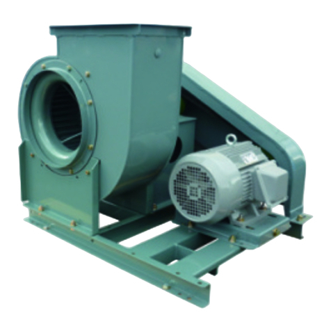
Teral CLFII-U User manual

Instruction Manual
Multiblade Fan with Silencer Box
Sirocco Fan with Silencer Box – Model CLFII-U / CLFIII-U / CLF5-U
Warning
Do not carry out operation, inspection or maintenance of the fan until you read this manual and understand
the content.
Keep this manual carefully at hand so that it can be consulted anytime when operating, inspecting or
maintaining the fan.
For contractors who carry out equipment work:
Please be sure to deliver this manual to user(s) who will carry out operation, inspection and maintenance of
the fan.
Teral Inc.

Limited warranties
1. In the event of failure or breakage under the proper use of the product during the warranty period,
equipment supplied by Teral Inc. (hereinafter referred to as TERAL) will be repaired or replaced
free of charge within the scope of the relevant part, provided that such failure or breakage is
attributable to inadequacy of the design or workmanship of the equipment.
2. The warranty mentioned in the above clause shall be only the mechanical warranty of the
defective part, and shall not cover any expenses or other damage arising from the failure or
breakage.
3. In the event of the following failures and breakage, the costs of the repairs shall be for the account
of the user.
(1) Failures and breakage attributable to equipment that was not delivered by TERAL
(2) Failures and breakage occurred after the expiration of the warranty period
(3) Failures and breakage caused by disasters or force majeure, such as fire, acts of God or
earthquakes
(4) Failures and breakage resulting from repairs or modifications made without the consent of
TERAL
(5) Failures and breakage occurred when parts other than those designated by TERAL are used
4. TERAL shall not be liable for the damage caused by incorrect or reckless use of the fan. Cost and
expenses incurred for sending engineer(s) in such a case shall be borne by the user.
5. If the cause of the failure is unclear, necessary actions shall be determined through mutual
consultation.
I

Purpose of this manual
The purpose of this manual is to provide the user with detailed information necessary to properly
operate, maintain and inspect the fan.
This manual contains the following information and is intended for persons experienced in the
operation of fans, or for those who have been trained by such experienced persons. Only
qualified personnel such as electrical engineers are allowed to carry out the electrical wiring
work.
Contents
Limited warranties .................................................................................................................................. I
Purpose of this manual.......................................................................................................................... II
Contents ................................................................................................................................................ II
1. Safety precautions
1.1 Types and meanings of warning terms................................................................................ 1-1
1.2 Safety precautions ............................................................................................................... 1-1
1.2.1 Precautions for placement and installation .................................................................. 1-1
1.2.2 Precautions for operation ............................................................................................. 1-1
1.2.3 Precautions for maintenance and inspection ............................................................... 1-2
1.3 Location of the warning labels ............................................................................................. 1-2
2. Configuration and overview of the fan
2.1 Structure and part names of the fan .................................................................................... 2-1
2.2 Specifications and accessories of the fan ........................................................................... 2-2
3. Placement and installation
3.1 Before using the fan............................................................................................................. 3-1
3.2 Precautions during transportation and storage ................................................................... 3-1
3.2.1 Precautions for transportation ...................................................................................... 3-1
3.2.2 Precautions for storage ................................................................................................ 3-2
3.3 Precautions for the location of installation........................................................................... 3-2
3.4 Foundation ........................................................................................................................... 3-2
3.5 Installation............................................................................................................................ 3-3
3.5.1 Floor-mounting type...................................................................................................... 3-3
3.5.2 Ceiling-mounting type................................................................................................... 3-4
3.6 Alignment ............................................................................................................................. 3-5
3.7 Precautions for connecting the ducts .................................................................................. 3-6
3.8 Precautions for wiring work..................................................................................................3-7
4. Preparation for operation
4.1 Points to be checked before test running ............................................................................ 4-1
4.1.1 Checking the electrical system..................................................................................... 4-1
4.1.2 Checking the fan system .............................................................................................. 4-1
5. Operation
5.1 Precautions when starting the fan ....................................................................................... 5-1
5.2 Precautions during the operation......................................................................................... 5-1
5.3 Precautions when stopping the fan ..................................................................................... 5-2
5.4 Precautions when stopping the use..................................................................................... 5-2
6. Maintenance and inspection
6.1 Daily inspection.................................................................................................................... 6-1
6.2 Periodic inspection............................................................................................................... 6-2
6.2.1 Refilling bearings with grease or replacing bearings ................................................... 6-3
6.2.2 Consumables................................................................................................................6-3
II

7. Troubleshooting
7.1 Troubleshooting ................................................................................................................... 7-1
8. Special accessories
8.1 Damper ................................................................................................................................ 8-1
8.2 Expansion joint..................................................................................................................... 8-1
8.3 Filter ..................................................................................................................................... 8-1
III

1. Safety precautions
1.1 Types and meanings of warning terms
This instruction manual divides precautions into the following four categories according to the
level of hazards (or the severity of the accident).
Be sure to understand the meanings of the following terms and comply with the content
(instructions) of the instruction manual.
Warning Term Meaning
Danger
Indicates an imminently hazardous situation. Failure to observe the
procedures or instructions will result in death or serious injury.
Warning
Indicates a potentially hazardous situation. Failure to observe the
procedures or instructions may result in death or serious injury.
Caution
Indicates a potentially hazardous situation. Failure to observe the
procedures or instructions will result in minor or moderate injury or cause
damage to equipment or devices.
Note Indicates information that is in particular to be noted or emphasized.
1.2 Safety precautions
1.2.1 Precautions for placement and installation
(1) Move and place the fan considering the center of gravity and weight.
(2) Install it according to the instruction manual.
(3) Do not install it anywhere exposed to direct flame or high temperature.
(4) Do not install it anywhere with high humidity, such as a bathroom.
(5) Do not install it in any places where toxic gases are produced from acids, alkalis, organic
solvent, paint or other substances or where corrosive gases are produced, for example in
machine shops or chemical plants.
(6) Install the outdoor air intake in a position far away from the exhaust vents of combustion gas,
etc.
(7) Be sure to install a ground fault interrupter to the main power.
(8) Only qualified personnel such as electrical engineers are allowed to carry out the electrical
wiring work. Before working, be sure to turn off the main power.
(9) Do not forcibly bend, pull, or pinch the motor connection cables. Failure to observe this may
result in an electric shock.
(10) Do not expose the motor to water.
If it gets wet, the resulting short circuit and/or insulation degradation of the electric circuit
may damage the fan.
(11) Install a protective wire mesh etc. to the open air intake.
1.2.2 Precautions for operation
(1) Before starting the fan, ensure that all the relevant workers are informed of the operation
and that there are no workers in the dangerous zone.
(2) Only those who are authorized by the site manager are allowed to operate the fan.
(3) Ensure to apply the rated voltage to the fan.
(4) When the fan is running, never touch any parts of the unit unless it is absolutely necessary.
1-1

(5) Do not put your fingers or other objects into the air intake or exhaust vents.
(6) Do not put your fingers or other objects into the opening of the motor. Failure to observe this
may cause an electric shock, injury, or fire.
(7) Do not place any objects around the air intake or exhaust vents of the fan.
(8) When the fan is running, do not open the inspection door of the silencer box.
(9) Remove any tools and other objects from the top of the fan before operation.
(10) Do not operate the fan if there are any defects or faulty parts.
1.2.3 Precautions for maintenance and inspection
(1) Maintenance and inspection must be carried out only by personnel who have been trained to
handle the fan.
(2) Before starting maintenance or inspection, ensure to inform the relevant personnel of the
operation.
(3) Before starting the maintenance or inspection work, ensure to stop the fan and turn off the
main power on the operation panel.
If you carry out the maintenance or inspection work with the power on, you may suffer an
electric shock and/or get injured by unexpected activation of the fan during the work.
(4) Consult Teral, Inc., or a service company before moving, repairing, or modifying the fan.
1.3 Location of the warning labels
The figure below shows the locations to which each warning label should be affixed. If these
labels become dirty and hard to read or if they are peeled off, replace with a new one.
Warning
Follow all warnings on the labels affixed to the unit and those in the
instruction manual.
Caution
Do not open the door
during operation, or
you may get injured.
Warning label d
Nameplate
Caution
Warning label c
ƕAsk specialized vendo
r
s for installation,
electrical work, and repairs.
ƕOnly personnel authorized by the
person in charge of machine
management are allowed to carry out
the maintenance and inspection work.
ƕRead the instruction manual thoroughly,
and follow the instructions.
1-2

2. Configuration and overview of the fan
2.1 Structure and part names of the fan
(1) Model CLFIII-U-RS and CLF5-U-RS
Built-in fan
(No. 3 and later)
(2) Model CLFII-U-RD
ౝ⬿ㅍ㘑ᯏ
Built-in fan
No. Part name No. Part name
cFan casing kIntake companion flange
dImpeller lDischarge companion flange
eAir intake {
11 Inspection opening
fMain shaft {
12 Silencer box base
gBearing case {
13 Vibration-proof rubber
hV-belt pulley {
14 Packing
iCommon base {
15 Cable
jSilencer box {
16 Sound absorbing material
2-1

2.2 Specifications and accessories of the fan
If you purchased a standard product, refer to the standard specifications in the following table.
For a custom-made product with special specifications, refer to the specifications including the
external dimensions drawing.
Caution
Do not use this product under any conditions other than those
provided in the specifications. Failure to observe this may cause an
electric shock, fire, and/or product failure.
(1) Standard specifications and special specifications
Clean air
Air 0qC to 40qC
Installation location Indoor (ambient temperature: 0qC to 40qC)
Installation method Floor-mounting / Ceiling-mounting
Totally enclosed type (0.4 kW and lower)
Type Dri
pp
roof t
yp
e
(
0.75 kW and hi
g
he
r
)
50Hz, 3 phases, 200V
Motor
Phase,
voltage 60Hz, 3 phases, 200/220V
Prime coating and interior coating: Anti-corrosive coating
Standard specifications
Painting Finish coating: Acrylic alkyd resin paint (Munsell
7.5BG5/1.5)
Position of inspection opening changed
Structural change Position of air intake changed
Totally-enclosed-fan-cooled type
Motor modifications Different voltage
Special
specifications
Paint changes Paint color specified
(2) Standard and special accessories
Standard accessories Special accessories
Companion flange Foundation bolt
Common base Intake mesh
Vibration-proof rubber Intake damper
V-belt pulley on the fan side Discharge damper
V-belt pulley on the motor side Intake filter
V-belt Connecting pipe
Expansion joint
2-2

3. Placement and installation
3.1 Before using the fan
When you receive the fan, check the following points first.
If there are any problems, contact the sales agent you purchased the product from.
Handle the motor according to the instruction manual of the motor.
Incorrect handling may result in an accident or failure.
(1) Check the nameplate to verify that the unit is the one you ordered.
(2) Check that the discharge direction, rotation direction, and power transmission methods are
as ordered.
(3) No part of the product is damaged during transportation.
(4) All fastening parts including bolts and nuts are securely tightened.
(5) All the accessories that you ordered have been delivered.
3.2 Precautions during transportation and storage
3.2.1 Precautions for transportation
Warning
•Do not get under the suspended fan. The fan may fall onto you.
•Ask a specialist company to move and place the fan in
consideration of the center of gravity and weight.
•Before hoisting the unit, refer to the catalogue or external
dimensions drawing etc. to confirm that the weight of the fan does
not exceed the load limit of the hoisting equipment.
Caution
Pay special attention to nails especially when opening a wooden box
that contains the unit, or you may get injured.
(1) To lift the fan, use the lifting eyes on the top of the silencer box.
(2) Use as long ropes and wires as possible so that the fan
can be lifted at an angle of 90° or less, which prevents
the fan from being deformed/damaged by the lifting load.
3-1

3.2.2 Precautions for storage
(1) Protect the unit so that rust does not form during storage before installation or assembly.
In particular, take measures to protect the silencer box against the entry of rainwater and
dust, for example by covering them with a vinyl sheet.
(2) Protect the motor connecting cables, electric components such as motors for indoor use,
and other parts against moisture.
3.3 Precautions for the location of installation
Install the fan in a place where the following conditions are satisfied:
(1) This fan is intended for indoor use. Install the fan in a place not exposed to the wind, rain,
etc. Furthermore, ensure to prevent rainwater from being sucked into the fan.
(2) Well-ventilated place with minimum exposure to dust or moisture
(3) Place with an ambient temperature of 0°C to 40°C
(4) Do not use the fan in a way that may cause condensation inside the machine at the
temperature and humidity of intake air on site.
(5) Place that is not accessible by unauthorized persons or that is impossible for them to
operate the fan at.
Take measures to prevent unauthorized persons from having access to the fan, for example
by installing a barrier.
(6) Place where the fan can be easily and safely inspected and repaired.
Ensure that there is enough space for assembly, disassembly, repairs and other operations
of the fan.
(7) If you install the fan indoors, ensure that the room has doors that are wide enough to allow
the fan to pass through.
3.4 Foundation
(1) The foundation must be strong enough to withstand the weight of the fan as well as the
vibration and load during its rotation.
(2) Ensure to maintain the levelness of the foundation concrete without any ground subsidence.
If the ground is soft, reinforce it by driving piles or through other methods.
(3) The weight of the foundation needs to be 2 to 4 times the total weight of the fan including the
motor.
(4) To prevent the transmission of vibrations, isolate the machine foundation from the posts and
floor of the building.
(5) To prevent the transmission of vibrations between two or more foundations, isolate each
foundation.
(6) In principle, make “boxed-out” holes in the foundation concrete, and fix the foundation bolts
into the holes during the installation of the fan. For the positions of the foundation bolt holes,
refer to the external dimensions drawing.
(7) To lay down a foundation on the second or higher floors—for example for installing building
equipment, locate the foundation as close to wall(s) as possible while aligning the
foundation with a beam.
3-2

3.5 Installation
3.5.1 Floor-mounting type
Carry out the following steps to install the fan using the foundation bolts (“boxed-out” method).
(Select appropriate steps according to each case, for example where foundation bolts are set in
place before installation.)
(1) Clean the surface of the foundation concrete, and check the levelness. Chipping may be
needed in some cases.
(2) Clean the foundation bolt holes and remove any dust or debris.
Although the foundation bolt holes need to be wet, they may not collect any water.
Thoroughly discharge water from the holes.
(3) As shown in the figure, place one flat liner and two tapered liners onto each foundation bolt
hole of the fan.
Use an auxiliary liner (3 mm or
thicker) as needed.
If the distance between
foundation bolts exceeds 1 m,
install an additional liner.
(4) Put the silencer box base on the
liners. Then pass each foundation
bolt through the foundation bolt
hole of the silencer box base to
allow the bolt to enter the
“boxed-out” hole.
To make the fan
earthquake-resistant, weld each
foundation bolt to reinforcing bars
of the foundation concrete.
(5) Adjust the position and height of
the fan using the tapered liners.
The levelness of the shaft should be 0.1 mm per 1 m, as a guide.
Auxiliary
Tapered
line
r
Flat liner
Foundation concrete
Mortar makeup
Silencer box base
(6) After sufficiently roughening the inner surface of each foundation bolt hole, fill the hole with
non-shrinkage mortar.
At that time, ensure that the foundation bolt is at right angles to the center of the hole.
(7) After the mortar has fully hardened, securely tighten the nut of each foundation bolt.
Be careful not to tighten the nuts unevenly.
Weld the liners to prevent them from shifting during operation.
(8) Fill the gap between the silencer box base and the foundation concrete with an adequate
amount of mortar to form a concrete structure.
(9) Check the mortar for shrinkage, cracks, or any other defects.
(10) To install vibration-proof springs, place them equally around the center of gravity of the fan
assembly unit.
(11) When the fan is installed and the ducts are connected, carry out the alignment work
described in the upcoming section 3.6.
3-3

3.5.2 Ceiling-mounting type
(1) Horizontally install the silencer box base onto the hang bolts mounted in the ceiling. Ensure
that the load is evenly distributed among all the bolts.
(2) The hang bolts and their mounting condition must be strong enough to sustain the load.
(3) After installation, install a locknut to each hang bolt to prevent them from loosening.
(4) To make the fan earthquake-resistant, securely install the fan onto a shaped steel frame fixed
to a building structure.
Silencer bo
x
Hang bolt
Silencer bo
x
base
Vibration-proo
f
rubbe
r
Common base
Double nut
3-4

3.6 Alignment
The fan is aligned at the factory before shipping, but should be realigned after installation.
Warning
To carry out this alignment work, the inspection door of the silencer
box must be opened. However, be sure to close the door before
starting the fan.
If you run the fan with the door open, the door may close suddenly or
part of your body may get sucked in the machinery, thus causing
injury.
Caution
Incorrect alignment may damage the equipment, or cause vibrations
and noise. Align the fan correctly.
(1) Place a ruler or a piano wire onto the outer surfaces
of the V-belt pulleys on both the fan and motor sides,
and check and adjust it so that the surfaces of the
pulleys are on a straight line (i.e. the axes of the
pulleys are in parallel to each other).
(2) Since V-belts tend to stretch at the early stages of
its use, ensure to readjust it in several days of use.
Use the slide base of the motor to adjust the tension
of the V-belt.
[Procedure]
- Determine the standard deflection į: 0.016Ɛ.
(Ɛ: Distance between pulleys)
- Then use a tension meter to give the standard deflection (įmm) in the middle of the V-belt.
Re-tension the belt (or adjust the tension) so that the deflection load at that time becomes the
corresponding value in the following table.
Ruler or piano wire
Make them parallel
V-belt pulley
Moto
r
Fan
Note
A too loose V-belt may slip or come off.
A too tight V-belt may reduce the service life of the bearings of the
fan and motor.
Deflection load Td for each V-belt type and small pulley OD
V-belt
type
Range of small
pulley outside
diameter (mm)
Deflection load of new
belt
N/belt (kgf/belt)
Deflection load after
re-tension
N/belt (kgf/belt)
A
65
81
91
106
-
-
-
-
80
90
105
9.8 (1.0)
11.8 (1.2)
13.7 (1.4)
15.7 (1.6)
7.8 (0.8)
8.8 (0.9)
10.8 (1.1)
11.8 (1.2)
B
115
136
161
-
-
-
135
160
17.7 (1.8)
22.6 (2.3)
24.5 (2.5)
13.7 (1.4)
17.7 (1.8)
18.6 (1.9)
C
175
206
256
-
-
-
205
255
35.3 (3.6)
42.2 (4.3)
50.0 (5.1)
27.5 (2.8)
32.4 (3.3)
38.2 (3.9)
3V
67
91
116
151
-
-
-
-
90
115
150
300
21.6 (2.2)
25.5 (2.6)
29.4 (3.0)
33.3 (3.4)
17.7 (1.8)
19.6 (2.0)
22.6 (2.3)
25.5 (2.6)
5V
180
231
311
-
-
-
230
310
400
74.5 (7.6)
90.2 (9.2)
105.9 (10.8)
57.9 (5.9)
69.6 (7.1)
82.4 (8.4)
The values in ( ) are expressed in the traditional unit system and shown for
reference only.
Tension meter
3-5

3.7 Precautions for connecting the ducts
Caution
Ensure to prevent any load of the ducts from acting on the fan.
Failure to observe this may cause a failure, damage, and/or vibration.
(1) In order to prevent transmission of vibration and noise to the outside, connect the fan’s flange
and the duct using an expansion joint. Note that giving too much deflection to the expansion
joint may cause pressure loss.
(2) Before connecting the ducts, check inside the ducts and fan, and remove any foreign matter,
such as waste cloth and tools.
(3) In general, unexpected pressure loss may occur due to the connection to (a) ducts that are
much smaller than the port diameter of the fan, (b) ducts with a series of bends, or (c) ducts
with bends just before or after the connection to the fan.
(4) If the opening area just in front of the air intake of the silencer box is significantly
reduced—for example by blocking the area with an iron plate, the air flow rate around the air
intake rises, which may cause damage to the sound absorbing material lined inside.
Warning
If the air intake of the silencer box is open, be sure to install a
protective wire mesh on it.
(5) To prevent foreign matter from being sucked into each place, install a protective wire mesh to
the duct inlet or the air intake of fan where air is sucked directly.
If dust or water is expected to get inside the fan or the silencer box, install a filter to protect
against it.
(6) If necessary, provide a damper for air volume control.
Do not install the damper close to the air intake of the silencer box.
Note
The gap between the air intake of the silencer box and the wall
should be equal to or larger than the long side of the air intake of the
silencer box.
3-6

3.8 Precautions for wiring work
Warning
Use high-quality wiring equipment and devices, and carry out wiring
work safely and securely according to the technical standards for
electrical facilities, as well as the indoor wiring regulations.
Only qualified personnel such as licensed electrical engineers are
allowed to carry out electrical wiring work.
Unqualified persons are prohibited by law from performing wiring
work and it is very dangerous.
(1) Be sure to install a ground fault interrupter and an overload protection device on the primary
power side of the fan.
(2) Be sure to install a ground wire to prevent an electric shock.
•Do not connect the ground wire to gas pipes, water pipes, lightening arresters, or ground
wires for telephone.
Warning
It is prohibited by law to perform incomplete wiring work, which
exposes personnel to a great danger.
(3) The cable has been connected to the terminal in the motor terminal box, and drawn out of
the silencer box.
Standard connections are direct-start for 7.5kW or smaller motors and Star-Delta starting for
11kW or larger motors.
Connect the cable and power supply according to the instruction manual of the motor.
Warning
Do not forcibly bend the motor connecting cable, run it into the fan, or
pull it. Failure to observe this may result in an electric shock.
(4) Control the fluctuation of the voltage within ±10% of the rated voltage, and the frequency
within ±5% of the rated frequency. If the product is not used within the range, it may break
down.
(5) Before running the fan, check the following points again:
cAn appropriate fuse (ground fault interrupter) is installed.
dWiring is correct.
eThe product is securely connected to a ground.
fNone of the three terminals of the motor has come loose or is disconnected.
Keep in mind that running with connection of only 2 terminals results in open-phase
operation, which may cause motor burnout.
3-7

4. Preparation for operation
4.1 Points to be checked before test running
4.1.1 Checking the electrical system
(1) Check that the fan is correctly wired.
(2) Check that the terminals are securely connected.
(3) Check that the equipment is securely grounded.
(4) Check that the settings of the overload protection device match the rated current value of
the motor being used. The rated current value is indicated on the motor nameplate.
4.1.2 Checking the fan system
(1) Check that no water collects in the silencer box or the fan and that no foreign objects or
materials such as tools are left inside.
(2) Check that all the connections on the foundation bolts, fan, accessories and pipe joints are
securely tightened.
(3) Check that the dampers and valves can fully open and close, and that they operate
normally.
(4) Check the alignment of V-belt pulleys and the tension of V-belt.
Warning
Always turn OFF the main power before rotating the fan by hand.
(5) Rotate the fan by hand or by inching a motor to check that it can rotate smoothly without any
internal obstructions.
(6) Place an operator in advance so that the fan can be turned OFF immediately after the
instructions of the person in charge of the operation.
Warning
Do not operate the fan if it is not running properly, for example if it is
making a strange noise. Contact a specialist company or the service
company designated by the manufacturer.
4-1

5. Operation
5.1 Precautions when starting the fan
Warning
Be sure to close the inspection door of the silencer box before
operating the fan.
(1) Close the damper and turn the unit ON and OFF once or twice to confirm that the unit is
operating normally without any unusual noise or vibrations. Moreover, check the rotation
direction of the fan at that time.
If the fan rotates in the reverse direction, swap two of the three wires of the power cable.
Warning
Be sure to turn off the main power before changing the wiring of the
fan.
(2) Turn on the power, and watch the unit closely until it reaches full speed.
At that time, carefully check for unusual noise, vibrations, current, or any other abnormal
condition.
(3) Start the continuous operation, and gradually open the damper.
In order to check the condition of each part, keep the fan running at a low flow rate (light
load) for 20 to 30 minutes.
At that time, ensure that the fan does not run at a rate where surging may occur.
(4) Gradually open the damper until the fan reaches the full load operation.
Keep it running under the condition for 1 to 3 hours, and check the temperature, vibrations
and noise at each section of the fan.
In addition, check that the motor current value is normal.
Note that the (electrical) current value becomes higher when the temperature of flowing air
is lower than the room temperature.
The bearing temperature may become slightly higher than usual for about one to two hours
after the start of operation. If there are no errors in the machine, however, the temperature
stabilizes afterwards.
5.2 Precautions during the operation
(1) Frequently starting and stopping the fan quickly damages it. Use the following values as a
guide for the frequency of starting the fan.
Motor output Startup frequency
7.5kW or less Up to 6 times an hour
11kW to 22kW Up to 4 times an hour
Warning
In the event of a power failure, be sure to turn off the main power.
Otherwise, when the power is restored, the fan suddenly starts, and
it is dangerous.
5-1

5.3 Precautions when stopping the fan
(1) To stop the fan, gradually close the damper to the full and then turn OFF the power switch.
5.4 Precautions when stopping the use
Warning
When you leave the fan unused for a long period of time, be sure to
turn off the main power.
(1) When you leave the fan unused for a long period of time, apply appropriate anti-corrosive
agent to the areas prone to rust.
(2) Protect the motor and other electrical devices against moisture.
(3) Remove the V-belt before storing the fan.
(4) Cover the bearing with a vinyl sheet or other material to prevent contact with outside air and
entry of dust.
(5) Before you run the fan after a long time of nonuse, inspect each part, and refill the bearing
with grease or replace the bearing. (Refer to 6.2.1 "Refilling bearings with grease and
replacing bearings.")
5-2

6. Maintenance and inspection
6.1 Daily inspection
(1) Check the vibration, noise, current value, etc. of the fan.
If there is any unusual condition, it may be a sign of failure; therefore, take the appropriate
measures as soon as possible.
For this purpose, it is recommended to keep an operation log.
Warning
The main shaft, V-belt pulley, and V-belt are rotating during
operation. Be extra careful not to get your clothes etc. caught in
these parts.
(2) If strong vibrations occur, stop
the operation and inspect the
V-belt alignment, duct
connections, tightening of the
installation bolts and foundation
bolts, and check for
accumulation of dust on the
impeller and damage to the
bearings.
If the vibration is within the range
specified as "Good" in JIS B
8330, it is considered normal
(see the figure on the right).
If a vibration-proof device is
installed on the fan, vibration of
the fan itself becomes slightly
stronger although the vibration is
not transmitted to the foundation.
In such a case, a vibration lower
than the broken line is
considered normal.
(3) In addition to vibrations, noise is
an important factor in judging the
operating condition.
If you hear a metallic sound
possibly made by contact with
the rotor, stop the operation
immediately.
Continuous noise of air flowing inside the casing (such as “Goooo”, “Zaaaa”) is normal;
however, discontinuous noise (such as “ZaaZaa”, “WonWon”) is caused by surging. An
appropriate measure is required in the latter case, for example by changing the damper
opening.
(On the bearing housing)
a - Total amplitude (ȝm)
n - Rotation (mim-
1
)
Acceptable vibration range
Good
Excellent
A
cceptable
Unacceptable
With vibration isolator
10mm/s
(4) Bearings generate noise even in normal condition.
Although it is difficult to identify an abnormal noise because bearings produce complicated
noise, learn about the noises thoroughly to prevent an accident.
6-1

Normal noise produced at bearings
Type of noise Normal noise
Race noise It is a continuous noise without any sudden change. This noise is
generated when a ball rolls on the race surface.
Roller dropping
noise
It is a cyclic noise. When load applies in the radial direction (which is
mostly the case), a ball is restricted by the load applied, and then released
to be free, repeatedly. This noise is generated when the ball comes to the
boundary. It occurs mostly with low speed bearings, but is harmless.
Retainer noise
A retainer maintains the relative position of the ball. There is a small
clearance between the retainer and the outer ring, which allows the
retainer to rotate; however, a continuous noise is generated when the
retainer contacts the outer ring occasionally. It is a slightly annoying noise,
but cannot be eliminated easily. It occurs mostly with low speed bearings,
but is harmless.
Abnormal noise produced at bearings
Type of noise Abnormal noise
Contaminant noise
Dust may get inside a bearing due to careless handling of grease or for
other reasons. In such a case, the bearing makes an irregular grinding
noise.
Replace the old grease with new grease.
Damage noise
Any damage on the ball may generate a discontinuous irregular noise. Any
damage on the race surface of the inner or outer ring may generate a
continuous noise. If the noise is faint or insignificant, the bearing may still
be used after being refilled with grease. If the nose becomes serious,
replace the bearing.
Rust noise The same problem described in the damage noise occurs. If the noise
becomes serious, replace with a new bearing.
Scraping noise
It is a scraping noise without a regular cycle. This noise is generated when
sliding occurs or lubrication is not effective between the ball and ring or
between the ball and retainer. Replace the grease with high-quality grease.
6.2 Periodic inspection
Warning
Before carrying out the inspection of the fan, be sure to turn off the
main power. Otherwise the fan may suddenly start up during
automatic operation etc., exposing personnel to great danger.
Carry out the periodic inspection at least once a year.
The periodic inspection items include the following points, in addition to the daily inspection
items.
(1) Refill the bearings with grease.
(2) Inspect the alignment and V-belt.
Inspect the V-belt for wear or damage, and check the tension. If necessary, replace or
re-tension the V-belt.
(3) Inspect the play at the connection between the impeller boss and the main shaft.
(4) Inspect the impeller and the main shaft for corrosion and wear.
(5) Clean the inside of the fan, and apply anti-corrosive agent or otherwise make repairs.
6-2
This manual suits for next models
2
Table of contents
Other Teral Fan manuals
Popular Fan manuals by other brands
Tecnosystemi
Tecnosystemi AIRPUR EVO PLUS 12500020 user manual

Fanimation
Fanimation Fitzgerald OF6320 Series owner's manual
Russell Hobbs
Russell Hobbs SCANDI operating manual
Hunter
Hunter 53310 installation manual
Modern Forms
Modern Forms Slim installation instructions
motortronics
motortronics VMX-agility VMX-AGY-031 installation guide
