⇷⇳∑∄⇌∙⇮ࡸ
ٳᢿદ˺⇵∙⇯∑
ӕৢᛟଢ
Panel-Mounted
External Operating Handle
Instruction Manual
Type: TPHP63S
ᮏᶵࡣ㸪ẚ㍑ⓗዟ⾜ࡢ࠶ࡿ࣮ࣔࢱ࣮ࢥࣥࢺ࣮ࣟࣝࢭࣥࢱ࣮ࡸ㓄㟁┙ෆ⤌㎸ࢇ
ࡔ㐽᩿ჾࢆ┙እࡽᡭື࡛᧯సࡍࡿ⨨࡛ࡍࠋ
This device allows the breaker installed in comparatively deep motor control center or
switchboard to be operated manually without the need for opening the panel of the motor control
center or switchboard.
ᮏ᭩ࡣ㸪ࡈ⏝࡞ࡿ᪉ࡢ࠾ᡭඖ࡛ษಖ⟶ୗࡉ࠸ࠋᮏ᭩グ㍕ࡢ࡞࠸ྲྀᢅ
࠸㸪ཬࡧㄗࡗࡓྲྀᢅ࠸ࡼࡾ⏕ࡌࡿᦆᐖ㛵ࡋ࡚㸪ᘢ♫ࡣ㈐௵ࢆ㈇࠸ࡲࡏࢇࠋ
Please retain this manual for future reference. The Manufacturer assumes no responsibility for
damages resulting from non-application or incorrect application of the instructions provided herein.
2G1438SABᵆKRB-0953bᵇ
⇵∙⇯∑ښᘍ∝ᢚૺ֥ӕ˄ↀ૾Ӽ٭ᙲ
The Handle Depth/ The Mounting Direction Changing Procedure
࣭㔠ᒓษ᩿㒊ࡣ㜵㗵ฎ⨨ࢆࡋ࡚ୗࡉ࠸ࠋ
࣭Perform the anti-rust treatment to the metal section.
ϋܾཋɟᚁPackaged Items
ࣁࣥࢻࣝࣘࢽࢵࢺ ྲྀᯈ 㜵ሻࣃࢵ࢟ࣥ㸦࢜ࣉࢩࣙࣥ㸧
Handle unit Mounting plate Gasket for dust protection optional
ゅࢩࣕࣇࢺ ྲྀᯈ㸦࢜ࣉࢩࣙࣥ㸪IP65 ᵝࡢሙྜ㸧
Square shaft Mounting plate (optional, for specification of IP65)
ࢳ࣮ࣗࣈ
Rigid tube
ࡉࡽࡡࡌ㯮M414- 4pcs.
Flat head screws
ࢩࣕࣇࢺࢧ࣏࣮ࢺ
Shaft support
black
᧯సࣘࢽࢵࢺ࣮࢟㸦࢜ࣉࢩࣙࣥ㸧
Operation unit Key optional
࣭ഛ⪃ḍղ ճグ㍕ࡢ࠶ࡿሙྜ㸪ࢩࣕࣇࢺࢧ࣏࣮ࢺࡀせ࡞ࡿࡓࡵ
ղ ճࡢฎ⨨ࢆ⾜ࡗ࡚ୗࡉ࠸ࠋ
࣭ղ and ճin the Remarks column mean without shaft support.
࣭Then must be followed the steps ղand ճas shown in the figures above.
ᢘဇᢚૺ֥࢟ࡸApplicable Breaker Types
ࣁࣥࢻࣝᙧᘧ
Handle type
㐺⏝㐽᩿ჾᙧᘧ
Applicable breaker types
TPHP63S
*1:
□□
=SFは除く
࣏ᙲ↗↙↺φAssembly Tools
4.550 No.2
ܤμɥ↝ↃදSafety Notices
ᕤ㸪⏝㸪ಖᏲ࣭Ⅼ᳨ࡢ๓㸪ᚲࡎᮏ᭩ࡑࡢࡢᒓ᭩㢮ࢆ࠾ㄞࡳ㡬ࡁ㸪
ᶵჾࡢ▱㆑㸪Ᏻࡢሗ㸪ཬࡧὀព㡯ࡢ࡚⩦⇍ࡋ࡚ࡽ࠾ྲྀᢅ࠸ୗࡉ࠸ࠋ
ᮏ᭩࡛ࡣ㸪Ᏻὀព㡯ࡢࣛࣥࢡࢆࠕ ༴㝤ࠖ㸪ࠕ ὀពࠖ༊ศࡋ࡚࠸ࡲࡍࠋ
༴㝤㸸
ྲྀᢅ࠸ࢆㄗࡗࡓሙྜ㸪༴㝤࡞≧ἣࡀ㉳ࡇࡾ࠼࡚㸪Ṛஸࡲࡓࡣ㔜യࢆཷ
ࡅࡿྍ⬟ᛶࡀᐃࡉࢀࡿሙྜࠋ
ὀព㸸
ྲྀᢅ࠸ࢆㄗࡗࡓሙྜ㸪༴㝤࡞≧ἣࡀ㉳ࡇࡾ࠼࡚㸪୰⛬ᗘࡢയᐖࡸ㍍യ
ࢆཷࡅࡿྍ⬟ᛶࡀᐃࡉࢀࡿሙྜཬࡧ≀ⓗᦆᐖࡢࡳࡀᐃࡉࢀࡿሙྜࠋ
࡞࠾㸪ࠕ ὀពࠖグ㍕ࡋࡓ㡯࡛ࡶ㸪≧ἣࡼࡗ࡚ࡣ㔜࡞⤖ᯝ⤖ࡧࡘࡃ
ྍ⬟ᛶࡀ࠶ࡾࡲࡍࠋ࠸ࡎࢀࡶ㔜せ࡞ෆᐜ࡛ࡍࡢ࡛㸪ᚲࡎᏲࡗ࡚ୗࡉ࠸ࠋ
Be sure to read these Instructions and other associated documents accompanying the product
thoro- ughly to be familiarize yourself with the product handling, safety information, and all other
precautions before mounting, using, servicing, or inspecting the product. In these Instructions,
safety notices are divided into " Warning" and " Caution" according to the hazard level:
Warning :
A warning notice with this symbol indicates that neglecting the suggested procedure
or practice could be fatal or result in serious personal injury.
Caution
:
A caution notice with this symbol indicates that neglecting the suggested procedure or
practice could result in moderate or slight personal injury and/or property damage.
Note that failing to observe caution notices could result in serious injury/damage in some situations.
Because safety notices contain important information, be sure to read and observe them.
༴㝤 Warning
ڦ⏝ୖࡢࡈὀពOperation Precautions
ە㟁➃Ꮚ㒊ゐࢀ࡞࠸࡛ୗࡉ࠸ࠋឤ㟁ࡢ࠾ࡑࢀࡀ࠶ࡾࡲࡍࠋ
Never touch live terminals. Doing so may result in electric shock.
ὀព Caution
ڦᕤୖࡢࡈὀពInstallation Precautions
ە㟁Ẽᕤࡣ㸪᭷㈨᱁⪅㸦㟁Ẽᕤኈ㸧ࡀ⾜ࡗ࡚ୗࡉ࠸ࠋ
Electrical work should only be undertaken by suitably qualified persons.
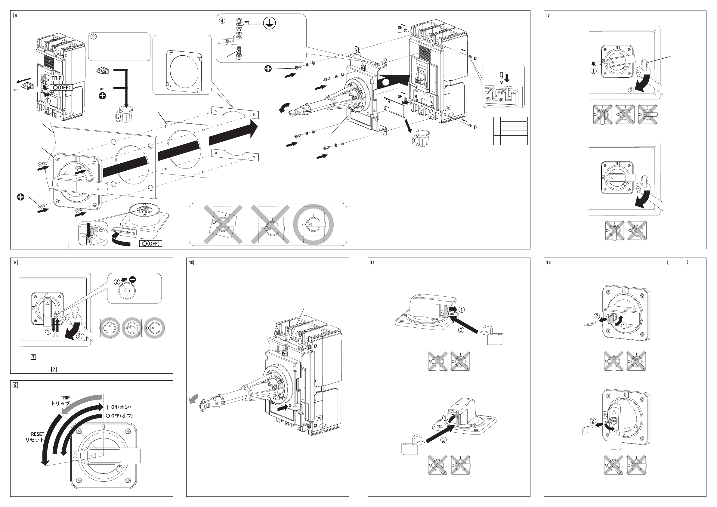
ەᕤసᴗࡣ㸪ୖ㐽᩿ჾ࡞ࢆۑ㸦OFF㸧ࡋ㸪㟁ࡋ࡚࠸࡞࠸ࡇࢆ
☜ㄆࡋ࡚⾜ࡗ࡚ୗࡉ࠸㹿ឤ㟁ࡢ࠾ࡑࢀࡀ࠶ࡾࡲࡍࠋ
Prior to commencing any work on the product, open an upstream circuit breaker or isolator
to ensure that no voltage is applied to the product. Otherwise, electrical shock may result.
ە㓄㟁┙ࡢࣃࢿࣝࡢᅛᐃࡣ㸪ᮏᶵࡢࣃࢿࣝࣟࢵࢡࡣูᅛᐃ㔠ලࢆࡈ
⏝ពୗࡉ࠸ࠋᮏᶵࡢࡳ࡛ࡢࣃࢿࣝࡢᅛᐃࡣ㸪◚ᦆࡢཎᅉ࡞ࡾࡲࡍࠋ
To remain the switchboard panel closed securely, use appropriate hardware in addition to
the panel lock of the handle. Using the panel lock only may result in damage to the
switchboard panel.
ڦ⏝ୖࡢࡈὀពOperation Precautions
ە㐽᩿ჾࡀ⮬ືⓗࢺࣜࢵࣉ㸦㐽᩿㸧ࡋࡓሙྜࡣ㸪ཎᅉࢆྲྀࡾ㝖࠸࡚ࡽ
ࣁࣥࢻࣝࢆ㹺㸦ON㸧ࡋ࡚ୗࡉ࠸ࠋ㟁ὶ㸦▷⤡㟁ὶ㸧ࢆ㐽᩿ࡋࡓሙྜ
ࡣ㸪㐽᩿ჾࢆⅬ᳨ࡋ࡚ୗࡉ࠸ࠋⅆ⅏ࡢ࠾ࡑࢀࡀ࠶ࡾࡲࡍࠋ
When the breaker trips open automatically, remove the cause, then return the handle to
the |(ON) position. Should a fault be interrupted, the breaker must be inspected.
Otherwise, a fire may result.
ە᧯సࣀࣈ㐣࡞Ⲵ㔜ࢆຍ࠼࡞࠸࡛ୗࡉ࠸ࠋᦆയࡢཎᅉ࡞ࡾࡲࡍࠋ
Do not apply excessive force to the operating knob. Otherwise, damage may occur.
㸸ୗ⾲ࡼࡾ㸪ኚ᭦ࡍࡿ㐽᩿ჾྲྀࡅ᪉ྥᑐᛂࡋࡓゅࢩࣕࣇࢺࡣࡵ㎸ࡳ
⨨ࢆ㑅ࡧ㸪ࡣࡵ㎸ࡳࡲࡍࠋ
Referring to the table below, install the square shaft in the position matched to the
change in breaker mounting direction.
ゅࢩࣕࣇࢺࡣࡵ㎸ࡳ⨨Square shaft installation positions
㐽᩿ჾ
ྲྀࡅ᪉ྥ
Mounting
direction
ୖ㟁※౪⤥ᙧ
Upper power suppl
t
pe
ᕥ㟁※౪⤥ᙧ
Left power supply
type
ྑ㟁※౪⤥ᙧ
Ri
ht power suppl
type
ゅࢩࣕࣇࢺ
ࡣࡵ㎸ࡳ⨨
Square shaft
installation
positions ᶆ‽Default
A
C
B
C
B
PS400-
ڧڧ
, PS630-
ڧڧ
, PH400-
ڧڧ
, PH630-
ڧڧ
,
P400
ڧ
, P630
ڧ
PS400-
ڧڧ
,
PS630-
ڧڧ
,
PH400-
ڧڧ
,
PH630-
ڧڧ
,
P400
ڧ
, P630
ڧ
㐺⏝㐽᩿ᙧᘧ
Applicable breaker types A 䛊mm䛋B 䛊mm䛋C 䛊mm䛋䝅䝱䝣䝖ᙧᘧ
Applicable shaft types Shaft support
䝅䝱䝣䝖䝃䝫䞊䝖᭷↓
ഛ⪃
remarks
270㹼310
311㹼340
341㹼410
411㹼510
511㹼610
T2PS401
T2PS403
T2PS404
A-258
A-162.5
ࠐ
T2PS402
䐠㻌䐡
A-330
䇷
࡞ࡡࡌM516- 4pcs.
Pan head screws
䝘䝑䝖䝩䝹䝎䞊㻔3ᴟ⏝㻕 4pcs.
Nut holder (for 3 poles)
䝘䝑䝖䝩䝹䝎䞊㻔㻠ᴟഃ⏝㻕㻌2pcs.
Nut holder (for 4 pole side)
M412- 4pcs.
No.2
3.6 - 4.4 N㺃m
3.6 - 4.4 N㺃m
〒547-0002
大阪市平野区加美東6
–
13
–
47
TEL 06
–
6791
–
2756
FAX 0 6
–
6791
–
2732
https://www.terasaki.co.jp
kiki-info@terasaki.co.jp
6-13-47 Kamihigashi, Hiranoku, Osaka
547-0002, Japan
TEL +81-6-6791-2763
FAX +81-6-6791-2732
https://www.terasaki.co.jp