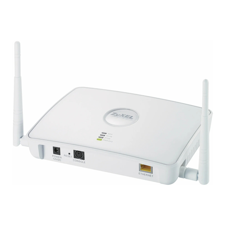
Terayon TA-102 Installation instructions

Terayon Communication Systems
TA 102/202 eMTA
Technical Support Guide
Part No. 8500276 Rev B
December 2004

ii TA 102/202 Technical Support Guide
Contacting Terayon Communication Systems
You can contact Terayon Communication Systems as follows:
•Telephone: (888) 783-7296 (888-7-Terayon) or 408-235-5823, 24 hours a day, 7 days a week
•Postal mail:
Terayon Communication Systems
4988 Great America Parkway
Santa Clara, CA 95054, U.S.A.
•e-mail: [email protected] (for technical support)
•Feedback and suggestions to Technical Publications Group:
techpubs@terayon.com
•Worldwide Web: http://www.terayon.com
European Support
•Telephone: 32.1.638.4772
•email: [email protected] (for technical support)
Asia/Pacific Support
•Telephone: 852.2111.5980
•email: apsupport@terayon.com (for technical support)

TA 102/202 Technical Support Guide iii
Contents
Chapter Preface
Why Use This Guide? . . . . . . . . . . . . . . . . . . . . . . . . . . . . . . . . . . . . . . . . . . . . . .vii
How To Use This Guide . . . . . . . . . . . . . . . . . . . . . . . . . . . . . . . . . . . . . . . . . . . . .vii
About This Guide . . . . . . . . . . . . . . . . . . . . . . . . . . . . . . . . . . . . . . . . . . . . . . . . . .vii
Organization. . . . . . . . . . . . . . . . . . . . . . . . . . . . . . . . . . . . . . . . . . . . . . . . . .vii
Icons Used in This Guide . . . . . . . . . . . . . . . . . . . . . . . . . . . . . . . . . . . . . . . . . . . viii
Chapter 1 Overview
What is an Embedded MTA? . . . . . . . . . . . . . . . . . . . . . . . . . . . . . . . . . . . . . . . .1-2
MTA. . . . . . . . . . . . . . . . . . . . . . . . . . . . . . . . . . . . . . . . . . . . . . . . . . . .1-2
Cable Modem . . . . . . . . . . . . . . . . . . . . . . . . . . . . . . . . . . . . . . . . . . . .1-2
The TA 102/202 eMTA at a Glance . . . . . . . . . . . . . . . . . . . . . . . . . . . . . . . . . . . 1-3
Features. . . . . . . . . . . . . . . . . . . . . . . . . . . . . . . . . . . . . . . . . . . . . . . . . . . .1-3
Hardware Architecture . . . . . . . . . . . . . . . . . . . . . . . . . . . . . . . . . . . . . . . . . . . . .1-4
TA 102/202 eMTA Interfaces . . . . . . . . . . . . . . . . . . . . . . . . . . . . . . . . . . . .1-5
RF Interface. . . . . . . . . . . . . . . . . . . . . . . . . . . . . . . . . . . . . . . . . . . . . . 1-5
High Speed Data Interfaces . . . . . . . . . . . . . . . . . . . . . . . . . . . . . . . . .1-6
POTS Interface . . . . . . . . . . . . . . . . . . . . . . . . . . . . . . . . . . . . . . . . . . .1-6
Speech Codec . . . . . . . . . . . . . . . . . . . . . . . . . . . . . . . . . . . . . . . . . . . . . . .1-7
MIB Support . . . . . . . . . . . . . . . . . . . . . . . . . . . . . . . . . . . . . . . . . . . . . . . . . . . . .1-8
Security . . . . . . . . . . . . . . . . . . . . . . . . . . . . . . . . . . . . . . . . . . . . . . . . . . . . . . . .1-9
Quality of Service (QoS) . . . . . . . . . . . . . . . . . . . . . . . . . . . . . . . . . . . . . . . . . . . .1-9
Standards Compliancy . . . . . . . . . . . . . . . . . . . . . . . . . . . . . . . . . . . . . . . . . . . . . 1-9
DOCSIS 2.0/Euro-DOCSIS 1.1 . . . . . . . . . . . . . . . . . . . . . . . . . . . . . . . . . . 1-9
PacketCable. . . . . . . . . . . . . . . . . . . . . . . . . . . . . . . . . . . . . . . . . . . . . . . . 1-10
Chapter 2 Installation
Getting Started . . . . . . . . . . . . . . . . . . . . . . . . . . . . . . . . . . . . . . . . . . . . . . . . . . . 2-2
Package Contents . . . . . . . . . . . . . . . . . . . . . . . . . . . . . . . . . . . . . . . . . . . .2-2
Terayon TA-102 or TA-202 MTA Modem Package Contents . . . . . . . . 2-2
System Requirements . . . . . . . . . . . . . . . . . . . . . . . . . . . . . . . . . . . . . . . . .2-2
MTA Installation . . . . . . . . . . . . . . . . . . . . . . . . . . . . . . . . . . . . . . . . . . . . . . . . . .2-4
What the Customer Will Need . . . . . . . . . . . . . . . . . . . . . . . . . . . . . . . . . . . 2-4
Modem Connectors. . . . . . . . . . . . . . . . . . . . . . . . . . . . . . . . . . . . . . . . . . .2-5
CATV Coax Cable to TA-102/202 eMTA . . . . . . . . . . . . . . . . . . . . . . . . . . . 2-6
Connecting the Power Adapter to the TA-102/202 eMTA . . . . . . . . . . . . . .2-7
Connecting the TA-102/202 eMTA to a PC . . . . . . . . . . . . . . . . . . . . . . . . .2-9
Connecting the 10/100 Base-T Ethernet Cable. . . . . . . . . . . . . . . . . . .2-9
Connecting the USB Cable . . . . . . . . . . . . . . . . . . . . . . . . . . . . . . . . .2-11
Connecting A Telephone to the TA-102/202 eMTA . . . . . . . . . . . . . . . . . .2-13

iv TA 102/202 Technical Support Guide
TA-102/202 eMTA Start Up . . . . . . . . . . . . . . . . . . . . . . . . . . . . . . . . . . . .2-14
Front Panel Indicators . . . . . . . . . . . . . . . . . . . . . . . . . . . . . . . . . . . . . . . . 2-15
BU 802 Battery Backup Unit Installation . . . . . . . . . . . . . . . . . . . . . . . . . . . . . . 2-16
Readying the Installation Site. . . . . . . . . . . . . . . . . . . . . . . . . . . . . . . . . . . 2-18
Unpacking the BU 802 Battery Backup Unit. . . . . . . . . . . . . . . . . . . . . . . .2-18
Battery Installation . . . . . . . . . . . . . . . . . . . . . . . . . . . . . . . . . . . . . . . . . . . 2-19
eMTA/BBU Mating . . . . . . . . . . . . . . . . . . . . . . . . . . . . . . . . . . . . . . . . . . . 2-21
BU 802 Wall Mounting . . . . . . . . . . . . . . . . . . . . . . . . . . . . . . . . . . . . . . . . 2-22
Power Up and Check . . . . . . . . . . . . . . . . . . . . . . . . . . . . . . . . . . . . . . . . . 2-24
Battery Status LED. . . . . . . . . . . . . . . . . . . . . . . . . . . . . . . . . . . . . . . . . . . 2-25
BU 802 Specifications . . . . . . . . . . . . . . . . . . . . . . . . . . . . . . . . . . . . . . . .2-27
Chapter 3 Troubleshooting
Troubleshooting Summary . . . . . . . . . . . . . . . . . . . . . . . . . . . . . . . . . . . . . . . . . . 3-3
Typical End User Problems and Solutions . . . . . . . . . . . . . . . . . . . . . . . . . . . . . . 3-4
Problem: . . . . . . . . . . . . . . . . . . . . . . . . . . . . . . . . . . . . . . . . . . . . . . . .3-4
Possible Solution: . . . . . . . . . . . . . . . . . . . . . . . . . . . . . . . . . . . . . . . . . 3-4
Problem: . . . . . . . . . . . . . . . . . . . . . . . . . . . . . . . . . . . . . . . . . . . . . . . .3-4
Possible Solution: . . . . . . . . . . . . . . . . . . . . . . . . . . . . . . . . . . . . . . . . . 3-4
Problem: . . . . . . . . . . . . . . . . . . . . . . . . . . . . . . . . . . . . . . . . . . . . . . . .3-5
Possible Solution: . . . . . . . . . . . . . . . . . . . . . . . . . . . . . . . . . . . . . . . . . 3-5
Problem: . . . . . . . . . . . . . . . . . . . . . . . . . . . . . . . . . . . . . . . . . . . . . . . .3-6
Possible Solution: . . . . . . . . . . . . . . . . . . . . . . . . . . . . . . . . . . . . . . . . . 3-6
Problem: . . . . . . . . . . . . . . . . . . . . . . . . . . . . . . . . . . . . . . . . . . . . . . . .3-6
Possible Solution: . . . . . . . . . . . . . . . . . . . . . . . . . . . . . . . . . . . . . . . . . 3-6
Problem: . . . . . . . . . . . . . . . . . . . . . . . . . . . . . . . . . . . . . . . . . . . . . . . .3-7
Possible Solution: . . . . . . . . . . . . . . . . . . . . . . . . . . . . . . . . . . . . . . . . . 3-7
Problem: . . . . . . . . . . . . . . . . . . . . . . . . . . . . . . . . . . . . . . . . . . . . . . . .3-8
Possible Solution: . . . . . . . . . . . . . . . . . . . . . . . . . . . . . . . . . . . . . . . . . 3-8
Problem: . . . . . . . . . . . . . . . . . . . . . . . . . . . . . . . . . . . . . . . . . . . . . . . .3-8
Possible Solution: . . . . . . . . . . . . . . . . . . . . . . . . . . . . . . . . . . . . . . . . . 3-8
Problem: . . . . . . . . . . . . . . . . . . . . . . . . . . . . . . . . . . . . . . . . . . . . . . . .3-8
Possible Solution: . . . . . . . . . . . . . . . . . . . . . . . . . . . . . . . . . . . . . . . . . 3-8
TA 102/202 eMTA Front Panel LED Definitions . . . . . . . . . . . . . . . . . . . . . . . . . .3-9
Chapter 4 PacketCable Network Architecture
PacketCable Network Architecture . . . . . . . . . . . . . . . . . . . . . . . . . . . . . . . . . . . 4-2
PacketCable Functional Components . . . . . . . . . . . . . . . . . . . . . . . . . . . . . . . . .4-3
Trusted and Untrusted Network Elements . . . . . . . . . . . . . . . . . . . . . . . . . .4-3
Multimedia Terminal Adapter . . . . . . . . . . . . . . . . . . . . . . . . . . . . . . . . . . . . 4-3
Cable Modem (CM) . . . . . . . . . . . . . . . . . . . . . . . . . . . . . . . . . . . . . . . . . . . 4-4
Cable Modem Termination System (CMTS) . . . . . . . . . . . . . . . . . . . . . . . . 4-4
CMTS Gate . . . . . . . . . . . . . . . . . . . . . . . . . . . . . . . . . . . . . . . . . . . . . .4-5
Call Management Server (CMS) . . . . . . . . . . . . . . . . . . . . . . . . . . . . . . . . . 4-6
Announcement Server (ANS). . . . . . . . . . . . . . . . . . . . . . . . . . . . . . . . . . . .4-7

TA 102/202 Technical Support Guide v
OSS Support Systems (OSS) . . . . . . . . . . . . . . . . . . . . . . . . . . . . . . . . . . . 4-7
Provisioning Servers . . . . . . . . . . . . . . . . . . . . . . . . . . . . . . . . . . . . . . .4-8
Security Servers . . . . . . . . . . . . . . . . . . . . . . . . . . . . . . . . . . . . . . . . . . 4-8
Record Keeping Servers. . . . . . . . . . . . . . . . . . . . . . . . . . . . . . . . . . . .4-8
PSTN Gateway. . . . . . . . . . . . . . . . . . . . . . . . . . . . . . . . . . . . . . . . . . . . . . . 4-9
Placing a Call in a PacketCable Network . . . . . . . . . . . . . . . . . . . . . . . . . . . . . . 4-10


TA 102/202 Technical Support Guide vii
Preface
Why Use This Guide?
If your goal is to learn about the Terayon TA 102/202 eMTA, you are in the right place.
This guide provides a brief overview of the TA 102/202 eMTA as well as information
about how to install it and get it up and running.
How To Use This Guide
This guide is organized so you can find out about the TA 102/202 eMTA in a sequence
you prefer, or you can read about specific TA 102/202 eMTA topics without the need to
wade through information you already know. Each chapter gives you a list of topics you
can use as a guide to what’s in the chapter.
You’ll also find that some topics may be covered in more than one place in the guide,
with one location providing more information than the other. When this happens, we
provide a cross-reference to where the topic is covered in detail.
About This Guide
The following tells you what we have included between the covers of this guide.
Organization
Chapter 1: “Overview” outlines the functional features of the TA 102/202 eMTA.
Here’s where you learn what the TA 102/202 eMTA can do. We cover
operational features, hardware architecture, along with MIB support.
IMPORTANT: The Contents of the TA 102/202 eMTA Technical Support
Guide are subject to change without notice. Some features and capability
descriptions may not be complete and will be enhanced in future revisions of
the guide.

viii TA 102/202 Technical Support Guide
Chapter 2, “Installation” This chapter tells you how to install the TA 102/202 eMTA.
You’ll find out what tools you’ll need, what the environmental and power
requirements are, and a slew of installation instructions.
Chapter 3, “Troubleshooting” This chapter contains trouble shooting information
intended to help you identify and correct TA 102/202 eMTA malfunctions.
Chapter 4, “PacketCable Architecture” delves into the architecture of a PacketCable
network. If you have an understanding of how PacketCable works, or you
don’t care how it works, you can probably skip this chapter. But, it won’t
hurt to look it over anyway.
Icons Used in This Guide
!WARNING: Warning icons and messages alert you to possible physical harm
to you or the equipment.
CAUTION: Caution icons and messages are equipment damage
precautions to alert you to possible harm and/or equipment failure.
IMPORTANT: Important messages contain information essential to
avoiding a serious problem with an application, device, or system.
NOTE NOTE: Note messages are helpful hints to help you perform a task or
understand text.

TA 102/202 Technical Support Guide 1-1
Chapter 1
Overview
The Terayon TA 102 and 202 are PacketCable compliant embedded Multimedia
Terminal Adapters (eMTAs) that perform all the control functions required for
PacketCable telephony calls. Chapter 1 provides a brief overview of TA 102/202
eMTA features and functions. The material presented includes:
•What is an Embedded MTA?
•The TA 102/202 eMTA at a Glance
•Hardware Architecture
•MIB Support
•Security
•Quality of Service (QoS)
•Standards Compliancy
Figure 1-1 The TA 102/202 eMTA
Power
Line 1
Line 2
TA-102
Cable
PC
Data
Test

Chapter 1 Overview What is an Embedded MTA?
1-2 TA 102/202 Technical Support Guide
What is an Embedded MTA?
No matter how much of a cyberpro you are — or how much of a novice, there’s always
something new to learn. The astute reader (you of course) may be wondering what an
embedded MTA is. Basically it’s an MTA and a cable modem combined into one box.
MTA
A Multimedia Terminal Adapter (MTA) is a device that performs all the control func-
tions for PacketCable telephony calls. One side of the MTA accepts input from tele-
phones or telephone like devices, the other side of the device connects to a cable modem.
In short, it converts analog voice signals to IP packets.
Cable Modem
As you already know, a cable modem is a device that resides in thesubscribers home and
actually generates and places upstream signals on the coaxial cable. It also decodes the
raw downstream signals from the network so they can be interpreted by the MTA.
Figure 1-2 TA 102/202 eMTA
Embedded MultimediaTerminal Adapter (eMTA)
(An MTA and a CM in one package)
Functions:
Converts voice signals to IP packets and vice versa.
Generates multiple audio indicators to phones.
Provides standard PSTN analog line signaling for audio tones,
voice transport, caller-ID signaling, and message and waiting
indicators.
Generates and places upstream signals on the coax cable
and decodes raw downstream signals from the HFC
network so they can be interpreted by the MTA.
Identifiers:
Two MAC addresses, one for the MTA, one for the CM.
Two IP addresses, one for the MTA, one for the CM.
Two Fully Qualified Domain Names (FQDN), one for the MTA,
one for the CM.
TA 102/202

The TA 102/202 eMTA at a Glance Chapter 1 Overview
TA 102/202 Technical Support Guide 1-3
The TA 102/202 eMTA at a Glance
Built around the Terayon TJ 715x cable modem, the TA 102 (DOCSIS) and the TA 202
(Euro-DOCSIS) lets cable operators offer simultaneously to their subscribers, both high
speed data and voice services. The TA 102 and TA 202 are two-line, PacketCable
compliant eMTAs designed for indoor use. Both are AC powered with an optional
battery backup.
These high performance eMTAs are the only cable telephony products of their kind that
incorporate the Advanced Physical Layer technologies selected by CableLabs for inclu-
sion in the DOCSIS 2.0 specification. When deployed with a DOCSIS based CMTS, such
as the Terayon BW 3500 or the BW 3200, the combination delivers enhanced noise
immunity and substantially more upstream capacity than previous generations of of
DOCSIS or Euro-DOCSIS technology. This makes the TA 102/202 eMTA the most scal-
able VoIP solution available.
Features
Exclusive OpenPHY(A-TDMA and S-CDMA) technology — Delivers
substantially more bandwidth for enhanced scalability and superior noise immunity for
extremly high quality calls.
Single platform for integrated voice and data services — Exceptional scalability
and cost effective, especially when used with a DOCSIS 2.0 based CMTS such as the
Terayon BW 3500 or BW 3200.
Forward and backward compatability — Coexits with DOCSIS and Euro-DOCSIS
1.0 and 1.1 modems and eMTAs on the same physical plant.
Easy installation and versatile performance — Horizontal, vertical or wall mount
orientation, plug and play self-installation, two RJ-11 jacks for separate voice lines,
transparent fax/modem support, plus Ethernet (RJ-45) and USB data interfaces.
High reliability — SNMP-based management, provisioning and monitoring interface;
optional battery backup provides six hours standby, four hours active.
Full security support — Invokes DOCSIS 1.1 BPI+ and PacketCable specifications.

Chapter 1 Overview Hardware Architecture
1-4 TA 102/202 Technical Support Guide
Hardware Architecture
In this section we delve into what’s inside the TA 102/202 eMTA. Figure 1-3 shows the
basic architecture of the eMTA, and the following sections describe its I/O interfaces.
Figure 1-3 TA 102/202 eMTA Basic Architecture
iMEDIA
BROADBAND
MODEM CHIP ETHERNET
INTERFACE
USB
INTERFACE
HV
SUBSCRIBER
LINE INTERFACE
CIRCUIT
HV
SUBSCRIBER
LINE INTERFACE
CIRCUIT
LV
SUBSCRIBER
LINE INTERFACE
CIRCUIT
SPEECH
CODEC
TUNER
4 MB
FLASH MEMORY
16 MB
SDRAM
RF IN/OUT
CONTROL
USB
CONN
RJ-45
CONN RJ-11
CONN RJ-11
CONN
A/D
D/A
CABLE
MODEM
MTA

Hardware Architecture Chapter 1 Overview
TA 102/202 Technical Support Guide 1-5
TA 102/202 eMTA Interfaces
An eMTA must interact and communicate with its environment so it can perform useful
tasks. It communicates with its environment through interfaces — electrical links that
connect two or more pieces of equipment together. The TA 102/202 eMTA provides four
interfaces for communicating with its environment. They are:
•RF Interface
•Ethernet Interface
•USB Interface
•POTS Interface.
The following sections explain the functions of TA 102/202 eMTA interfaces. Figure 1-4
identifies the interface connectors.
Figure 1-4 TA 102/202 eMTA Interface Connectors
RF Interface
Like a television set, an eMTA requires a tuner to receive information from a cable chan-
nel. But unlike the television set, the eMTA can transmit information to the cable chan-
nel, thus requiring a tuner that can send and receive digital information. The TA 102/
202 eMTA uses a specially designed tuner for subscriber side cable modem applications.
The tuner covers a frequency range from 50 to 860 MHz for down stream signals, 5 to 42
Mhz for TA 102 upstream signals and 5 to 65Mhz TA 202 upstream signals. RF Inter-
face (tuner) connection to the cable channel is through a 75 ohm “F” type connector.
The TA 102 eMTA is DOCSIS 2.0 certified and the TA 202 eMTA is Euro-DOCSIS 1.1
compliant.
RF INTERFACE
RJ-45 ETHERNET INTERFACE
USB INTERFACE
RJ-11 POTS INTERFACE
TA 102/202 eMTA
REAR VIEW

Chapter 1 Overview Hardware Architecture
1-6 TA 102/202 Technical Support Guide
High Speed Data Interfaces
The TA 102/202 eMTA is versatile in that it offers two methods for connecting a
subscriber PC to a CATV cable. There is a USB connection and an Ethernet connection.
Only one connection (Ethernet or USB) is permitted.
Ethernet Interface
For an Ethernet connection, the point of connection between a subscriber PC and the TA
102/202 eMTA is the Ethernet Interface. The Ethernet Interface consists of a standard
10Base-T RJ-45 Ethernet connector, voltage suppressors, a 10Base-T LAN single port
transformer module, and a universal Ethernet interface adapter.
The Ethernet Interface can support up 32 concurrent Ethernet devices (hosts) on the
internal LAN side, each one with its own IP and MAC address. Note that the interface is
fully compliant with the IEEE 802.3 specification and operates in full-duplex mode.
Additionally, the TA 102/202 eMTA Ethernet Interface can be configured so it can filter
packets that are not IP or ARP based.
USB Interface
For a USB connection, the point of connection for a subscriber PC and the TA 102/202
eMTA is the USB Interface. The USB Interface provides the physical interface to the
USB cable and consists of a standard USB connector, USB port transient voltage
suppressors, a switching current source, and associated components. In other words, it
has all the control circuitry and line drivers to support 12 Mbps operation, including the
CM USB Communications 1.1 Class Driver.
POTS Interface
For a POTS (Plain Old Telephone System) connection to a telephone the TA 102/202
eMTA provides a POTS Interface. The POTS interface consists of two Subscriber Line
Interface Circuits (see Figure 1-3) that provide two telephony line interfaces for twisted
pair connections. The Subscriber Line Interface Circuits (SLIC) provide the following:
•Line Feed, to provide power to a phone even during power outages.
•Overload Protection, so a lightning strike doesn’t blow up the MTA.
•Ringing, so you know when someone’s calling.
•Signaling, to detect when the receiver is off the hook and what number you dial.
•Coding, to convert analog signals to digital signals and vice versa.
Each line supports a loop length of at least one hundred and fifty(150) meters, providing
a loop line voltage of 48 VDC. Note also that each line can have its own phone number
and they can be used simultaneously. Both line interfaces support the administrative
coupling of multiple subscriber numbers to a single line.

Hardware Architecture Chapter 1 Overview
TA 102/202 Technical Support Guide 1-7
Additionally, both line interfaces support all telephony services, such as Caller ID, Call
forwarding, Call Waiting, etc. For a European application, the POTS interface can func-
tion with equipment compliant to the European Telecommunications Standards Insti-
tute (ETSI) specification.
Speech Codec
How do you send analog voice signals to and from a telephone over a PacketCable
network? Actually you can’t, the analog voice signals must be converted to digital
signals and then sent over a PacketCable network. The device in an MTA responsible for
signal conversion is called a Codec. Figure 1-5 illustrates the function of a Codec.
Figure 1-5 A Codec at Work
In the TA 102/202 eMTA the Speech Codec (see Figure 1-3) is a Digital Signal Processor
(DSP). It carries out the analog to digital and digital to analog signal conversion. What’s
inside a DSP? A DSP contains these key components:
•Program Memory: Stores the program the DSP uses to process data.
•Data Memory: Stores the information to be processed.
•Compute Engine: Performs the math processing, accessing the program from the
Memory and the data from the Data Memory.
•Input/Output: Serves a range of functions to connect to the outside world.
PacketCable Network
"Hello"
"Hello"
MTA MTA
Analog
Voice Analog
Voice
Codec converts
analog to digital Codec converts
digital to analog

Chapter 1 Overview MIB Support
1-8 TA 102/202 Technical Support Guide
The program that runs the DSP is called an audio codec. A codec (coined from coder/
decoder) is a pair of algorithms. One algorithm takes analog input and delivers digital
output. The other algorithm does the opposite.
By default, the TA 102/202 eMTA uses the G.711 audio codec. However, other audio
codecs, such as G.726, G.728, G.723, G.729E, and G.729A, can be downloaded to the TA
102/202 eMTA.
The G.711 codec is widely used in non PacketCable IP audio networks. It provides the
audio equivalent to so called “toll quality” in the PSTN. G.711 is an uncompressed codec
that produces a 64 kbit output, and accurately passes audio such as DMTF tones (touch
tones) and fax tones. G.711 also supports the tones used by the hearing impaired.
MIB Support
The TA 102/202 eMTA supports the following MIBs:
•Managed Objects defined in PacketCable 1.0 MIBs
•DOCSIS 1.1 MIBs
•IETF SNMP MIB II, per RFC 1213 with SMIv2 updates per RFC 1907,2013,2012,
and 2011 are accessible via the SNMPv3 interfaces.
•The TA 102/202 eMTA supports SNMPv3 with USM and VACM, per RFCs 2261,
2273, 2270, and 2275. It also supports SMIv2, per RFC 2578, 2579, 2580.
The following attributes from MIB II are supported:
•System object groups that contact, administrative, location and service information
regarding the managed node.
•Interfaces section of the MIB II (RFC 2233). The interfaces table provides mecha-
nisms for identification and independent management of the interfaces in the device
and needed for definitions of multiple interfaces in the TA 102/202 eMTA.
•IP object group that provides information relevant to IP protocol.
•Transmission group that provides a mechanism for other MIBs related to the under-
lying media for that interface to be hooked into the MIB tree.
NOTE NOTE: The PacketCable 1.0 Specification only supports audio codecs.

Security Chapter 1 Overview
TA 102/202 Technical Support Guide 1-9
The TA 102/202 eMTA provides all of the following IETF IPCDN MIB features:
•Cable Device MIB as per [RS99a] (or the RFC version when published).
•Support for 32 concurrent filters in the Cable Device MIB without performance deg-
radation.
•Support for IP Packet Filtering and IP ToS coloring as per Cable Device MIB.
•RF Interface MIB
Security
For security the TA 102/202 eMTA supports the DOCSIS Baseline Privacy Plus
Interface Specification (BPI+) for establishing an authenticated and encrypted
connection to the CMTS. The TA 102/202 eMTA also implements the PacketCable
Security specification, therefore it cannot change its configuration and/or code load
without authorization and authentication from the CMTS. TA 102/202 eMTA
configuration is based on the concept of “least privilege.”
Quality of Service (QoS)
The TA 102/202 eMTA supports pre-provisioned Service Flows as described by the
DOCSIS 2.0 specification, and 32 SIDs. It also supports static and dynamic packet
classifiers along with flow scheduling mechanisms to deliver differentiated Type of
Service (ToS bits) to mark IP traffic.
Voice QoS is according to PacketCable specifications defined in the section entitled Pack-
etCable on page 1-10.
Standards Compliancy
The following sections outline TA 102/202 eMTA standards compliancy.
DOCSIS 2.0/Euro-DOCSIS 1.1
The TA 102/202 eMTA is DOCSIS 2.0 certified, Euro-DOCSIS compliant, and supports
the following specifications:
•SP-BPI+-I10-030730 Baseline Privacy Plus Interface Specification
•SP-CMCI-I09-030730 DOCSIS CM to CPE Interface Specification
•SP-OSSIv2.0-I04-030730 Operations Support Systems Interface Specification
•SP-RFIv2.0-I04-030730RF Interface specification
•TP-RFI-ATP I04-030716 RF Interface Acceptance Test Plan

Chapter 1 Overview Standards Compliancy
1-10 TA 102/202 Technical Support Guide
PacketCable
The TA 102/202 eMTA is fully compliant with the requirements described in the
following PacketCable documents:
•PKT-SP-CODEC-I05-040113
•PKT-SP-DQOS-I09-040402
•PKT-SP-EC-MGCP-I09-040113
•PKT-SP-MIB-MTA-I07-030728
•PKT-SP-MIB-SIG-I07-030728
•PKT-SP-MIBS-I07-030728
•PKT-SP-PROV-I09-040402
•PKT-SP-SEC-I10-040113.
Euro-PacketCable
The TA 102/202 eMTA is fully compliant with the requirements described in the TS 101
909 series documents (part 1 to part 26)

TA 102/202 Technical Support Guide 2-1
Chapter 2
Installation
You may never have to install the TA-102/202 eMTA, but you may have to field
telephone calls from customers that are having problems installing their TA-102/
202 eMTA. To assist you with answering customer installation questions,
Chapter 2 provides a TA-102/202 eMTA installation guide similar to the installa-
tion guide the customer receives with the equipment. The material presented
includes:
•Getting Started
-Package Contents
-System Requirements
•MTA Installation
-What the Customer Will Need
-Modem Connectors
-CATV Coax Cable to TA-102/202 eMTA
-Connecting the Power Adapter to the TA-102/202 eMTA
-Connecting the TA-102/202 eMTA to a PC
-Connecting A Telephone to the TA-102/202 eMTA
-TA-102/202 eMTA Start Up
-Front Panel Indicators
•BU 802 Battery Backup Unit Installation
-Readying the Installation Site
-Unpacking the BU 802 Battery Backup Unit
-Battery Installation
-BU 802 Wall Mounting
-Power Up and Check

Chapter 2 Installation Getting Started
2-2 TA 102/202 Technical Support Guide
Getting Started
This installation guide is designed for anyone who wants all the “how-to” information
about installing the Terayon TA-102 or TA-202 embedded Multimedia Terminal Adapter
(eMTA). You have probably heard of online help. Well, think of this installation guide as
onside help.
Package Contents
The the list below and Figure 2-1 identifies the contents of the box the TA-102/202
eMTA comes in.
Terayon TA-102 or TA-202 MTA Modem Package Contents
•Terayon Model TA-102 or TA-202 MTA Modem
•Modem Stand
•MTA modem Power Adaptor
•RJ-45 Ethernet Cable
•Universal Serial Bus (USB) Cable
•CD-ROM with USB Drivers
System Requirements
To install the TA-102/202 eMTA the customer computer system requires the following
hardware and software.
Hardware/Software IBM PC or Compatible Apple/Macintosh
CPU Pentium class microprocessor or
equivalent Power PC 601 or later;
iMac®
Memory (RAM) 32 MB 24 MB
Available Disk Space 50 MB 50 MB
Operating System Windows® 95, 98, 2000, ME, XP,
Windows NT® 4.0 Workstation OS 7.5.1 or later
Network Connectivity Must have (any one):
USB Port
10/100 Base-T Ethernet Card
PCMCIA Ethernet Card (laptop)
Must have (any one):
USB Port
10/100 Base-T Ethernet
Card
PCMCIA Card (laptop)
Other manuals for TA-102
1
This manual suits for next models
1
Table of contents
Other Terayon Modem manuals
Popular Modem manuals by other brands
IpCAS
IpCAS ipEther232 user guide

Verizon
Verizon UMW190 user manual
Accedian
Accedian EtherNID GE Administrator's guide
DragonWave
DragonWave Horizon Compact Plus product manual
Belkin
Belkin ADSL Modem with Wireless-G Router F5D7632UK4 user manual
Patton electronics
Patton electronics 1206P Installation and operation manual


