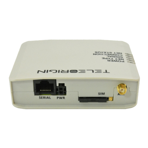
TekFast CM-1011Q User manual

TekFast 4G MODEM
User Manual
Page 1
User Manual
4G MODEM
TekFast
Model: CM-1011Q
Document History
Revision Date Remark
Rev.01-1120 CM-1011Q
All specifications are correct at the time of release.

TekFast 4G MODEM
User Manual
Page 2
TABLE OF CONTENS
1 Introduction ___________________________________________ 3
2 Specifications __________________________________________ 4
2.1 Technical Specification _______________________________ 4
2.2 Electrical Characteristic ______________________________ 6
2.3 Environmental Characteristics _________________________ 6
2.4 More Characteristic __________________________________ 6
3 Technical Hardware _____________________________________ 7
3.1 Overview __________________________________________ 7
3.2 Status Indicator _____________________________________ 8
3.3 Cable Interface _____________________________________ 9
3.4 Power Supply Interface ______________________________ 10
3.5 RJ-45 Link Interface _________________________________ 10
3.6 SIM Interface ______________________________________ 12
3.7 Antenna Interface ___________________________________ 13
3.8 Mounting Base _____________________________________ 14
4 Getting Started _________________________________________ 15
4.1 Setting up the modem ________________________________ 15
4.2 Interfacing Modem with HyperTerminal Software ___________ 16
5 Troubleshooting ________________________________________ 20
6 Safety Information ______________________________________ 21

TekFast 4G MODEM
User Manual
Page 3
1. INTRODUCTION
TekFast 4G modem is designed for reliable communication
LTE-FDD LTE-TDD UMTS/HSDPA HSPA+ GSM/GPRS/EDGE.
It provides the wireless communication link for applications
such as remote-control purposes and remote data monitoring and
acquisition. This durable and high performing modem can be deployed
in myriad Machine-to-Machine (M2M) applications including automotive
systems, fleet management, automated meter reading, smart meter,
vending and retail, security and surveillance, industrial systems,
information display, etc.
This manual provides an overview of the operation of TekFast
4G modem. It includes technical Information.

TekFast 4G MODEM
User Manual
Page 4
2. SPECIFICATIONS
General Feature
CM-1011Q is 3G/4G cellular modem for data /networking
communication over internet by remote control system.
Support Thailand version
Voltage Input 5V~24V
3GPP and Enhanced AT Commands
Signal strength and Status indicators (LED)
Control via AT commands
SIM card (1.8V/3V interface)
RS-232 with RJ45 Interface
1 SMA External antenna connecter
1 SMA External GPS connecter
Industrial grade components
Dust-proof type
GPS build‐in
Battery Backup/Power Management (Option)
Connector for Primary, Rx-diversity

TekFast 4G MODEM
User Manual
Page 5
2.1 Technical Specification
Feature Specifications
Network System LTE-FDD B1/B3/B5/B7/B8/B20
LTE-TDD B40
WCDMA B1/B2/B5/B8
GSM/EDGE B2/B3/B5/B8
Serial Interface UART 2 UART
USB 1 Port USB 2.0 with High Speed
SIM Card 1 SIM 1.8V/3.0V (U)
Serial RS-232 with RJ45 Interface
Software Work Mode Transparent Transmission
Protocol TCP/IP/IPv4/IPv6/UDP/FTP/FTPS/
HTTP/ HTTPS
AT Command Serial Port/Network
Antenna GPS Antenna 1575.42MHz±1.023MHz
SMA Connector
GSM 3G/4G 600-2700MHz 50 Ohm Gain 7 dBi
Antenna SMA Connector
V.S.W.R ≤2
Data Transfer LTE-FDD Max 10Mbps/ 5Mbps
LTE-TDD Max 8.96Mbs/3.1Mbps
DC-HSPA Max 42Mbps/5.76Mbps
WCDMA Max 384Kbps / 384Kbps
EDGE Max 296Kbps/ 236.8Kbps
GPRS Max 107Kbps/ 85.6Kbps

TekFast 4G MODEM
User Manual
Page 6
2.2 Electrical Characteristic
2.3 Environmental Characteristics
Feature Specifications
Temperature Operating -40°C ~ +85°C
Humidity Operating 5 to 95% RH
2.4 More Characteristic
Feature Specifications
Certificate EMI Standard Class B
Mounting Wall Mount
Power Supply Specifications
Operating Voltage Range DC 5 to 24 V
Battery 3.6V 300mA (Option)

TekFast 4G MODEM
User Manual
Page 7
3. TECHNICAL HARDWARE
3.1 Overview

TekFast 4G MODEM
User Manual
Page 8
3.2 Status Indicator
Status Indicator
(Green LED)
Modem Status
LED ON Permanently Modem is switched on but is not registered on the
network
LED ON and blinking slowly
Modem is switched on and registered to the network .
However, there is no active communication in
progress.
LED ON and blinking
quickly
Modem is switched on and registered to the network
with active communication in progress.
LED OFF Modem is switched off.
Signal Strength Indicator
(Red LED)
Modem Status
LED ON and 1 blinking 25% Signal Strength
LED ON and 2 blink
ing
50% Signal Strength
LED ON and 3 blink
ing
75% Signal Strength
LED ON and 4 blink
ing
100% Signal Strength

TekFast 4G MODEM
User Manual
Page 9
3.3 Cable Interface
The modem to communicates with other devices via the RJ-45 cable. The 8-pin RJ-
45 plug consists of:
1. Power input and Ground (Pin 1 and pin 4)
2. RJ-45 (RS-232) serial connection
PIN Number PIN Name Description Input / Output
1 + VCC
DC Voltage Power input
Input
2 DCD
Data Carrier Detect
Output
3 DTR
Data Terminal Ready
Input
4 GND
Ground
-
5 RXD
Receive Serial Data
Input
6 TXD
Transmit Serial Data
Output
7 RTS
Request to Send
Input
8 CTS
Clear to Send
Output

TekFast 4G MODEM
User Manual
Page 10
3.4 Power Supply Interface
The table below shows the power supply pin assignment from the modem interface
cable.
The power supply rating is :
A regulated 5V DC input voltage is recommended for operating the modem. A power
voltage exceeding 24V supplied to the modem may result in permanent damage.
3.5 RJ-45 Link Interface
The default RJ-45 link settings for the modem are:
Item Setting
Baud Rate 9600 bps
Data bits 8
Parity None
Stop bits 1
Flow Control Hardware
PIN Number Description
1 VDC Power Input
4 Ground
Power Supply Voltage
Minimum Voltage Input 5 V
Maximum Voltage Input 24V

TekFast 4G MODEM
User Manual
Page 11
To interface modem to a DTE device via standard DB 9 Pin RS-232 serial port
connector, map the interface cable pins as follow:
PIN RJ-45
RS-232
PIN DB-9
(male)
Description
RS-232
2 1
DCD
3 4
DTR
4 5
Ground
5 2
RXD
6 3
TXD
7 7
RTS
8 8
CTS

TekFast 4G MODEM
User Manual
Page 12
3.6 SIM Interface
The SIM interface is intended for 1.8 / 3V SIM cards. A SIM detect pin is added to
indicate whether or not a SIM card is inserted.

TekFast 4G MODEM
User Manual
Page 13
3.7 Antenna Interface
The 4G antenna interface uses a SMA connector.
Attach the external antenna to the
modem and tighten the connection.
4G and GPS Antenna

TekFast 4G MODEM
User Manual
Page 14
3.8 Mounting Base
Modem can be mounted onto your application by attaching it to the back of the
modem using four M3 screws

TekFast 4G MODEM
User Manual
Page 15
4. GETTING STARTED
4.1 Setting up the modem
Step 1 Prepare the SIM Card. Before using the modem, you must contact a
network operator to get a personal SIM card. Do acquire the UMTS/GPRS APN,
User-ID and Password from your network operator.
Step 2 Insert SIM card into the modem. Please refer to Chapter 3.6 “SIM
Interface” for more detailed information.
Step 3 Connect the antenna to the modem. Please refer to Chapter 3.7 ”Antenna
Interface” for more detailed information.
Step 4 Connect the modem communication interface to your device. Connect the
modem serial link interface Pin 2 to Pin 8 to your device. Please refer to Chapter 3.3
Cable Interface for more detailed information.
Step 5 Power up the modem. Connect Pin 1 and Pin 4 of the interface cable RJ-
45 plug to the input voltage and ground respectively. The status indicator LED will
light up instantly. The modem is now ready to use.
Step 6 Communicate with the modem. The modem is now ready to communicate
with your device. From your device, send AT<Enter> command to modem. If
device received an OK response from modem, the communication is successfully
established. The signal Strength LED ON and blinking.

TekFast 4G MODEM
User Manual
Page 16
4.2 Interfacing Modem with HyperTerminal Software
Configuring HyperTerminal for Modem:
Step 1 Connect the Modem to the PC COM port and run the HyperTerminal
software.
Step 2 You will be prompted to enter a description for the new connection. Enter a
name for the connection (e.g. “TEST MODEM”) and click OK to continue.

TekFast 4G MODEM
User Manual
Page 17
Step 3 In the Connect to dialog box, select the PC COM port number, which is
connected to the modem, and click OK to continue.
Step 4 In the next prompted dialog box, enter the COM port settings which is
configured in the modem and click OK to continue.
Note: Default settings for the modem are:

TekFast 4G MODEM
User Manual
Page 18
Step 5 The Connected text in HyperTerminal status bar indicates that the PC is
ready to communicate with the modem. Perform a simple check on the connection
between HyperTerminal and the modem:
The following are some other AT command examples you can use:
AT Command Description
AT+CPIN? This command is used to send the ME a password
which is necessary before it can be operated
AT+CSQ This command is used to return received signal
strength indication
AT+CREG? This command is used to check on modem
registration to the network
AT+CGMR This command is used to query for modem firmware
version number
Enter AT<Enter> command.
An OK response

TekFast 4G MODEM
User Manual
Page 19
This section suggests examples for some basic functions using HyperTerminal
sending short messages (SMS):
Step 1 Set short message format as Text mode.
AT+CMGF=1 <Enter>
Step 2 Check whether SMS center (SMSC) number is set to SIM card.
AT+CSCA? <Enter>
Step 3 Send a message to a phone number.
AT+CMGS= “Phone number” <Enter>
>Hello <Ctrl-Z>
Step 4 Wait for +CMGS for the result of sending SMS.
+CMGS: <mr>
Indicates that the SMS has been sent successfully.

TekFast 4G MODEM
User Manual
Page 20
5. TROUBLESHOOTING
5.1 The modem is not power up
Check whether the LED Status (Green) on the modem is lighted up. If it is not
lighted up, check whether the modem is supplied with the correct voltage
range between 5V to 24VDC.
5.2 The SIM Card is not ready
Check whether the LED Status (Green) on and blinking. Check whether the
SIM Card to enabled.
Can use AT+CPIN? to request for PIN status. The status Ready is SIM Card
complete.
5.3 Unable to register to the network
Check the modem status indicator. The LED should be blinking if the modem
is registered to the network.
Use AT+CREG? Command to request for the registration status. Check the
we strength of the network using AT+CSQ command. You should receive a
+CSQ response (+CSQ: {rssi}, {ber}). If the rssi value is 99, it means the
network is unknown or undetectable.
5.4 Cannot enter AT Commands or no communication between device and
modem
Check whether the modem is powered up. Check whether the SIM Lock is
turned on. Check whether the communication interface port is connected
properly. Check whether the port settings are correct. Ensure that both
modem and your device are communicating with the same settings (such as
baud rate, data bits, stop bits and parity).
5.5 Cannot connect to WCDMA/GPRS
Check whether the modem is powered up. Check whether the SIM Lock is
turned on. Check whether the modem is registered to the network. Check
whether the SIM card supports WCDMA/GPRS Service. You can verify it with
the network service provider. If the SIM card supports WCDMA/GPRS
service, check whether the APN settings are correct. Use AT+CGDCONT?
command to query or assign the APN settings. Ensure that it is correct by
confirming the APN with your network service provider.
This manual suits for next models
1
Table of contents

