TERMOTECNICA PERICOLI easyTERM Series User manual
--- IIZl:Il __
==
IIIIIIIIIIli milm~~i£~l
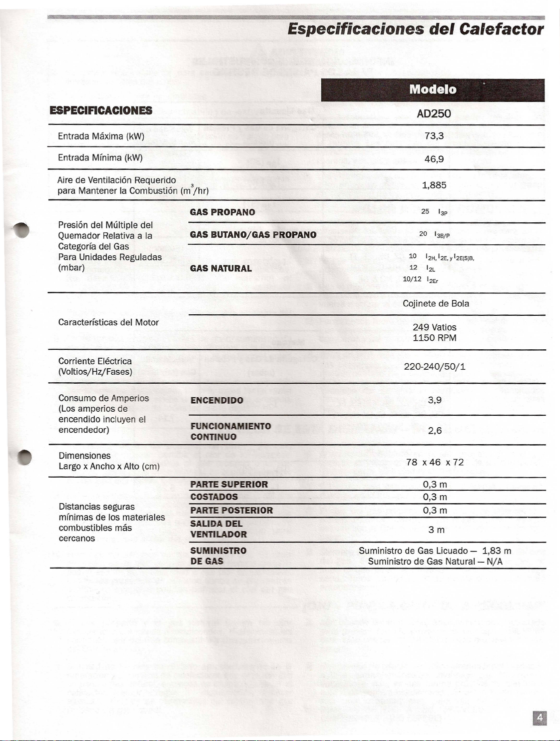
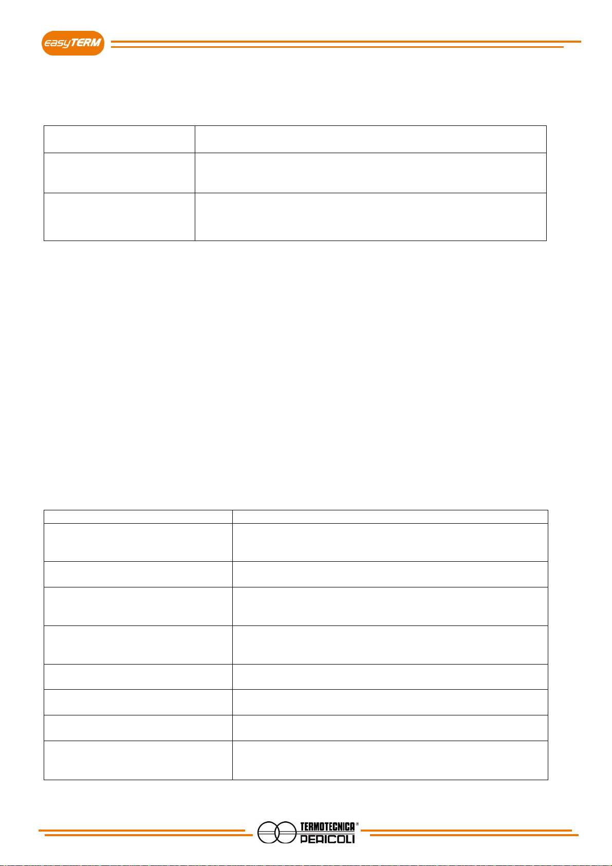
Especificaciones del alefactor
Modelo
Aire de Ventilaci6nRequerido
para Mantener la Combusti6n (m
3
jhr)
Presi6n del Multiple del
QuemadorRelativa a la
Categorfa del Gas
Para Unidades Reguladas
(mbar)
10
12H,12E•
y
12E(S)B,
12
1
2L
10 12
1
2Er
249 Vati9s
5a
RPM
Corriente Electrica
(VoltiosjHzjFases)
ConsumodeAmperios
(Los amperios de
encendido incluyen el
encendedor) F\JNCIONAMIENTO
CONTlNUO
Dimensiones
Largo x Ancho xAlto (cm)
Distancias seguras
mfnimas de los materiales
combustibles mas
cercanos
PARTE SUPERIOR
costADOS
PARTEPOSTERIOR
SAUDADEL
VENTlLADOR
SUMINlSTRO
DE GAS
a3m
a3m
a3m
Suministro de Gas Licuado - 1,83 m
Suministro deGas Natural- NjA

INFORMACION SQBRE COMBUSTIBLES
PARA LOS PAISES DE DESTINO
Gas Licuado
Paesis de Destino Categoria de Gas
y
Presion Velocidad del
(mbar) Gas (kgfhora)
HU NL
1
3P(30)
PL
1
3P(36)
BE, CH, CZ, E5,
1
3P(37) 5.25
GB, IE, PT,51 SK
BE, CH, DE, ES NL
1
3P(50)
CY,CZ, OK, EE, FI, (Butano)
1
38/P(30) 5.36
GR, HU, IT, LT,LV,
MT, NO SE (Gas Licuado)
5.25
Metano
Paesis de Destino Categoria de Gas
y
Presion Velocidad del
(mbar) Gas (m
3
jhora)
AT,CH, CZ, OK, EE, ES, FI,
1
2H(20)
GB, GR, IE, IT, LT,LV,NO, PT
7.14
SE, SI, SK TR
DE, LU PL
1
2E(20)
BE
1
2E(S)B(20)
NL
1
2L(25) 8.28

Calentadores de aire para colgar
GA
Los calentadores de aire para coplgar GA han sido diseñados para suministrar
calor a un bajo coste y en una amplia variedad de aplicaciones: invernaderos,
granjas, naves industriales...
Tecnología
Todos los modelos se basan en el principio de calentamiento de gas directo, en
el cual se usa un potente ventilador que hace que el aire pase por una cámara
de combustión en la que estáel quemador. A medida que pasa el aire por el
quemador, todo el calor que produce el proceso de combustión pasa a la
corriente de aire. Esto hace que el calentador tenga una eficacia térmica del
100%. El grado de calor del calentador se puede ajustar manualmente con
una válvula reguladora.
Diseño
Los calentadores GA funcionan con Gas Licuado de Propano (GLP), que es
un combustible muy limpio. Los productos de la combustión son principal-
mente vapor de agua y dióxido de carbono (CO2).
Para garantizar un funcionamiento prolongado en ambientes húmedos, los
calentadores GA se fabrican en acero inoxidable y todos sus componentes
eléctricos van en el interior de una caja de protección IP55.
Por razones de seguridad, los calentadores vienen equipados con una válvu-
la solenoide doble para abrir y cerrar el paso del gas. Además, los calentadores
tienen también un sensor de presión de seguridad que corta el paso del gas en
cuanto detecta una obstrucción en el paso del aire.
Todos los modelos vienen equipados también con un cable eléctrico y un
conducto de conexión del gas con regulador de presión listos para utilizar. El
calentador también estádisponible con termostato mecánico o electrónico
opcionales. Los termostatos vienen con un cable de 10 m. capaz de medir la
temperatura si asíse desea.
EQUIPAMIENTOS
GA
• Eficacia térmica del 100%
• Ajuste manual del grado de calor
• Fácil de instalar
• Fácil de manejar
• Funciona con GLP
• Válvula solenoide doble para cortar el
paso del gas
• Interruptor de seguridad para evitar el
sobrecalentamiento
• Sensor de presión para detectar blo-
queos en el paso del aire
• Protección exterior de acero inoxi-
dable y cámara de combustión
• Equipo eléctrico alojado en caja de
protección IP55
La foto muestra el equipo completo del GA55.
Sistema CELdek®– vista general
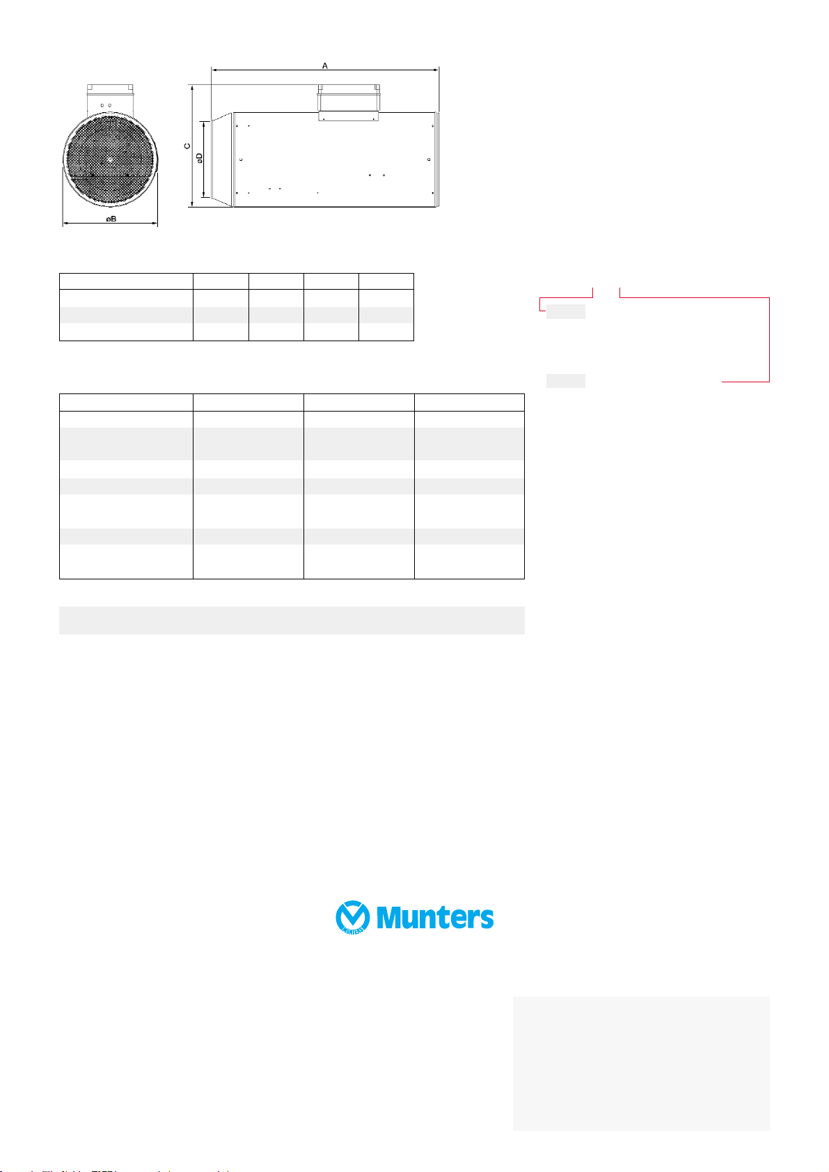
Información sobre pedidos
GA-XXX-X p. ej., GA95-c
Código para especificar medidas
55
95
95t
Código para especificar termostato
a Sin termostato
b Termostato mecánico
c Termostato digital
GA es un producto de Munters euroemme S.p.A., Italia.
Especificaciones técnicas
GA55 GA95 GA95t
Peso [kg] 25 28 32
Potencia calorífica en [kW] de 27,4 a 52 de 51,7 a 97 de 46 a 97
[kCal/h] de 23.600 a 44.800 de 44.500 a 83.400 de 39.600 a 83.400
Consumo de gas [kg/h] de 2,16 a 3,7 de 4,08 a 6,6 de 3.6 a 6,6
Presión de gas [bar] 2 2 2
Potencia [W] 200 300 600
eléctrica nominal
Voltaje [V] 230 230 230
Flujo de aire [m3/h] 1.500 3.300 6.000
[cfm] 2.550 5.610 10.140
HC/MMA/EqES-0522-07/05 2000 SOS ReklamStudio
Medidas [mm]
Tamaño del calentador A B C D
GA55 700 416 523 351
GA95 990 416 523 351
GA95t 1.140 473 608 378
Munters Europe AB, HumiCool Division, Kung Hans Väg 8, P O Box 434, SE-191 24 Sollentuna, Suecia. Teléfono +46/(0)8/626 63 00, Fax +46/(0)8/754 56 66.
Munters euroemme S.p.A., Strada Piani 2, IT-18027 Chiusavecchia, Italia. Teléfono +39/0183/52 11, Fax +39/0183/521 333.
www.munters.com
Alemania Munters Euroform GmbH, Tel +49 (0)241-89 000, Fax +49 (0)241-89 00 199, Arabia Saudí y el Oriente Medio Hawa Munters, c/o Hawa United Cooling
Syst. Co. Ltd., Tel +966 (0)1-477 15 14, Fax +966 (0)1-476 09 36, Austria a través de la oficina comercial de Alemania, Munters Euroform GmbH,
Tel +49 (0)241-89 000, Fax +49 (0)241-89 00 199, Dinamarca a través de la oficina comercial de Suecia, Munters Europe AB, Tel +46 (0)8-626 63 00,
Fax +46 (0)8-754 56 66, EspañaMunters Spain S.A., Tel +34/(0)91/640 09 02, Fax +34/(0)91/640 11 32, Finlandia Munters Oy, Tel +358 (0)9-83 86 030,
Fax +358 (0)9-83 86 0336, Francia Munters France S.A., Tel +33 (0)1-34 11 57 50, Fax +33 (0)1-34 11 57 51, Inglaterra Munters Ltd, Tel +44 (0)845-644 3980,
Fax +44 (0)845-644 3981, Italia Munters euroemme S.p.A., Tel +39 0183-52 11, Fax +39 0183-521 333, Noruega a través de la oficina comercial de Suecia, Munters
Europe AB, Tel +46 (0)8-626 63 00, Fax +46 (0)8-754 56 66, Sudáfrica y Sub-Sahara Countries Munters (Pty) Ltd, Tel +27 (0)11-971 9700, Fax +27 (0)11-971
9701, Suecia Munters Europe AB, Tel +46 (0)8-626 63 00, Fax +46 (0)8-754 56 66, Suiza a través de la oficina comercial de Alemania, Munters Euroform GmbH,
Tel +49 (0)241-89 000, Fax +49 (0)241-89 00 199, Exportación y otros países Munters Europe AB Tel +46 (0)8-626 63 00, Fax +46 (0)8-754 56 66, Region de
América Munters Corporation, Tel +1 (0)978-241 1100, Fax +1 (0)978-241 1219, Region de Asia Munters K.K., Tel +81 (0)3-5970 0021, Fax +81 (0)3-5970 3197.
Munters se reserva el derecho de efectuar modificaciones en las especificaciones, cantidades, etc., después de la publicación por razones de producción u otras.
© Munters Europe AB, 2005
Su distribuidor más próximo
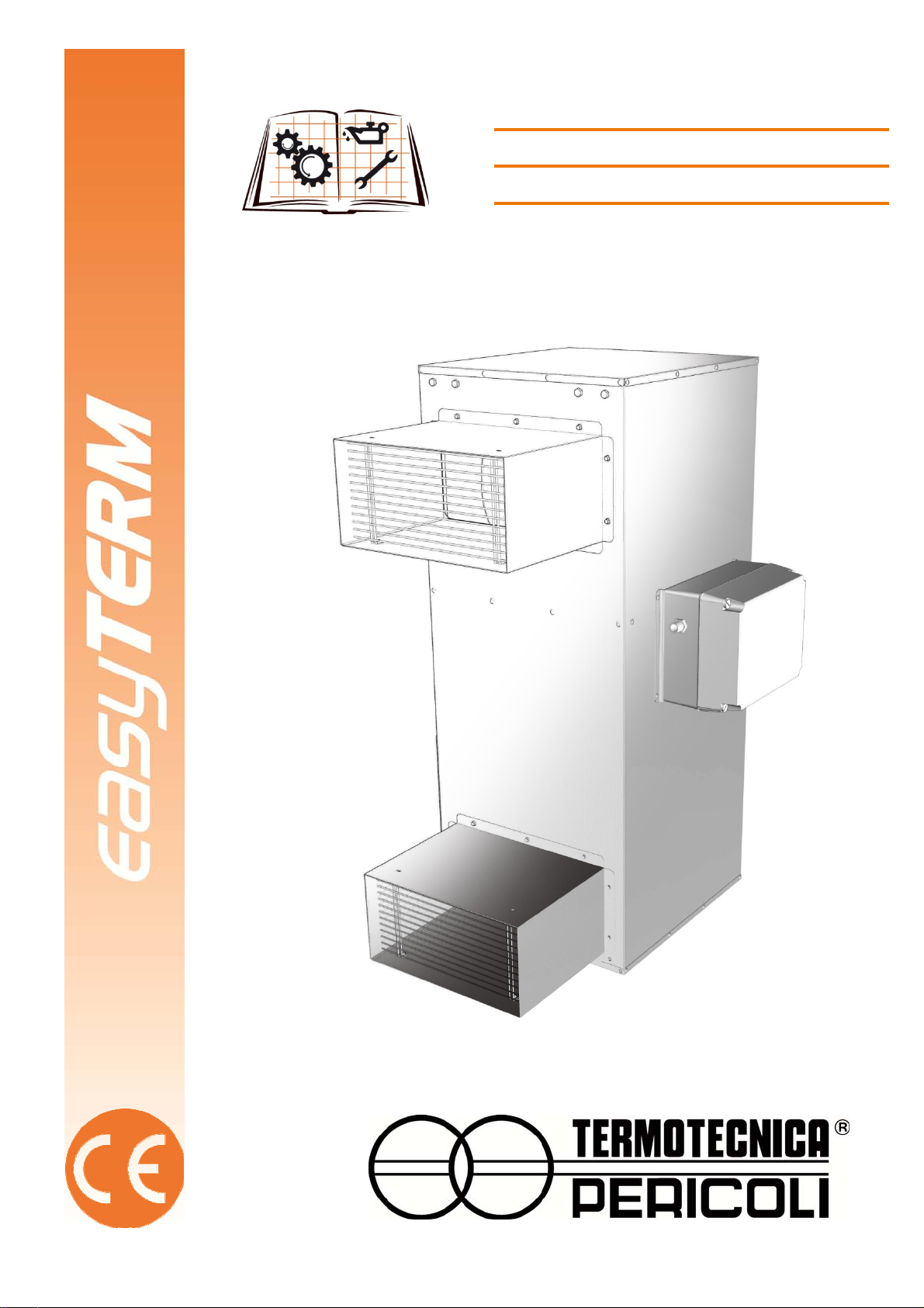
MANUALE D’USO
INSTRUCTION BOOKLET
BEDIENUNGSANLEITUNG
MANUEL INSTRUCTION

2
INDEX
INDEX ...................................................................................................................................... 2
1 - INTRODUCTION.................................................................................................................3
1.1 General warnings..........................................................................................................3
1.2 Instructions for proper disposal of the product..............................................................3
1.3 Covenants used throughout this manual.......................................................................4
1.4 Conservation of the instruction manual.........................................................................4
1.5 Recipients.....................................................................................................................5
1.6 Glossary and pictographs.............................................................................................5
1.7 Applications ..................................................................................................................9
1.8 Versions........................................................................................................................9
1.9 Identification and data label of the unit .........................................................................9
1.10 Parts description.........................................................................................................10
1.11 Transport and handling............................................................................................... 11
1.12 Warranty..............................................................Errore. Il segnalibro non è definito.
1.13 Statements...........................................................Errore. Il segnalibro non è definito.
1.14 Declaration of conformity............................................................................................12
2 - INSTALLATION................................................................................................................ 13
2.1 Before installing..........................................................................................................13
2.2 Positioning..................................................................................................................13
2.3 Electrical connection...................................................................................................15
2.4 Gas supply connection................................................................................................16
3 - OPERATION..................................................................................................................... 17
3.1 Getting started............................................................................................................17
3.2 First start.....................................................................................................................17
3.3 Start and stop .............................................................................................................17
4 - MAINTENANCE................................................................................................................ 18
4.1 Cleaning...................................................................................................................... 18
4.2 Replacement or cleaning of the nozzle.......................................................................18
4.3 Accessories ................................................................................................................18
5 - TECHNICAL SPECIFICATIONS ...................................................................................... 19
5.1 Technical data ............................................................................................................19
5.2 Spare parts.................................................................................................................19
5.3 Wiring..........................................................................................................................22
6 - PROBLEMS AND SOLUTIONS .......................................................................................23
3
1 - INTRODUCTION
1.1 General warnings
This device must be used only for the functions for which it was intended "Hot air generator”. Any other use is to
be considered improper and dangerous. TERMOTECNICA PERICOLI s.r.l. cannot be held liable for any
damages caused by improper, incorrect or unreasonable use, or if the device is used in systems that do not
comply with safety regulations.
- Check the integrity of the device at the opening of the package, paying particular attention to the presence of
damages or deformations that can lead to breakage and / or malfunction during use. In such cases do not
connect the machine to the mains. Carry out these checks before each use.
- Before connecting the unit, make sure that the data shown on the device’s plate matches that of your electricity
distribution network. The data label is located on the side of the device (par.1.9).
- Respect the safety standards set for the electrical equipment and in particular:
oFollow the installation and operation instructions concerning the use of the equipment.
oDo not place objects on the generator.
oAvoid children from using the device, and / or unable subjects without proper supervision.
oDo not touch the generator during operation or until it is completely cooled down.
oNever place water or any other liquids into the device. In the scenario of the device becoming wet,
immediately turn off the electricity by lowering the switch on the electrical panel of your system and
disconnect the power before touching the device.
oDo not insert objects inside the tank as the device may be damaged irreparably.
oDo not use accessories, spare parts and / or components that are not provided or supplied by the
manufacturer.
oAvoid touching the appliance with wet and / or humid hands.
oDo not pull the power cord nor expose it to risk of severing.
oDo not expose the unit to weather (rain, sun, etc...).
oIn case of failure or malfunction, switch off immediately and disconnect the power.
oDo not try to open or tamper the device: contact the technical service offered by
Termotecnica Pericoli Srl.
1.2 Instructions for proper disposal of the product
Under the European Directive 2002/96/EC.
At the end of its useful life the product must not be disposed of as waste.
The device can be taken to special recycling centers provided by local authorities, or at retailers that provide this
service. Disposing the product in separate parts avoids possible negative consequence to the environment and
to human health, which would both be the result of an inappropriate disposal, and allows the retrieval of
materials so that significant savings in energy and resources would be reached. As a reminder of the obligation
to dispose electrical equipment separately, the product is marked with the crossed mobile waste container.
Fig. 1.1

4
1.3 Covenants used throughout this manual
The Manual is divided into autonomous chapters, each of which is addressed to a specific operator’s figure
(installer, operator and maintainer), for which the skills needed to operate the machine safely have been defined.
The sequence of chapters follows the temporal logic life of the machine.
To facilitate the immediate comprehension of the text, throughout the manual are used terms, abbreviations and
pictograms, whose meaning is shown below.
The Instruction Manual consists of a cover, an index and a series of chapters (sections).
The home page lists the identification data of the machine and model, the revision of the manual instructions,
and finally, a picture of the machine described, drawn in order to facilitate the reader in identifying the machine
and its use.
ABBREVIATIONS
Ch. = Chapter
Par. = Paragraph
P. = Page
Fig. = Figure
Tab. = Table
UNITS OF MEASURE
The units of measure used in this manual are those provided by the International System (SI).
1.4 Conservation of the instruction manual
The instruction manual must be carefully stored and must follow and match the device in all the cases of change
of ownership incurred during the life span of the machine itself.
The conservation must be done by handling the manual with care, with clean hands and on clean surfaces. Parts
must not be removed, torn or arbitrarily modified.
The manual must be stored in a secure environment, protected from moisture and heat, and near the referring
device. The manufacturer, if requested by the User, may provide additional copies of the instruction manual of
the machine.
METHODOLOGY FOR UPDATING THE MANUAL
The Manufacturer reserves the right to modify the design or specifications of the machine as part of its policy of
improving and enabling them to comply with the statutory or other requirements or standards applicable in any
territory in which goods are sold, without notifying the Customer and without updating the manuals given to the
user. Moreover, in case of changes (previously agreed between the Customer and the manufacturer) to the
machine installed, which signifies the modification of one or more chapters of the Handbook of Instructions, the
manufacturer will be responsible for sending the modified chapters affected by the structural change (including
the new model of revision) to the User.
The User is responsible, following the directions accompanying the updated documentation, for replacing all the
copies owned, the old chapters with the new chapters, the home page, and the index with the copy updated to
the new revision level.
The manufacturer shall be responsible for the descriptions included in this manual; in case of an inconsistency
being detected in a translated version of the manual (English version), the reader must refer back to the original
Italian version of the handbook and, eventually, contact the sales department, who will make necessary
changes.
5
1.5 Recipients
The manual is addressed to: the installer, the operator, and the qualified personnel entitled to the maintenance
of the device.
EXPOSED PERSON: refers to any person exposed, wholly or partially, to a danger zone;
OPERATOR: refers to those persons responsible for installing, operating, regulating,
clearing, repairing and moving the machine, and also performing the
maintenance of the device;
QUALIFIED PERSONNEL
QUALIFIED OPERATOR:
refers to the persons who have completed courses of specialization and
training, and that have acquired experience in: installing, starting,
operating, maintaining, repairing and transporting the device, or similar
ones.
The machine is intended for industrial use (professional and not widespread) for which qualified operators are
needed, in particular, workers that:
Have reached the age of majority;
Are physically and mentally appropriate to perform works that include technical difficulties;
Have been properly educated on the use and maintenance of the machinery;
Have been considered suitable to undertake the assigned job by their employer;
Can understand and interpret the operator’s manual and the safety requirements;
Know the emergency procedures and their implementation;
Posses the ability to operate the specific type of equipment;
Are familiar with the specific applicable rules;
Have understood the operating procedures defined by the manufacturer of the machine.
1.6 Glossary and pictographs
In this section we list the non common terms included in the manual. The following also explains the
abbreviations used and the meaning of the pictograms in relation to the qualification of the operator and the state
of the machine; their use can provide quick and unique information, necessary for the proper use of the machine
under safety conditions.
GLOSSARY (Att. I p. 1.1.1 Dir. 2006/42/CE)
HAZARD A potential source of injury or damage to personal health;
DANGER ZONE All areas within and/or around the machinery in which the
presence of a person constitutes a risk to the health and safety of
himself/herself;
EXPOSED PERSON Any person that finds himself/herself entirely or partially in a
hazardous area;
OPERATOR The person responsible for installing, operating, regulating,
clearing, repairing and moving the machine, and also performing
the maintenance of the machinery;
RISK The combination of probability and severity of an injury or harm to
health that can arise in a hazardous situation;
GUARD The part of the machinery used specifically to provide protection by
means of a physical barrier;
PROTECTION DEVICE The device (other than a shelter) that reduces (alone or in
conjunction with a shelter) the risk of an operation;
INTENDED USE Use of the machinery according to the information provided in the
instruction manual;
REASONABLY FORESEEABLE
MISURE
Use of the machinery in an indifferent manner from that stated in
the instruction manual, which may result from a foreseeable
human behavior.

6
OTHER DEFINITIONS:
HUMAN-MACHINE INTERACTION: Any situation in which an operator interacts with the machine in any of
the operational phases at any time of the life of the machine itself;
OPERATOR’S QUALIFICATION: Minimum level of competence that an operator must have in order to
perform the described operation;
NUMBER OF OPERATORS: The appropriate number of operators needed to optimally perform the
described operation, it is derived from an accurate analysis made by the
manufacture, and for which the use of a different number of operators
may prevent the occurrence of the expected result or endanger the
safety of the personnel involved;
STATE OF THE MACHINE: The state of the machine includes the operating mode, for example:
running in automatic mode, maintained action control (jog), shutdown,
etc… the safety conditions on the machine such as included protectors,
excluded protectors, emergency shutdown, isolation from energy
sources, etc…
RESIDUAL RISK: Risks that remain, despite of the protective measures incorporated in the
design of the machine, the complementary protections, and the
additional protective measures.
SAFETY COMPONENT: Component:
- designed to fulfill a safety function;
- the failure and/or malfunctioning of which endangers the safety of
persons (such as a lifter; a fixed, moving or adjustable protector; an
electrical, electronic, optical, pneumatic or hydraulic device that interlock
a protector; etc…).

7
PICTOGRAPHS CONCERNING THE OPERATOR’S QUALIFICATION
Symbol Description
Generic laborer: operator lacking of specific competences, capable of performing only simple tasks
under the control of qualified technicians.
Lifting and handling vehicles driver: operator qualified for the use of vehicles used in lifting and
handling materials and machines (carefully following the manufacturer’s instructions), in accordance
with the user’s country’s laws.
Mechanic maintainer: qualified technician, able to operate the machine under normal conditions, to
run it with the maintained action control (JOG) with disabled protections, and to intervene on the
mechanical parts in order to make the necessary adjustments, maintenances and repairs. Typically
this operator is not qualified to work on electrical systems while the device is connected to the
mains.
Electrical maintainer: qualified technician, able to operate the machine under normal conditions, to
run it with the maintained action control (JOG) with disabled protections, and enabled to any kind of
operation of electrical adjustment, maintenance and repair. This operator is qualified to work on
electrical systems while the device is connected to the mains.
Manufacturer’s technician: qualified technician offered by the manufacturer to carry out complex or
particular operations or, in any other case agreed with the user. The skills are, as contingently
appropriated, mechanical and/or electrical and/or electronic and/or concerning software.
PICTOGRAPHS CONCERNING THE STATE OF THE DEVICE
The pictographs contained in a square/rectangle provide information.
Symbol State of the device
Device OFF: with electric and pneumatic power disconnected.
Machine in motion: with automatic function, movable protections closed and relative interlocking
devices activated, and fixed protections closed.
Device ON: in standby and ready to start by functional consent activation (eg. switchboard
consent), movable protections closed with relative safety device included, and fixed protections
closed.

8
PICTOGRAPHS CONCERNING SAFETY
The pictograms contained in a triangle indicate DANGER.
The pictograms contained in a circle impose PROHIBITION / OBLIGATION.
Pictograph Denomination
Hazardous voltage.
Entanglement.
Dragging.
General danger.
Do not remove safety devices.
Prohibition of cleaning, oiling, greasing, repairing or adjusting by hand when the device is in motion.
Duty to remove power before starting works or repairs.
Protective gloves required.
Safety footwear required.
Safety helmet required.
9
1.7 Applications
The easyTERM series hot air generators run on GPL (Liquid petroleum gas) and methane as the combustion
fuel. The easyTERM generators are of direct combustion type. The air is heated by means of the thermal energy
generated during combustion and is transferred to the environment to be heated with the combustion products,
thereby rendering the thermal energy produced 100% available. The environment must be suitably ventilated in
order to ensure sufficient air exchange.
Do not use the generator in basements or below ground level or in premises destined for domestic use.
There are a series of safety devices which come into effect in the event of faulty function. The electronic control
device intervenes in the event of irregular flame or flame which tends to go out, stopping the burner and igniting
the burner block button indicator.
EasyTERM stops if there is a fault in ventilation.
The materials used in building the machine ensure reliability and durability in time.
This device must be used only for the functions for which it was intended
- Hot air generator.
Any other use is to be considered improper and dangerous.
1.8 Versions
Hot air generators easyTERM are available in the following versions:
BE7.2C06020100000001 Hot air generator easyTERM 80 74kW 4.000m³/h 230V 50Hz 1~+N
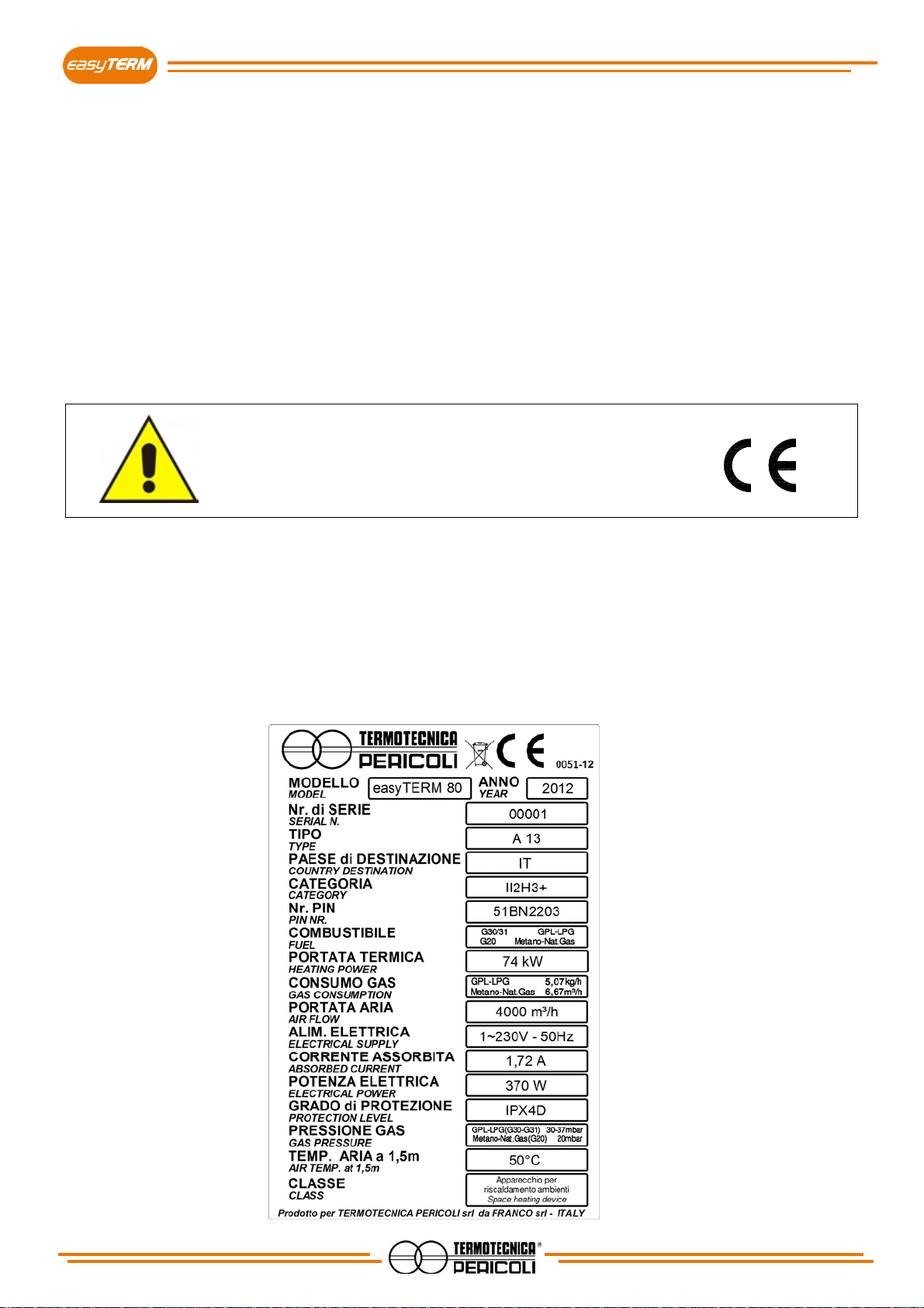
1.9 Identification and data label of the unit
Each machine is identified by the CE plate on which, indelibly set, is reference data of the device itself.
In any communication, either with the manufacturer or with the customer service, always cite these references.
Fig.1.2
10
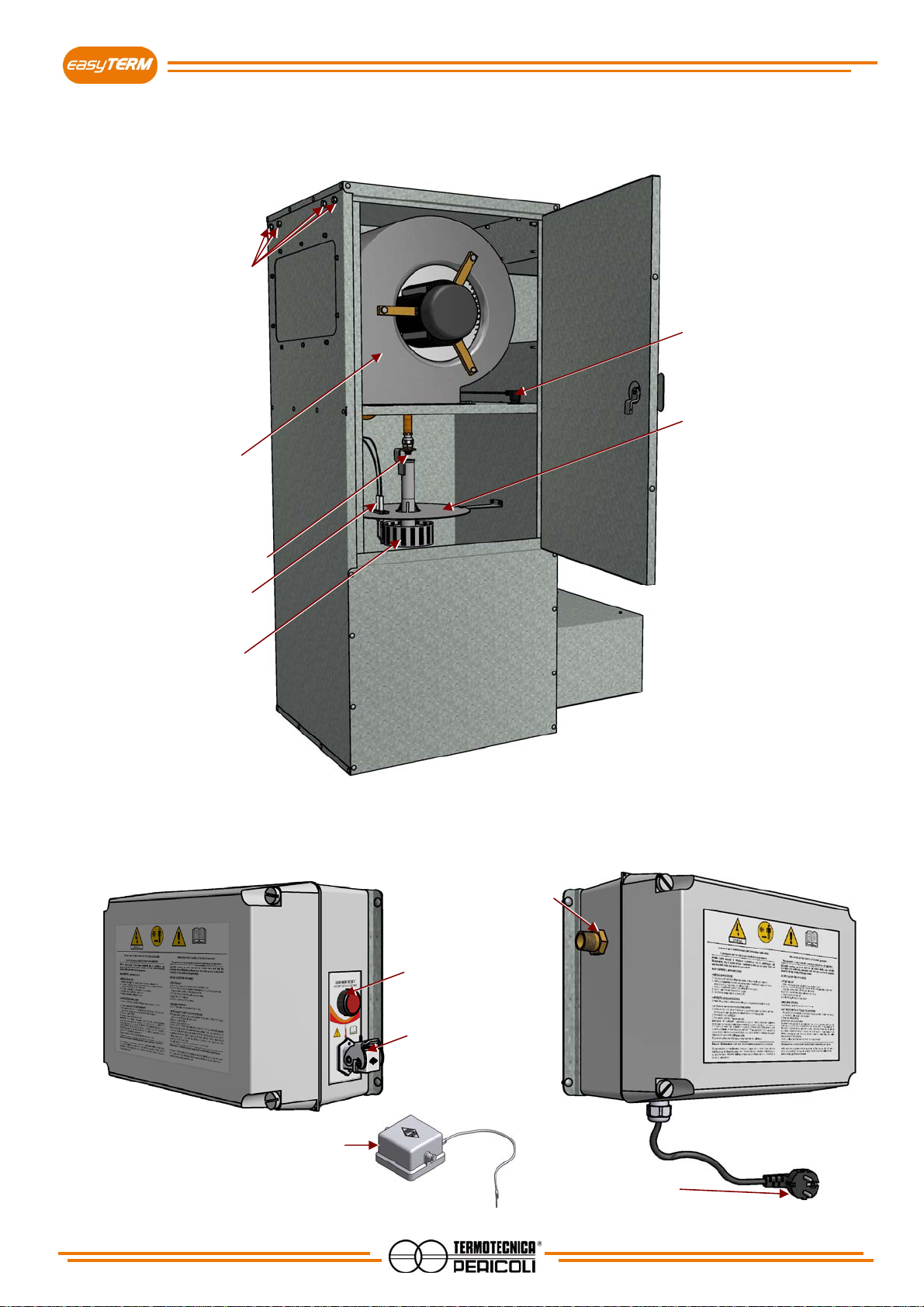
1.10 Parts description
Constituent parts of the hot air generator.
Electrical connections box
(The gas valve and all the components for the flame control and ignition are contained inside)
Fig.1.3
Burner disk
Burne
r
Ventilato
r
Thermostat
Elettrodes
flame sensing / ignition
Gas nozzle
n.8 M8 insert nut fo
r
fixing / suspension
(n.4 on the opposite side)
Reset button
Thermostat
socket
Gas suppl
y
connection
GAS ½” M
Electrical supply plug
Schuko CEE 7/4
Connector - bypass
(insert for “manual mode” - par.2.3)

11
1.11 Transport and handling
The machine has been properly packaged before being put into strong carton boxes.
Prevent damages to the components of the device by taking care when opening the package.
Verify the integrity of the machine by controlling that there are no visible damaged parts.
Do not dispose the packaging elements in the environment; they must be placed in proper collection
points.
EasyTERM generator can be lifted and hung by using the proper brackets.
WARNING!
Before handling the device:
a. stop the machine,
b. disconnect the electricity supply,
c. interrupt the water supply.
d. Wait for the exchanger to cool down
To lift the machine, use a suitable lifting device (consult the weights table).
Lift the machine slowly, being careful not to drop it and move the straps depending on the centre of mass.
SALES TO BUSINESSES HAVING THEIR SEAT OUTSIDE ITALY
TERMOTECNICA PERICOLI S.r.l. undertakes to remedy any non-conformity (defect) of the products for which
he is liable, occurring within 12 Months from invoicing date of the products to the purchaser, provided he has
been notified timely about such defect in compliance with the terms and conditions hereinafter set out.
In addition, the present warranty is conditional on both the following conditions:
A) the compliance with the instructions guide supplied by TERMOTECNICA PERICOLI S.r.l. and
B) payment in full at due date of the sale price agreed for the products.
In such case TERMOTECNICA PERICOLI S.r.l. will, at his choice, either replace or repair the products (or parts
of the products) which result to be defective. This warranty (i.e. the obligation to replace or repair the products)
replaces any other legal guarantee or liability provided by law. It is consequently agreed that, except in case of
fraud or gross negligence of TERMOTECNICA PERICOLI S.r.l., any other TERMOTECNICA PERICOLI S.r.l. ‘s
liability (both contractual or extra-contractual) which may arise from the products supplied and/or their resale
(e.g. compensation of damages, loss of profit, etc.) is expressly excluded.
Any complaints concerning the conditions of packing, quantity or outward features of the products (apparent
defects) must be notified to the Supplier in writing within 8 days from receipt of the products; failing such
notification the purchaser’s right to claim the above defects will be forfeited. Any complaints relating to defects
which cannot be discovered on the basis of a careful inspection upon receipt (hidden defects) must be notified to
TERMOTECNICA PERICOLI S.r.l. in writing within 8 days from discovery of the defect; failing such notification
the Purchaser’s right to claim the above defects will be forfeited. The notice must indicate precisely the defect
and the products to which it refers. TERMOTECNICA PERICOLI S.r.l. does not accept return of products
lacking its express written authorization. Where TERMOTECNICA PERICOLI S.r.l. accepts such return of the
products the purchaser shall deliver the products to TERMOTECNICA PERICOLI S.r.l. at purchaser’s risks and
costs.
Notwithstanding the above the present warranty does not cover the normal wear and tear of the products and
the defects deriving from modifications made by the purchaser without TERMOTECNICA PERICOLI S.r.l.’s
consent.
With respect to possible consumer claims involving the application of domestic rules implementing the European
directive 1999/44/CE of 25 May 1999 on certain aspects of the sale of consumer goods and associated
guarantees, the purchaser accepts to bear the exclusive responsibility for any obligation arising within such
context. Consequently the parties expressly agree to exclude any right of redress by the purchaser against
TERMOTECNICA PERICOLI S.r.l. based on the above Directive and the purchaser undertakes to hold
TERMOTECNICA PERICOLI S.r.l. harmless against any such action of redress made by subsequent sellers of
the distribution chain.
1.13 Statements
The machine is built in accordance with the EC directives that are relevant and applicable at the time of the
market entry of the machine itself.
The machine is not among those mentioned in the Att. IV of the Directive 2006/42/CE.

12
1.14 Declaration of conformity (All. IIa DIR. 2006/42/CE)
TERMOTECNICA PERICOLI S.r.l.
Company
Reg. Rapalline 44 - P.O. BOX 262 17031 SV
Address Postal code Province
Campochiesa d’Albenga Italia
City Country
DECLARE THAT THE MACHINE
Hot air generators easyTERM 80
Description Model
BE7.2C06020100000001 2012
Series/Registration number Year of construction
easyTERM - hot air generator
Commercial denomination
Heating device
Intended use
Meets the following essential requirements:
DIRETTIVA MACCHINE 2006/42/CEE
DIRETTIVA GAS 2009/142/CEE (ex 90/396/CEE)
DIRETTIVA BASSA TENSIONE 2006/95/CEE
CERTIFICATO DI ESAME CE 51BN2203/ED
Complies with the EU directives
EN 437:2003 + A1:2009
EN 1596:1998
EN 1596:1998/A1:2004
AND AUTHORIZES
PERICOLI ROBERTO
Nominative
Reg. Rapalline 44 - P.O. BOX 262 17031 SV
Address Postal code Province
Campochiesa d’Albenga Italia
City Country
TO COMPILE THE TECHNICAL FILE ON HIS BEHALF
Place and date of the document
Albenga, 15th October 2012
Function Administrator
D.C.: DC N-008/000001

13
2 - INSTALLATION
2.1 Before installing
In order to start the hot air generator easyTERM, the following conditions are required:
• connection to the electric power supply with voltage and frequency suitable for the machine and with grounding
and safety devices;
• the machine is preset and is sold to work with natural gas (methane). In case of use with LPG, you must
refer to cap. 4.2 for instructions. Connection to the suitable gas supply (see technical details);
The installation must meet the safety requirements
provided by local regulation in force.
Make sure that all the connections necessary to operate the equipment have been properly prepared.
2.2 Positioning
The hot air generator easyTERM must be installed vertically, as shown in fig. 2.2.
Assemble the inlet and outlet ducts (with supplied screws), as shown in fig. 2.1.
Use the supplied special supports to hang or to anchor the appliance. Use an adequate
anchoring system to keep the machine in the working position.
Positioning of the easyTERM must be done according to the minimum recommended distances that allow a
proper machine operation and to perform maintenance when needed.
Choose, depending on the type of installation, the most suitable position within the room.
In case of long periods of unuse,
close the air inlet and the air outlet with insulating material!
fig. 2.1 - Inlet and outlet duct assembling
n.20 screws
flanged hexagonal
head 4,2x13
self-tapping
bracket
washe
r
grower
washe
r
M8 scre
w
bracket
washe
r
grower
washe
r
M8 scre
w

14
Installation of the machine must be done complying the safety distances
(law DIN EN 13857 – 4, 4.1, 4.2)
INSTALLATION EXAMPLE IN A ZOOTECHNICAL BUILDING
AIR INLET
AIR OUTLET
The installation height must be compatible
with the farm typology
OUTSIDE INSIDE
OUTSIDE INSIDE
OUTSIDE INSIDE
OUTSIDE INSIDE
Protect the machine
against
severe weather

15
2.3 Electrical connection
The installation involves the use of a humidistat or a thermostat ON/OFF controlling the power
of the machine; it is still possible to use, alternatively, a switch ON/OFF, in this case the start
and stop of the machine must be done manually.
The choice, however, does not affect the installation procedure described below.
Electrical connections must be undertaken by specialized, experienced and trained
technicians, in accordance with the current legislation.
Ensure that the electricity supply specifications correspond to those indicated in the
in this manual.
It is obligatory that the device is grounded using an efficient ground line.
The installation must foresee a device enabled to disconnect the machine from the electric supply.
16
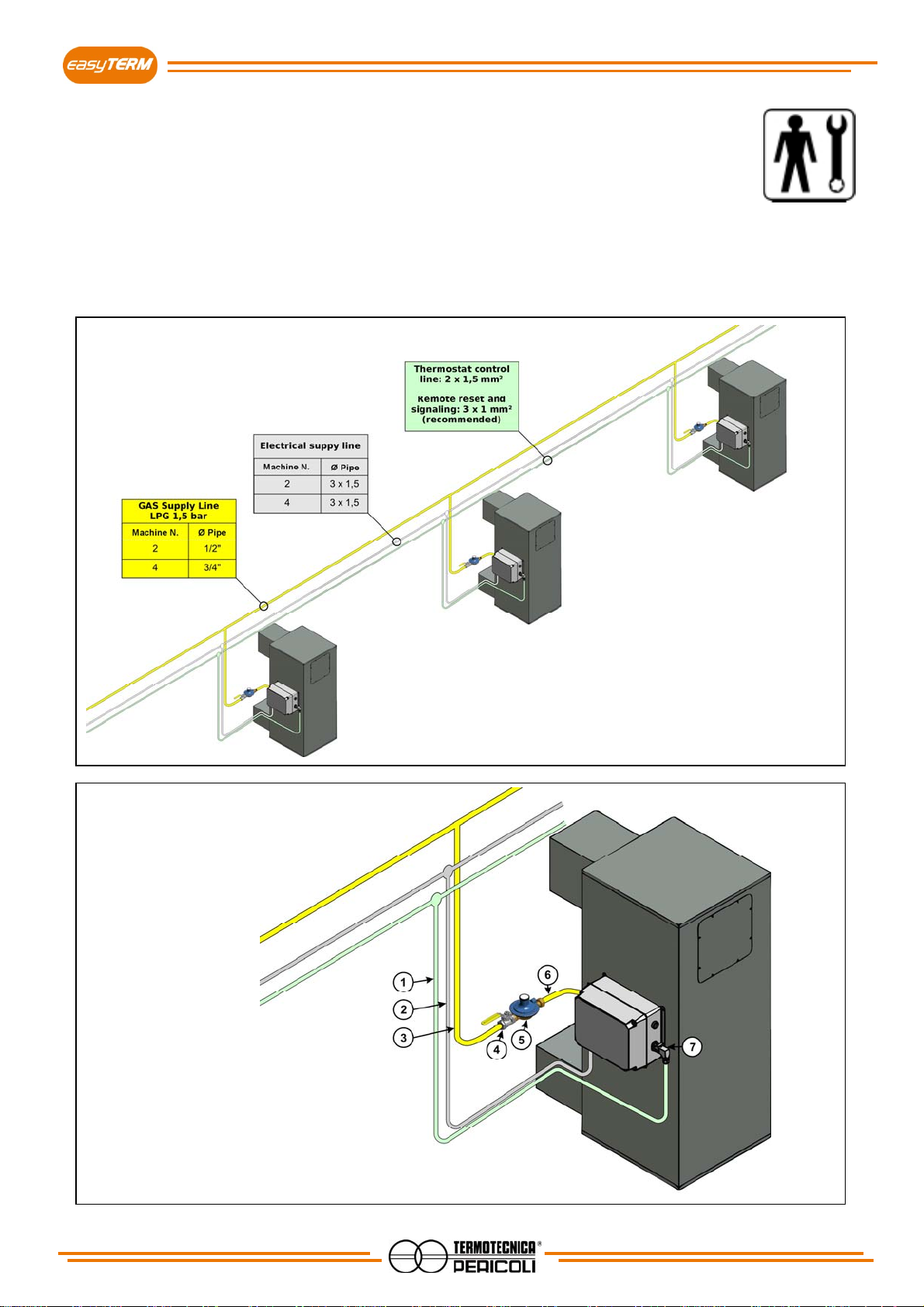
2.4 Gas supply connection
The easyTERM generator comes complete with gas valve inside the machine’s electrical box.
The plug for the line connection is 1/2”.
The gas supply line’s pressure must be in compliance with the data indicated in the
following table;
Connect the supply tube to the pressure reducer, and the latter to the cylinder of LPG or
the CNG line;
Use a flexible tube with a maximum length of 2m and make sure that there are no
bottlenecks;
The system must be adapted to the characteristics of the equipment in use and comply
with the current regulations.
1 - Thermostat control line 2x1,5
2 - Electrical supply 3x1,5
3 - Gas supply (line to valve) 1/2"
4 - Interception valve 1/2"
5 - Gas pressure regulator 30mbar
6 - Gas flexi hose 1/2"
7 - Thermostat socket
This manual suits for next models
1
Table of contents
Popular Heater manuals by other brands

Heinner
Heinner HFH-L2000SL instruction manual

MILL
MILL Invisible & Glass Series Assembly and instruction manual

Charnwood
Charnwood SLX20 Operating and installation instructions

Magnum
Magnum Ruutu L 6.0kW operating instructions

Clarke
Clarke DEVIL 371PC Operating & maintenance instructions

CLIMASTAR
CLIMASTAR SMART TOUCH 500 Installation manual and user's guide


