Terra STI520 User manual

DVB to IP streamer STI520 EN
Vers. 1.01
1. Product description
This is a dual tuner local TV (DVB-T/T2/C) to IP gateway for home users. The device allows multiple users to
watch local TV on their smartphone, tablet, smart TV or personal computer. The device also allows video
recording to the USB or local network drive for watching the records later. It is possible to access the device from
outside your local network (e.g. using the smartphone and mobile data connection) and watch TV and records
remotely.
“TerraTV” Android app is designed specifically for this product for video playback. Third-party video players
are supported as well.
STI520P is packed with an external power supply.
The device is intended for indoor usage only.
2. Safety instructions
The streamer is powered from the external power supply +12 V. This voltage is not dangerous to life.
Any repairs must be done by the skilled personnel.
Do not plug the power supply of the streamer into the mains until all the cables have been connected
correctly.
Streamer shall not be exposed to dripping or splashing water.
Avoid placing the streamer next to central heating components, near highly combustible materials and in
areas of high humidity.
If the streamer has been kept in cold conditions for a long time, keep it in a warm room no less than 2 hours
before use.
Do not place the streamer on unstable surfaces, where the unit may fall and resulting possible damage.
Do not insert any objects into the ventilation openings.
The ventilation should not be impeded by covering the streamer with items, such as newspapers, cloths,
curtains.
Scan for downloading TerraTV app
from Google Play
This product complies with the relevant clauses of the European Directive 2002/96/EC. The unit must
be recycled or discarded according to applicable local and national regulations.
Equipment intended for indoor usage only.
This product is in accordance to following norms of EU: EMC norm EN50083-2, safety norm
EN62368-1 and RoHS norm EN50581.
This product is in accordance with Custom Union Technical Regulations: “Electromagnetic
compatibility of technical equipment“ CU TR 020/2011, “On safety of low-voltage equipment“ CU TR
004/2011
This product is in accordance with safety standard AS/NZS 60065 and EMC standards of Australia.
2
3. External view
Rear view
Front view
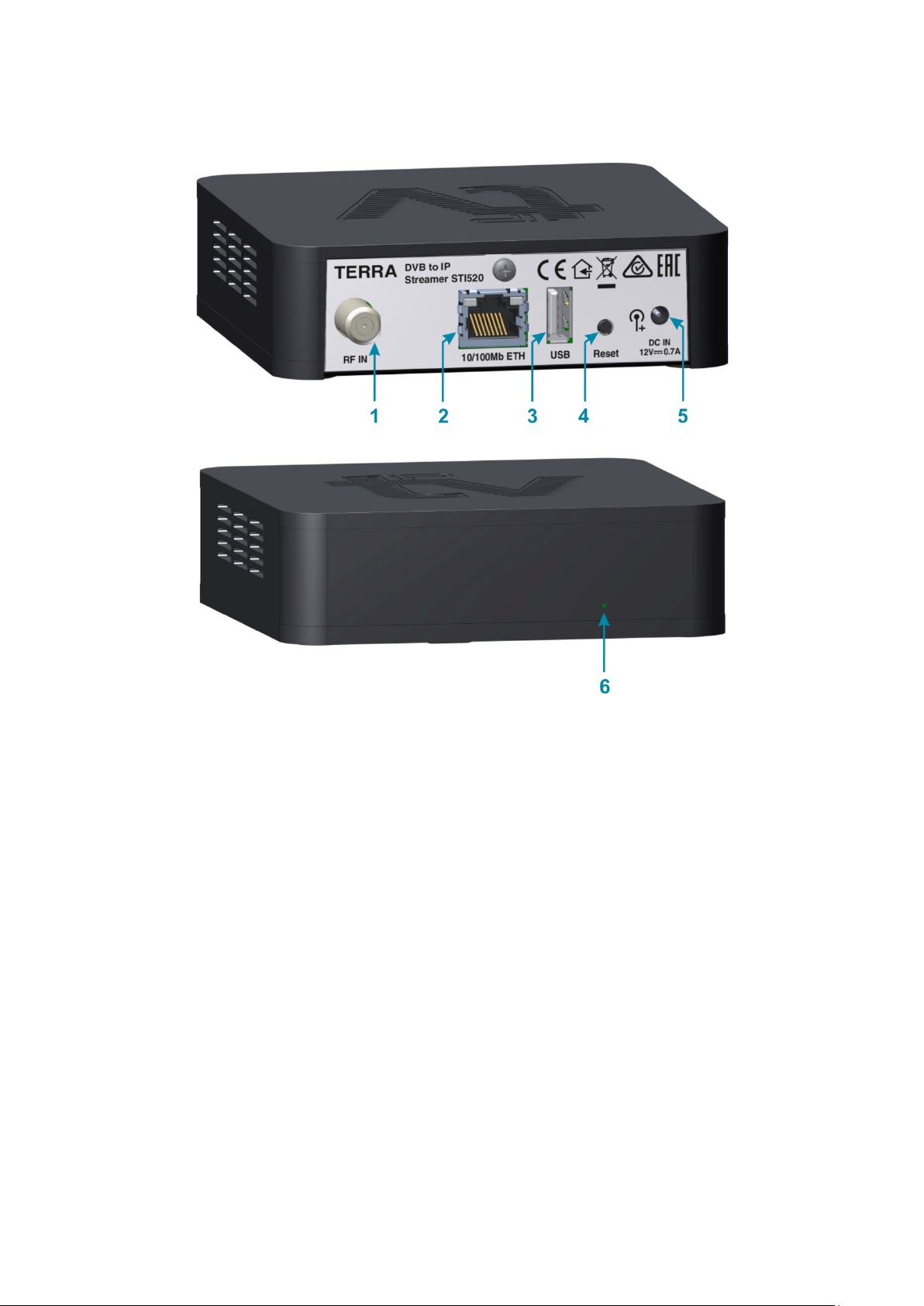
Figure 1. External view of the streamer.
1– RF IN – RF signal (antenna) input connector. F type;
2– 10/100Mb ETH – IPTV and WEB control interface. RJ45 socket;
3– USB – USB connector for video records storage. USB-A socket;
4– Reset – device reset and restore defaults button (see description at section 6);
5– DC IN – DC powering entry for 3.5/1.3 mm DC jack;
6– device status indication light;
4. Installation instructions
Read the safety instructions first.
Connect antenna or cable signal source to the RF input [1].
Plug Ethernet cable [2] and connect to the home router or personal computer.
Connect device power supply to the device DC-IN connection [5] and plug the power supply to the mains.
4.1 WEB browser requirements
Streamer supports the following WEB browsers:
• Chrome starting from version 66
• Opera starting from version 53
• Safari starting from version 12.1
• Firefox starting from version 53
• Edge starting from version 80
Internet Explorer is not supported.
4.2 Requirements for video records storage
• SSD or USB memory stick is recommended. HDD usage is not recommended;
• If the USB drive consumes more than 2.5 W (500 mA) of power, it must be powered through an external power
source;
• USB Memory stick must be capable of writing to at least 120 Mbit/s;
• While writing DO NOT detach the drive from the device. This can corrupt files or the drive itself;
3
• Use “unmount” (see section 5.5.1) function before removing the drive;
• It is recommended to use the disk with NTFS or exFAT file system. In case of FAT32, the file size will be limited
to 4 GB, and some of TV programs may not fit in the file.
• A USB hub can be used to connect multiple USB devices. However, only one disk partition will be active for
recordings storage.
4.3 Initial configuration
To access the streamer WEB configuration interface, wait until the green or red status indication light appears
on the device front panel.
4.3.1 Accessing the device when connected to the home router
The DHCP client is enabled on the device by default. This means that the IP address will be assigned to the
device automatically by the network router. The device also has the mDNS protocol enabled so you can access
the device by entering this URL in your WEB browser address bar:
http://iptv.local
The login window should appear after a short period of time.
If you cannot access the login window please read “troubleshooting instruction manual” for possible
connection problems solving.
NOTE: mDNS is supported on Windows and MAC operating systems only. If you are using other OS, connect
the device directly to the personal computer as described in the section 4.3.2.
4.3.2 Accessing the device when connected directly to the personal computer
When device is connected directly to the personal computer or if there is no DHCP server in the network, the
default IP address of streamer is:
192.168.1.10
Ensure that subnet 192.168.1.0 is accessible from your computer. If you are not sure, please read
“troubleshooting instruction manual” for more information. Enter this IP address in your WEB browser address
bar and the login windows should appear in a short period of time.
4.3.3 Login access window
Enter the following default login access parameters after login window shows up:
Username: admin
Password: admin
4.3.4 Initial country selection
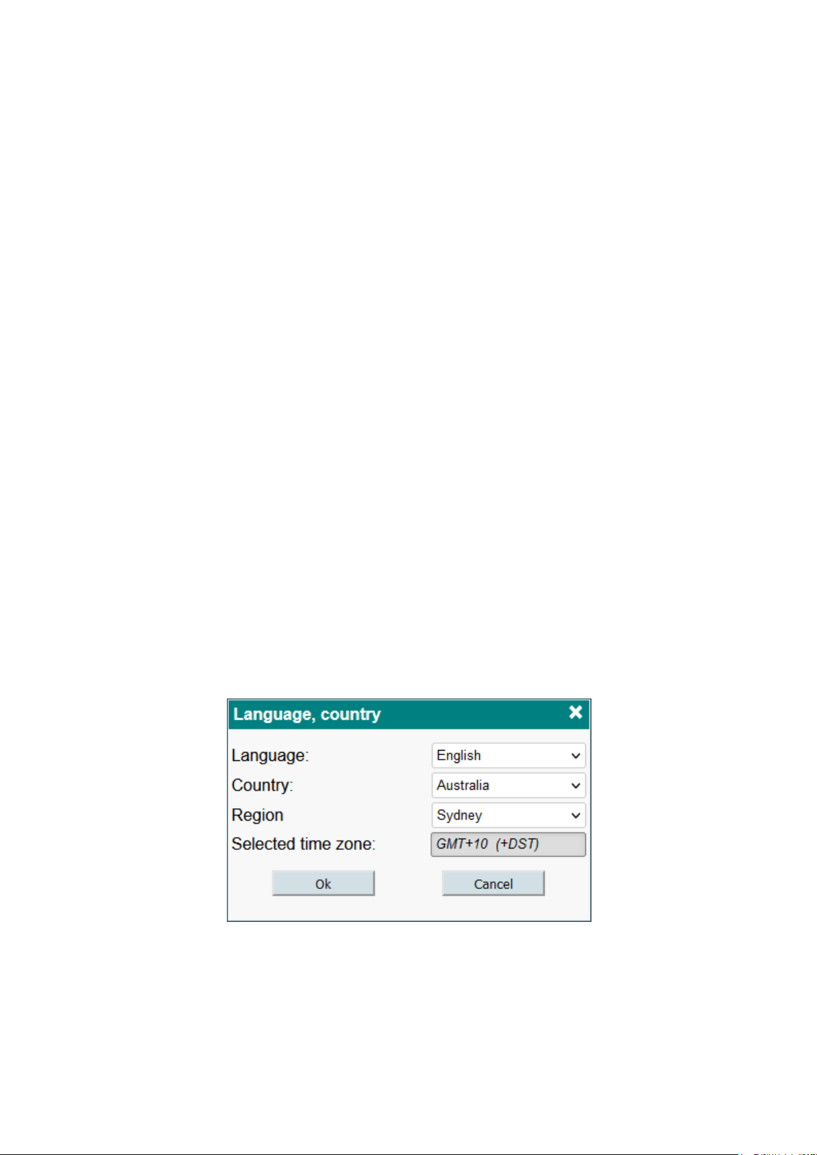
When you connect to the device for the first time, you will be prompted to select the language, country, and
region where the device is located (see Figure 2). Incorrect country selection can affect TV channels grid, time
zone and other important device settings. Make sure the setting is set correctly.
Figure 2. Language, country, region selection.
Language selection affects the language of the control interface. Different browsers may have different
languages used simultaneously. The language setting is saved in the WEB browser as a cookie.
5. Menu description
On the top of every WEB configuration window there are 3 main icons. See detailed icons description below:

4
System diagnostics information. Exclamation mark and red circle indicates that there is a
problem with device and user attention is required. Click on this icon to see the detailed
diagnostics errors description window.
Download and read the latest device user manual by clicking on this icon.
Currently logged-in user name is shown at the top right WEB configuration window side. You can
log-out anytime from the WEB configuration window by pressing on the log-out icon.
Device name. This name can be changed if you click on the current device title text.
5.1 Home
This is the default page of the device when the user logs into the control panel.
Figure 3. Connection diagram.
Figure 3 shows all possible connections and their states. If there is a problem with the connection, the line is
shown in red color and the notification text describing the problem is displayed in the diagnostics information
window. Depending on the device setup, some connections may not be displayed. For example, if no storage
location is specified, neither the USB nor the network drive will be displayed.
The list on the right side shows the video stream viewers list that are currently watching or recording video. If
SRT protocol is used, mark is displayed in the corner. If video content is being recorded, a mark
will be displayed.
5.2 RF inputs
Before watching TV programs, you must scan all RF channels or insert RF channels frequencies manually.
5.2.1 Antenna settings
The RF input [1] connector can supply the power to the preamplifier. The power can be turned on/off as
shown in Figure 4. See device technical specification for voltage value and current limitations.
Figure 4. Preamplifier power.

5
5.2.2 Channel scanning
The “Autoscan” table checkboxes show all supported modulation standards (see Figure 5). DVB-T and DVB-
T2 scanning use a country-specific frequency grid. Make sure that your country is selected correctly. Select
which standards the “autoscan” function should use and click “Scan” button. The device will automatically scan all
available radio frequency (RF) channels.
Figure 5. Supported DVB standards of channels autoscan function.
After the procedure is completed, all found RF channels will be displayed in the “List of RF channels” table as
shown in Figure 6.
Figure 6. List of RF channels.
“TV channels” column shows TV programs which were found during the scanning operation at specified
frequency. All TV programs and radio stations are grouped by video quality or program type (HD, SD or radio).
You can hover on the group to see the TV programs and radio stations names.
“Status” column shows the RF signal quality bars icon. You can also hover on the status bars icon to see
detailed signal parameters such as signal to noise ratio (SNR) and RF channel level values. Device continuously
monitors each RF channel’s signal parameters.
Depending on the modulation standard, you can also see signal parameters such as bandwidth, symbol rate,
frequency, channel number, PLP number.
The following table buttons have additional functions.
Re-scan RF channel for TV programs.
Remove RF channel from the list.
Fill required RF channel fields add new RF channel manually.
When adding the RF channels manually you must fill the following fields depending on the selected
modulation standard.
DVB-T Bandwidth, frequency.
DVB-T2 Bandwidth, frequency, PLP number.
DVB-C Symbol rate, frequency.
Then press the icon on the bottom right side of the table and new added RF channel should appear in the list.
5.3 TV channels
The full list of available TV programs is displayed in this table (see Figure 7).
6
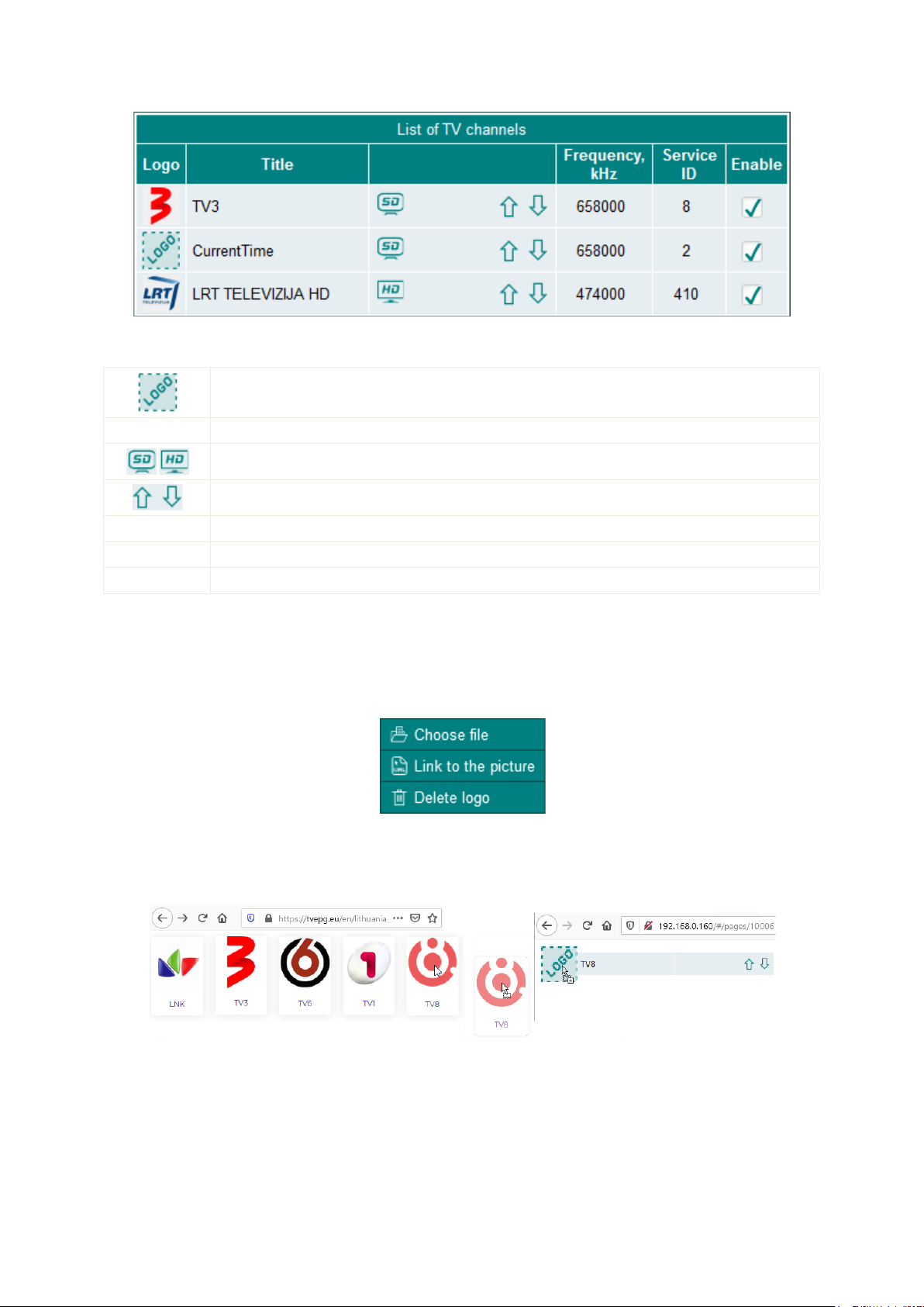
Figure 7. List of TV programs.
Below is a detailed description of table columns.
User assigned channel logo. See section 5.3.1 for detailed explanation for adding/removing
channel logo picture.
Title TV program title.
TV program type.
Adjust the position of TV program in the playlist file.
Frequency RF channel frequency which TV program belongs to.
Service ID TV program service ID.
Enable Checkbox will include or exclude the TV program in the playlist file.
5.3.1 Add channel logo
There are two available options which allow you to assign the logo to the selected channel.
1. Click the left mouse button on the channel logo. The pop-up menu shown in Figure 8 will appear. You may
then choose the file from your computer (GIF, PNG, JPG formats are supported) or may enter a WEB link where
the picture exists. HTTP or HTTPS protocols are supported for downloading the picture from WEB links. Make
sure the device can connect to the Internet.
Figure 8. Channel logo assigning pop-up.
2. Open a page with logo images in one browser window. In the next browser window, open the device “TV
channels” settings window. Then drag the image from one window to another window and drop to the logo
position as shown in Figure 9.
Figure 9. Drag and drop the logo.
Right click and select “Delete logo” if you want to remove the logo image from the STB channels list and
device.
5.4 Playlist
The device supports M3U playlist and XMLTV Electronic Program Guide (EPG) formats for third-party video
players. You can import the playlist and EPG files to your favorite video player to watch a video stream.
7
5.4.1 Playlist parameters
Figure 10. Playlist parameters.
“Playlist name” – playlist name that will be inserted into the playlist file.
“URL key” – secret password for playlist file security. Other users who don’t know correct URL key will not be
able to use the playlist file and watch video. After filling the URL key with a secret key phrase you must download
the playlist file again and import downloaded file to the video player that you are using. Leave this field blank if
playlist security feature is not required.
“Include scrambled TV channels” – enabling this checkbox will include scrambled TV channels in the playlist.
“Allow channel grouping” – will allow you to assign TV channels into user defined groups. M3U playlist format
supports linear groups only, while DLNA supports up to three levels grouping. M3U playlist entries grouping must
be supported by the video player that you are using. Otherwise this function will not work.
“Edit channel groups” – add or modify existing channels groups. Click on the icon to edit. See section 5.4.2
for more information.
Click on the “Update” button to changes take effect.
5.4.2 Edit channels groups
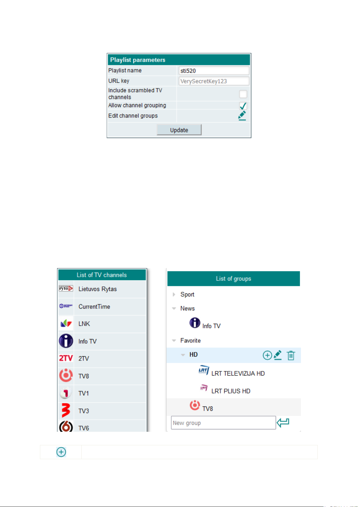
TV channels can be grouped in the playlist. The left table shows all active TV channels. The right table shows
the groups tree. See the example in the Figure 11. Enter a name for the group in the “New group” field and press
enter to create it. To create a subgroup in the existing group, select the main group’s title as shown in the Figure
11 for group “HD”. Three buttons will appear.
Figure 11. Channels groups.
Create a new subgroup.

8
Rename existing group.
Delete group and all its content.
To assign a channel to the group, drag a TV channel from the left table to the right table group name. The
channel will be assigned to this group. The same channel can belong to several groups. M3U and DLNA playlists
will be updated after any change automatically.
5.4.3 Playlist file
Figure 12. Playlist available from local network.
Figure 12 shows the playlist and EPG URL for third-party players. This playlist file and EPG information are
accessible from the local network only. Click on the icon to copy the URL and then open a video player and
paste this URL.
Figure 13. Playlist available from remote network.
If the device is accessible from the remote network you will see a playlist link with an external IP address in
the next configuration interface table as shown in Figure 13. Make sure your router is set up properly to access
the playlist and video stream. If your router supports UPnP, remote access can be managed as described in the
section 5.6.2.
NOTE: if you make changes in the playlist configuration window, you also must download the updated playlist
file and import into the video player that you are using.
5.5 Recordings
Before using device video recording feature you must configure the storage where video records will be
stored. Then create a recording schedule.
5.5.1 Storage
Storage settings let you choose the type of storage between the USB and network drive. “Status” shows
mounting status of the drive. If the disk is mounted, the free disk space that will be used for recordings will be
displayed. If the USB option is selected, a list of available USB partitions will be displayed. See Figure 14.

9
Figure 14. Storage configuration.
If the storage type is a network drive, the “Network drive address” field must specify the full path to the drive.
Domain name is not supported in this field. The address must begin with // characters, followed by the IP
address. If the drive requires username and password add them to the appropriate fields. Otherwise, leave these
fields blank. Make sure the connection to the network drive is stable throughout the connection. Otherwise, the
recording process of the unit may deteriorate.
The “Keep records for” option specifies how long the records will be stored. They will be deleted automatically
after the specified time.
The device will create “records” folder in the storage and all records will be stored there. Switching the drives
between devices will automatically detect previously recorded TV programs.
5.5.2 Recording schedule
The schedule has two different options – one-time and weekly recording. Figure 15 shows both cases.
Figure 15. Recording schedule.
“One time recording” - means a single recording at the exact time and specified duration. The start time can
be selected up to 6 days in advance. Such schedule entry is shown in Figure 15 - “Polsat” record. If “One time
recording” checkbox is selected, the checkboxes indicating the days of the week will be ignored.
“Weekly recording” means that the TV channel will be recorded on each selected day of the week at the
selected start time. Such schedule entry is shown in the Figure 15 - “BBC World News” record.
To delete a scheduled record entry, just click the icon and confirm. If a video is being recorded at that
time, the current recording will end and be saved to a file.
5.5.3 Recorded TV programs
This section displays a list of recorded files. After the video has been recorded, it will be automatically added
to this list. M3U, DLNA playlist files in the streamer will be updated automatically.
Figure 16. Recorded TV programs.
Figure 16 shows two recorded video in the recorded video files list. Clicking the icon will download the
recorded file to the computer. Clicking the icon will erase the record from the storage.
5.6 IP parameters
Three submenu sections allow changing network related settings.
10
5.6.1 LAN
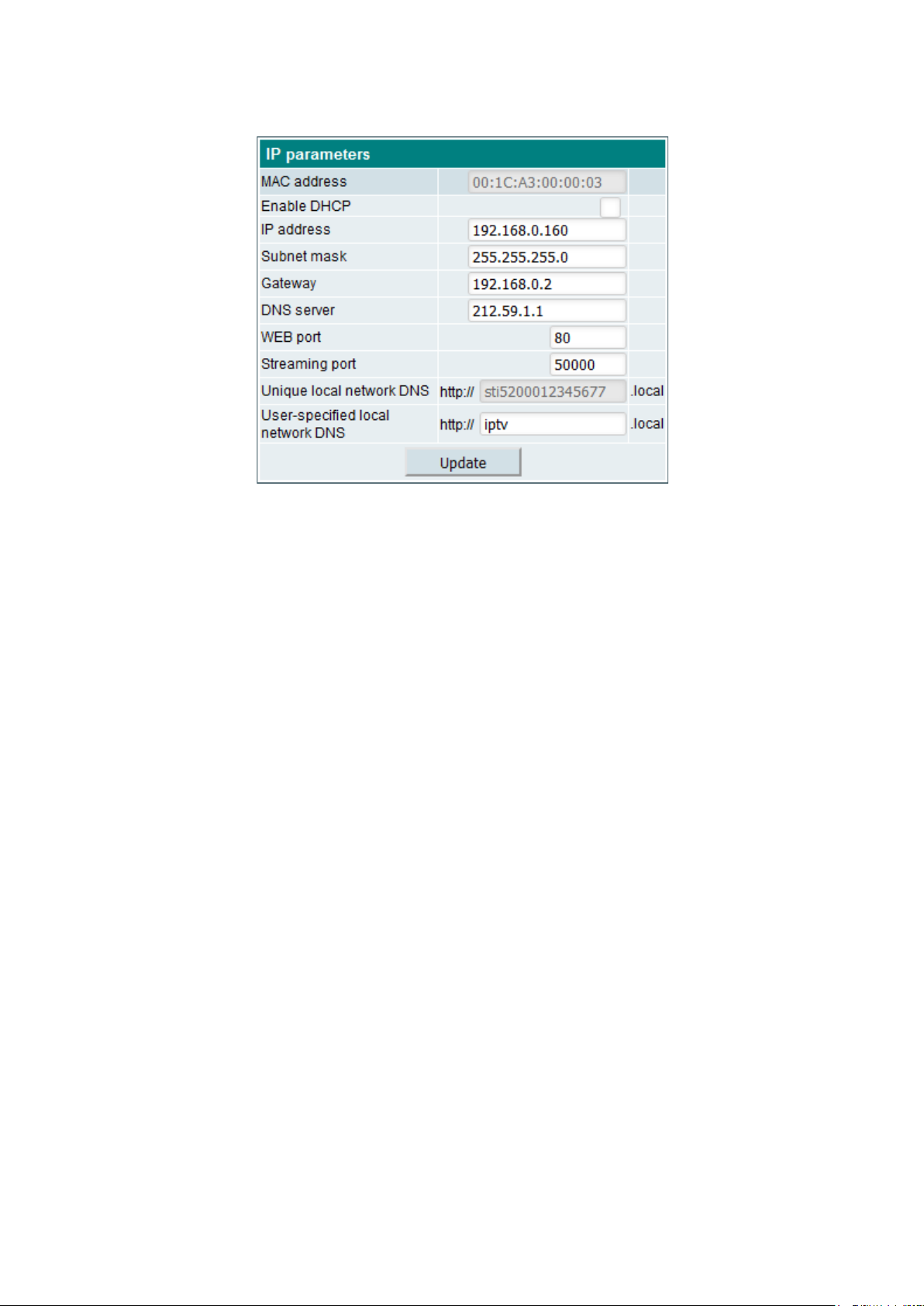
Figure 17. LAN IP parameters.
IP parameters can be set in this section as shown in Figure 17.
Selecting the “Enable DHCP client” checkbox will use a home router’s DHCP server to automatically assign
the IP settings (IP address, subnet mask, gateway, DNS server). Leave check box unchecked if you want to set
“IP address”, “Subnet mask”, “Gateway”, “DNS server” manually. Application will restart if IP address is changed.
“WEB port” is the port number of the control interface. Default value is 80. DO NOT change it unless you
really need having different WEB port number other than 80. If you accidentally change it and can no longer
access the control interface, use the “IP reset” feature by pressing and holding the Reset button on the device
back panel. Read section 6 for more information.
“Streaming port” is the port number of the streaming port. Full system restart is required if this port is
changed.
Device supports mDNS (Multicast DNS) protocol to access it at domain name instead of IP address. The
.local domain name extension is used for such domain names and is only available on the local network.
There are two domain names used to help you accessing the device WEB control interface.
“Unique local network DNS entry” is unique device domain name in the local network. You can access the
device using this unique address entry even if there are multiple steamers in the same network. Use the following
domain name:
http://<serial>.local
Where <serial> is the unit’s 16 symbols length serial number located on the label of the bottom device side.
You can see the example of such URL in the figure 17.
“User-specified local network DNS entry” – user assigned domain name for accessing the device WEB
control interface. Ensure that only one device exists in the same network with the same user specified local
network DNS entry. Otherwise accessing the WEB control interface by address http://iptv.local (or other user
assigned name) will not work.
Be sure to prefix the domain name with http:// as some browsers may simply redirect you to a search engine.
This protocol is supported by Windows and macOS, iOS. It is NOT supported on Android and Linux.
5.6.2 Remote access
Device supports UPnP router management so that the router can be configured to allow remote connections
just with a single click.

11
Figure 18. UPnP router management.
„Local port“ is the device internally used port.
„External port“ is a port number used to access the device remotely or receiving video streams.
“Streaming port” is a port number used for video streaming. External streaming port value should be equal to
local streaming port value. Otherwise “Terra TV” app or third-party video players may not work correctly.
„WEB port“ is the device control port number. Enable this port to access the device WEB interface remotely.
Also enable this port to use “Terra TV“ Android app remotely.
The “Debug port” can only be used if you have a problem and ask the Support for help to resolve it.
Otherwise, keep it off.
An “External IP address” is an IP address which can be used to access the device remotely. When you start
your device for the first time, it will try to set this address automatically (connection to the internet is required).
Also, after successful UPnP configuration, this IP address is read from the router. You can change this IP
address manually if you think the value displayed here is incorrect.
NOTE: use the following IP address template to access the device remotely:
http://<external_IP_adress>:<external_WEB_port>
When you click the “Update”, the device will try to enable / disable the selected ports on network router. The
status indicator icons will show the progress of the operation. Hovering over the status icon will display more
status information.
5.6.3 HTTPS
The user interface of the device can be accessed via the secure HTTPS protocol. Requirement for HTTPS:
• Device must have internet access to automatically renew the certificate;
• Device must be accessed using a domain URL (not IP address);
Domain name created for each device contains the unique serial number. See “HTTPS URL” in Figure 19.
Use this field’s value to access the device securely.
Figure 19. HTTPS configuration.
The domain name points to the local IP address of the device (it is not necessary to have a public IP
address). This secure access feature works even if DHCP client is used. As soon as device IP address is
changed, the DNS records of the domain name are changed automatically. An hour or more may be required for
updates of these records for your internet provider.
The SSL certificate is valid for 3 months and is automatically issued for the device domain and will be
renewed automatically. Default HTTPS port 443 is used for a secure connection, but can be changed by the user.

12
Domain can also point to the public IP address as well (see DNS type parameter in the Figure 19). Additional
router forwarding is required.
“Force redirection” flag will automatically redirect your WEB browser to a secure connection, even if you try to
access it using an IP address. Otherwise, secure connection link will be displayed on the login page for simpler
access.
NOTE: If the redirection fails for any reason (certificate expired, incorrect router forwarding, etc), forced
redirection can be disabled by adding a question mark after the URL. For example: http://192.168.1.10/?
5.7 System menu
This menu provides additional system parameters related to the system management. Depending on the user
access rights, some items in this menu may not be available.
5.7.1 Event logs
Various important events, errors, warnings will be displayed the system log (see Figure 20). Each record has
its own type that can be used to filter only certain messages.
Figure 20. Logs filtering.
Just check the “Logs filtering” checkboxes. Messages will be filtered automatically. The “Erase logs” button
will delete all logs from the system.
The “Download” button creates a logs.json file that can be used for troubleshooting and receiving help from
Support. Messages will be exported in English language regardless of the WEB interface language used.
Figure 21. Logs messages
5.7.2 Change password
The user who wants to change the password must select the “Change password” submenu. The “Change
password” pop-up window will appear as shown in Figure 22.
Figure 22. Change user password.
The special username “admin” cannot be changed. All other usernames can be changed in the “Username”
field. Before setting a new password, the user must enter the current password in the “Current Password” field.
Clicking the “Update” will apply the changes.
5.7.3 Users management
13
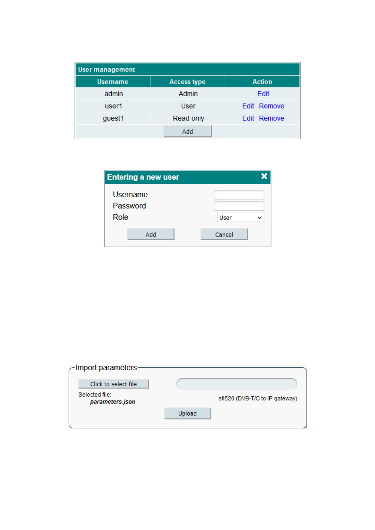
A user with “Administrator” privilege can see this menu and add / remove users who can log in to the system.
Figure 23 shows the users control window.
Figure 23. Users management.
Click “Add” to create a new user. A new pop-up window as shown in Figure 24 will appear. The Role
parameter is a type of user access rights. You can select “Administrator”, “User” or “Guest”.
Figure 24. Entering a new user.
“Admin” user has no restrictions. “User” is almost the same as “Admin”, but user management is disabled.
“Guest” has read-only access which means no device settings can be changed.
A user with administrator access rights can edit another user’s password or change the role. Click “Edit” and
change the parameters. Click “Remove” to remove the user. A confirmation prompt will appear asking if you
really want to remove the user.
5.7.4 Export parameters
Settings of device can be imported and exported from one device to another. You can also create a backup of
your current settings and save to a file. Click the submenu item “Export settings” and select the file path where
the settings should be saved. If you have multiple devices, it is recommended to rename the exported file and
give a clear description to file name.
5.7.5 Import parameters
Exported settings can be imported from one device to another or to the same device. Device type must
match. Click the “Click to select file” button (see Figure 25), select the file you want to import and click “Upload”.
Figure 25. Import parameters.
The WEB interface will check the content of the file as soon as you select the file and prevent the import of
invalid content. If the content of the file are correct, the screen will display the type of device and its description
from which the file was exported. It is also allowed to import settings from one software release to another. Just
keep in mind that a new version of the software may miss some of the previously available settings or have new
additional parameters. In this case, a warning will appear stating that some parameters have not been imported.
14
5.7.6 Firmware upgrade
When you click the “Firmware Upgrade” submenu, your web browser will automatically check for the latest
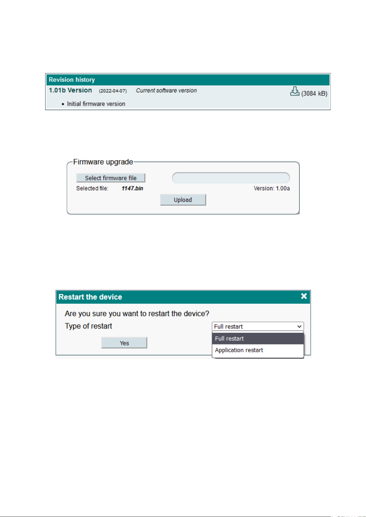
software version. The table (see example Figure 26) with a list of the latest firmware releases will appear on the
screen.
Figure 26. Firmware releases history.
To download the firmware from the server to your computer, click on the “download” icon (indicated by an
arrow in the picture). Note that “Current software version” text will be shown if the device already has this
firmware version. Various notes will be provided here for each firmware release. Notes will be written in English
only, regardless of language choice. After downloading the firmware file, click the “Select firmware file” button in
the Firmware upgrade table (see Figure 27).
Figure 27. Firmware upgrade.
If valid firmware files have been selected, the firmware version number will be displayed as shown in Figure
27. Click the “Upload” button to upload the file to your device. A confirmation message will appears on the screen
asking you to reboot the device. Do not disconnect the power supply from the device during programming. The
login window will appear on the screen as soon as the firmware update is completed. No need to refresh the
browser. All device settings will remain unchanged.
5.7.7 Restart device
The device can be restarted by selecting the “Restart the device” submenu. A confirmation message, shown
in Figure 28, will appear on the screen asking if you really want to do this.
Figure 28. Restart the device.
There are two types of restart – full or application restart. “Full restart“ means that the whole system will be
restarted. Application restart option takes less time, but will restart main application only. After confirmation, the
device will restart. As soon as the device is ready, a login window will appear on the screen.
5.7.8 Auto restart
The device can restart automatically at specific time. Check “Enable” check box, set restart time and choose
what type of restart you want to use. Click the “Update” button to save the changes.

15
Figure 29. Device auto restart.
5.7.9 Restore defaults
All settings, except IP parameters, can be reset to factory defaults by selecting the “Restore defaults”
submenu. A confirmation message will appear on the screen asking if you really want to do this. Once confirmed,
settings will be restored to their default values, and all logs will be deleted.
5.7.10 Language, country
When you click the “Language, country” submenu, a pop-up window as shown in Figure 2 will appear,
prompting you to select the language, country, and region where your device is located. Incorrect country
selection can affect the time zone and other important settings. Make sure this setting is set correctly. DST
means that the time zone contains winter and summer time, which will be selected automatically according to the
country that you chose. In the future, governments may change the time reversal rules, or the time zone of the
region. Inform the manufacturer of this device if the time zone information is incorrect.
5.7.11 Date, time
It’s important that the device has the correct time selected. Recording schedules is affected by the system
time. Figure 30 shows the two NTP servers as a date / time source.
Figure 30. Date and time settings.
”Local Time” shows the time of the device that it currently has, estimating possible DST offset. If the time in
this field is not correct, make sure you select the correct country (see section 5.7.10). Date and Time Source has
two options: NTP Server and Manual Input. In case of an NTP server, at least one server URL must be specified.
Make sure the IP settings (section 5.6.1) are correct and the device can access the NTP server. After clicking
“Update”, the device will try to connect to the server and update the local system time. The device will
synchronize the time automatically later on.
“Manual input” option can be used for testing only, because it will never be synchronized to any external time
source and the time will be reset if the power supply will be disconnected.
5.7.12 Device information
Information about the device is shown in this submenu table (see Figure 31). You can check software version,
time and other useful information about the system.
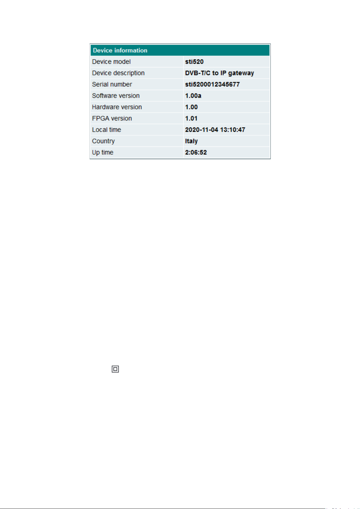
16
Figure 31. Device information.
6. Reset button
Reset button has different functions which mainly depend on the duration of the press.
• Device reset
A short press (less than 2 seconds) will restart the entire system. Red-green LED indicates acceptance of this
command. This corresponds to the section 5.7.7 “Restart the device - Full restart“ function.
• IP reset
Pressing the button for 2-5 seconds will activate the IP reset function. A flashing red-green LED will indicate an
activated IP reset command. It will enable the DHCP option (device IP address will be assigned by network
router) or set the address to 192.168.1.10 if router does not exists. WEB interface port will reset to default value
80. A full reboot of the device will then be performed.
• Restore defaults
Pressing the button for longer than 7 seconds will activate the “Restore defaults“ function. Red blinking LED will
indicate an activated command. After releasing the button, all device parameters will be restored to their default
values, and application will be restarted. IP settings will not be restored to defaults.
• Restore firmware to factory version
This command is intended for use in critical situations where it is not possible to use other recovery method. The
command will delete all files from the device and restore the original application from read-only memory. All
firmware upgrades will be lost, so you will need to perform the “Firmware upgrade” (section 5.7.6) function to
have the latest software version. Firstly the device must be powered off to call this function. Press the “Reset”
button and turn on the power. Hold down the button for a few seconds until the LED starts flashing. When it starts
flashing, keep it pressed further for 3 seconds until the red-green LED lights up. After this point, releasing the
button will start the deletion procedure.
7. REQUIREMENTS FOR EXTERNAL POWER SUPPLY UNIT
• Output voltage +12 V ± 1V
• Output current ≥ 1.0 A
• Ripple at single and/or double mains frequency ≤ 10 mV p-p
• Ripple and noise ≤ 180 mV p-p
• Output connector type 3.5/1.3 (+) plug
• Short circuit protection
• Double insulated (marked )
• Meet EN55022 class B conducted emissions requirements, measuring with grounded load

17
8. Technical specifications
RF input
tuners count
2
DC output for antenna
preamplifier
12 V 100 mA
frequency range
47-862 MHz
AGC range/impedance
45-80 dBμV / 75 Ω
standard
DVB-T
DVB-T2
DVB-C
modulation
QPSK, QAM16,
QAM64
QPSK, QAM16,
QAM64, QAM256
QAM16, QAM32,
QAM64,
QAM128, QAM256
channel bandwidth
7 MHz/8 MHz
7 MHz/8 MHz
-
symbol rate
-
-
1 ÷ 7.2 Ms/s
code rate
1/2, 2/3, 3/4, 5/6,
7/8
1/2, 3/5, 2/3, 3/4,
4/5, 5/6
-
roll off
-
-
15 %
Storage
network disk
CIFS, SMB
USB disk
FAT32, NTFS, exFAT, EXT3, EXT4
max. disk size
4 TB
USB
standard
USB 2.0
connector type
USB-A
DC output
5 V 500 mA
IP output
standard
IEE802.3 10/100 Base T
bit rate
up to 80 Mbit, including recordings
supported protocol
DLNA, HTTP, SRT
number of users
4*
MPTS
No
SPTS
Yes
Control port
standard IEE802.3 10/100 Base T
Current consumption without external
load
12 ± 1 V 300 mA (STI520)
Current consumption with max. external
load
12 ± 1 V 700 mA (STI520)
Supply voltage limit values, power
consumption
100-240 V~ 50/60 Hz 10 W max. (STI520P)
Operating temperature
0º C ÷ +50º C
Dimensions/Weight (packed)
112x35x124 mm/0.24 kg (STI520)
112x35x124 mm/0.34 kg (STI520P)
Package contents
1.
Streamer
……………………………..
1 pcs
2.
External power supply
……………………………..
1 pcs (for STI520P ordering number only)
3.
Quick start guide
……………………………..
1 pcs
4.
Safety instruction
……………………………..
1 pcs
5.
Adapter for 5.5/2.1 mm DC jack
……………………………..
1 pcs (for STI520 ordering number only)
Draugystes str. 22, LT-51256 Kaunas, Lithuania, tel.: +370 37 - 31 34 44, fax: +370 37 - 31 35 55
E-mail: sales@terraelectronics.com,http://www.terraelectronics.com
Other manuals for STI520
1
Other Terra Media Player manuals


