TerraKing 45-0592 User manual
OPERATOR’S MANUAL
5 cu ft Drop Spreader
45-0592 and 45-0593
04/05/22
For your safety, please read and save all
safety and operating instructions prior to
using equipment.
GREY
PMS 427
CMYK C19 M15 Y16 K0
RGB R204 G204 B204
Hex #CCCCCC
Threa Light Ash
BLUE
PMS 647
CMYK C91 M60 Y4 K0
RGB R20 G103 B172
Hex #1268AC
Thread Farm Blue
ORANGE
PMS 715
CMYK C0 M69 Y98 K0
RGB R243 G113 B33
Hex #F37121
Thread Tennessee Orange
BLACK
PMS TBD
CMYK C0 M0 Y0 K100
RGB R0 G0 B0
Hex #000000
Thread Black
GREY
PMS 428
CMYK C27 M17 Y17 K0
RGB R195 G197 B200
Hex #c3c5c8
Thread Light Gray
BLUE
PMS 287
CMYK C100 M87 Y20 K10
RGB R32 G61 B124
Hex #203d7c
Thread Dark Royal
GOLD
PMS 3965
CMYK C1 M14 Y99 K0
RGB R254 G212 B2
Hex #231f20
Thread NFL Yellow

2
Read Safety in Machine Operator’s Manual
Read the general safety operating precautions in
your machine operator’s manual for additional safety
information.
Operating Safely
• Read the machine and attachment operator’s manual
carefully. Be thoroughly familiar with the controls and
the proper use of the equipment. Know how to stop
the machine and disengage the controls quickly.
• Do not modify machine or safety devices.
Unauthorized modications to the machine of
attachment may impair its function and safety.
• Do not let children or an untrained person operate
machine.
• Make any necessary adjustments before you operate.
Never attempt to make any adjustments while
the engine is running, unless if recommended in
adjustment procedure.
• Look behind machine before you back up.
Back up carefully.
• Do not let anyone, especially children, ride on
machine or attachment. Riders are subject to injury
such as being struck by foreign objects and being
thrown o. Riders may also obstruct the operator’s
view, resulting in the machine being operated in an
unsafe manner.
• Disengage any power to the attachment when the
machine is transported or not in use.
• Never exceed 15 mph when loaded spreader is
attached to vehicle. Braking distances may be
reduced and handling characteristics may be impaired
at speeds above 15 mph.
• Never use wet materials or materials with foreign
debris in the spreader. This unit is designed to spread
dry, clean, free-owing material.
• Never leave material in hopper when not in use.
Practice Safe Maintenance
• Only qualied, trained adults should service this
machine.
• Understand service procedure before doing work.
Keep area clean and dry.
• Do not operate the engine in a conrmed space where
dangerous carbon monoxide fumes can collect.
• Never lubricate, service or adjust the machine or
attachment while it is moving. Keep safety devices in
place and in working condition. Keep hardware tight.
• Keep hands, feet, clothing, jewelry, and long hair away
from any moving parts, to prevent them from getting
caught.
• Lower any attachment completely to the ground or
to an existing attachment mechanical stop before
servicing the attachment. Disengage all power and
stop the engine. Lock park brake and remove the key.
Let machine cool.
• Disconnect battery or remove spark plug wire (for
gasoline engines) before making any repairs.
• Before servicing machine or attachment, carefully
release pressure from any components with stored
energy, such as hydraulic components and springs.
• Release hydraulic pressure by lowering attachment or
cutting units to the ground or to a mechanical stop and
move hydraulic control levers.
• Securely support any machine or attachment
elements that must be raised for service work.
Use jack stands or lock service latches to support
components when needed.
• Never run engine unless park brake is locked.
• Keep all parts in good condition and properly installed.
Fix damage immediately. Replace worn or broken
parts. Replace all worn or damaged safety and
instruction decals.
• Check all hardware at frequent intervals to be sure the
equipment is in safe working condition.
• Do not modify machine or safety devices.
Unauthorized modications to the machine or
attachments may impair its function and safety.
Wear Appropriate Clothing
• Always wear eye protection when operating the
machine.
• Wear close tting clothing and safety equipment
appropriate for the job.
• Wear a suitable protective device such as earplug.
Loud noise can cause impairment or loss of hearing.
Safety

3
Read Chemical Container Label
• Chemicals can be dangerous. Improper selection or
use can injure persons, animals, plants, soils or other
property. Select the right chemical for the job and
handle and apply with care.
• Read the instructions, precautions, and warnings on
the container label before opening. Use the product
strictly according to label directions for specic
applications, in the amounts specied, at the times
specied and only when needed.
• Keep the container closed tightly except when
preparing the mix.
• Do not remove labels from chemical containers. Store
all chemicals in their original containers.
• Do not mix chemicals unless stated on the container
label.
• Store chemicals when not in use according to the
container label.
Handle Chemical Products Safely
• Direct exposure to hazardous chemicals can cause
serious injury. Potentially hazardous chemicals used
with equipment include pesticides, herbicides and
fungicides.
• A Material Safety Data Sheet (MSDS) provides
specic details on chemical products: Physical and
health hazards, safety procedures, and emergency
response techniques.
• The MSDS should be obtained from the chemical
dealer at the time of the chemical purchase.
• Check the MSDS before beginning any job using a
hazardous chemical. Know exactly what the risks
are and how to do the job safely. Always wear
recommended personal protection equipment.
Handling Waste Product and Chemicals
Waste products, such as, used oil, fuel, coolant, brake
uid, and batteries, can harm the environment and people:
• Do not use beverage containers for waste
uids - someone may drink from them.
• See your Recycling Center or authorized dealer to
learn how recycle or get rid of waste products.
• A Material Safety Data Sheet (MSDS) provides
specic details on chemical products: Physical and
health hazards, safety procedures, and emergency
response techniques. The seller of the chemical
products used with your machine is responsible for
providing the MSDS for that product.
Safety

4
Safety
Safety Labels
Safety Label Location
350 lbs
ST50400
TO AVOID INJURY,
DO NOT RIDE
ON PLATFORM
ST50569
Understanding The Machine Safety Labels
The machine safety labels shown in this
section are placed in important areas on
your machine to draw attention to potential
safety hazards.
On your machine safety labels, the words DANGER,
WARNING, and CAUTION are used with this safety-alert
symbol. DANGER identifies the most serious hazards.
The operator’s manual also explains any
potential safety hazards whenever necessary
in special messages that are identified with the
word, CAUTION, and the safety-alert symbol.
Replace missing or damaged safety labels. Use this
operator’s manual for correct safety label placement.
There can be more safety information contained on
parts and components sourced from suppliers that is
not reproduced in this operator’s manual.
French or Spanish Safety Labels and
Operator’s Manual
Operator’s manuals and safety labels with content in
French or Spanish are available for this machine through
authorized John Deere dealers.
Warning
Avoid Injury From Moving Parts
• Keep hands, feet and clothing away
• Disconnect power before servicing

5
Parts in Kit
Wiring Kit
The serial number label (A) is located on the lower front
right side as shown above.
Machine Requirements
2” Receiver
Maximum drop spreader weight is 540 lbs. Vehicle’s
receiver hitch must be rated accordingly to prevent
damage to vehicle and drop spreader.
3 Point Hitch
Requires category 1 three point hitch. If no front
attachment is installed on vehicle, ballast may be
required to stabilize vehicle. Refer to vehicle manual
for proper ballasting.
A
Qty Description
1 Spreader
Qty Description
1 Display
1 Battery Harness
1 Extension Harness
1 Display Harness
1 Mounting Bracket
1 P Clamp
Caution
Avoid Injury and Read Operator Manual Before Use
• Never remove spreader with material in hopper
• Maximum weight capacity 350 lb.
Caution
To Avoid injury, do not ride on platform
Safety Labels
ST50569
350 lbs
ST50400
6
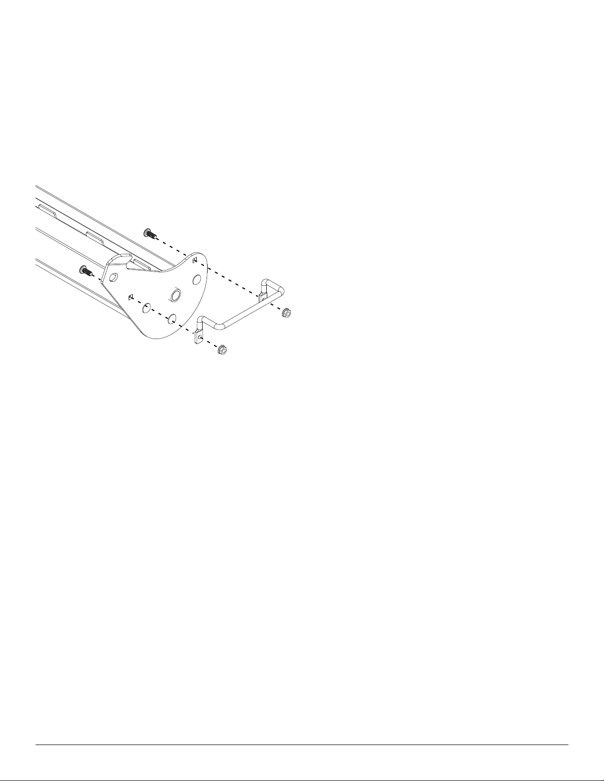
Install Handle
1. Locate handle and hardware inside the parts bag
2. Attach handle to outside of Auger tray with the bolts
inserted from the inside and flange nuts on the outside as
shown in Figure 1
3. Tighten hardware using ½” wrench or socket
Install Display and Wiring
Mount display in a location that is convenient for the
operator using either the included bracket, p-clamps or
M5 screws and washers.
Starting at the battery, connect the ring terminals on
the battery harness to the battery (red positive, black
negative). Connect extension harness to the battery
harness and route the extension harness towards the
3 point hitch or 2” receiver securing the harness to the
vehicle along the way. ensure the harness does not
contact any moving or high temperature components.
Secure the connector on the free end of the extension
harness in the convenient location that is easily accessible
in order to connect/disconnect the spreader. Coil any extra
harness and secure with wire ties.
Connect the circular connector on the display harness to
the rear of the display. Hand tighten until is fully seated.
DO NOT over tighten/ DO NOT cross thread. Route the
display harness to the same location as the free end of
the extension harness. Coil any extra harness and secure
with wire ties.
Installing
Locate a 12V signal / circuit that is behind the key switch
(only powered when the key is turn to run or acc). Route
the single wire in the display harness to this location and
secure to the vehicle along the way with wire ties. Extra
harness can be removed or coiled and secured with
wire ties. Connect the single wire to the circuit using a
suitable connection. A wire splice is included in the kit for
convenience.
Mount Spreader to Vehicle
Mount the spreader to the 3 point hitch or 2” receiver.
Use the handles located on the hopper side panels to lift
into position and secure in place. It is recommended that
2 people lift the spreader into place.
Connect the 2 connectors on the harness attached to the
spreader to the free end of the extension harness and
display harness.

7
Spreader Feature
Turning On Display
The vehicle key must be in the “On” or “Run” position for
the display to turn on.
When turned on, a splash screen will appear as the
software loads. The operation page will appear when
loading is complete. The spreader is now ready to operate.
Navigation
Control the spreader using the buttons on the display.
Button functionality is described in the table below and
varies by screen.
Operation
Auger Reverse/Jam Clear
Error Message/Diagnostics
Vibratory motor for improved material ow
Variable Speed Auger
Adjustable gate for precise material application
From the operation page, an operator can power on the
spreader, enter the menu, or spinner speed.
Button # Button Functions
1ON Spinner/
Auger On
Press the “ON”
button to turn on the
auger.
2OFF Spinner/
Auger O
Press the “OFF”
button to turn o the
auger.
3OPEN/
ON
Gate Open/
Vibe ON
Press the OPEN/ON
button to turn on the
vibratory motor.
4CLOSE/
OFF
Gate
Close/Vibe
OFF
Press the CLOSE/
OFF button to turn o
the vibratory motor.
5Down
Arrow
Press to decrease
the speed of the
auger.
6Up Arrow Press to increase the
speed of the auger.
7MENU Menu
Button
Press to enter the
menu.

8
NOTE: In order to control the Gate/Vibratory Motor
the Spinner/Auger must be active, if it is not active the
Gate/Vibe label state will blink indicating the motor is
disabled.
Main Menu
Pressing the menu button will enter the main menu.
Once in the main menu, the user can select the following:
Operation
Default Motor Controls
Starting and
Stopping Spreader
Press the ON button to turn on
the spinner/auger.
Press the OFF button to turn o
the spinner/auger
Gate/Vibe Control Press the OPEN/ON button to
open the gate or to turn on the
vibe.
Press the CLOSE/OFF button to
close the gate or to turn o the
vibe.
Adjusting Motor
Speed
Press the bottom left button
(down arrow) to decrease the
speed of the motor in 11%
increments.
Press the bottom mid button (up
arrow) to increase the speed of
the motor in 11% increments.
Entering the Menu Press the bottom right button
(menu) to enter the menu.
Maintenance Menu
Reverse Auger
The reverse auger feature allows users to reverse the
auger in case of a jam.
To activate the reverse auger feature:
1. Select maintenance for the main menu.
2. Press start. The auger will pulse 3 times and the start
button changes to pulsing to indicate the auger is
turning.
3. If the auger needs to be reversed further, press start
again and wait for the reverse cycle to complete.
4. Press the exit button to return to the main menu.
5. If jam cannot be cleared, refer to cleaning auger
section
Menu Options
Diagnostics Review the warning and fault list.
Maintenance Displays maintenance menu with
options to reverse auger.
Settings Adjusts the parameters of the display.
System Display system’s voltage and
temperature.
Support Displays support information.
Controller Info Displays controller information
Display Info Displays system information.
Exit Returns to the home page.
9
Display Screen Messages
During operation a message may appear describing a
potential issue or problem.
Motor Over Current A motor is drawing too
much current. Spreader will
shut down, display an error
message, and prompt the
operator to reset the spreader.
The spinner disk may be
jammed and needs to be
cleared.
Motor Open Circuit This message is displayed
when a motor is disconnected.
Ensure that all harnesses
are installed correctly, and
connectors are fully seated.
Ensure that the status light on
the motor controller is green.
Voltage High This message is displayed
when the controller is receiving
a voltage higher than 16V.
Please check battery voltage.
Voltage low This message is displayed
when the controller is receiving
a voltage lower than 9V. Please
check battery voltage.
No Comm This message is displayed
when there is a loss of
communication with the
motor controller. Ensure that
all harnesses are installed
correctly, and connectors
are fully seated. Ensure that
the status light on the motor
controller is green.
Spreading
NOTE: Always use the hopper cover to prevent moisture
buildup. Do not let spreader sit idle with material in the
hopper for an extended period of time. This can cause
material to compact, reduce or stop the ow of material and
cause permanent hopper damage.
CAUTION: DO NOT leave unused material
in hopper. Material can freeze or solidify,
causing unit to not work properly. Empty
and clean after each use.
IMPORTANT: Never operate near pedestrians.
Never exceed 10 mph while spreading. This
spreader is for rock salt, ice melt, fertilizer or
lime only.
CAUTION: Disconnect electric and/or
hydraulic power and tag out if required
before servicing or performing maintenance.
Settings Menu
Selecting settings from the main menu will enter the
settings menu.
From the settings menu, the user can select the following:
• Display to select the brightness level.
• CAN, to enable/disable the CAN terminator resistor.
• Exit, go back to main menu.
Operation
10
To calculate application rate
• Determine the vehicle speed that will be used.
• Place the container on a scale and make note of the
weight or tare the scale.
• Measure the weight / mass of the material spread
in 30 seconds. Subtract the weight / mass of
the container.
• Divide lbs measured in 30 seconds by the intended
speed of the vehicle in mph, and multiply by 6.06 to
get lbs per 1000 ft².
Metering Gate Adjustment
To adjust the opening on the metering gate, squeeze
lever(A) downward and rotate handle(B) to desired
opening. There are 6 gate positions, each position
increments the gate by approximately 1/4”.
Preventing and Clearing blockages
Material flows best when material is free of large clumps.
If a blockage occurs or material is not spreading, proceed
with the following steps until the blockage is cleared.
1. Open the metering gate to a larger position and
attempt to spread material again.
2. Turn on the vibrator to help break apart any clumps
of material and help the material to flow into the rotor
tray. Attempt to spread again.
3. If the rotor is stalled and jammed. Disconnect the
spreader harness from the control box. Follow the
steps in the cleaning the rotor section.
4. Disconnect power from the spreader. Remove lid and
open top grate. Remove any clumped material from
the hopper
Maintenance
Before performing any maintenance, turn off the spreader
and park machine safely (see Parking Safely in the
Safety section). Unplug the spreader harness from the
control box.
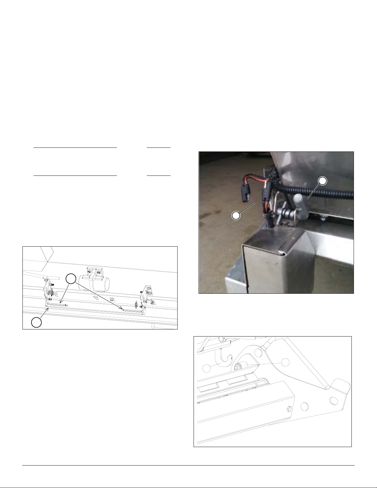
Cleaning Rotor
To clean the rotor area, do not reach down from the top of
the machine. The tray housing the rotor is removable.
1. Disconnect the power cord (A) to the drive motor.
2. Lock out the pins (B) on both sides of the machine.
When the second pin is pulled, the rear of the
tray will drop.
NOTE: It is recommended two people remove the
rotor assembly
3. Lift pivot bolts (C) off the hooks (D) and the rotor can
be removed for cleaning. (Left side shown above)
Operation
A
B
lbs per 30 seconds
intended vehicle speed in mph
lbs
1000ft2
x 6.06 =
kg per 30 seconds
intended vehicle speed in kmph
kg
1000m2
x 3.5 =
A
B
C
D

11
Adjusting Chain Tension
4. Remove bolt (E) and lift bottom of shield until it is
rotated about 90° and pull out.
5. Loosen three bolts (F) and slide the motor mount plate
rearward. The slack-side (G) tension should be 1/4” to
5/16” (6mm to 8mm) of midspan movement.
Re-tighten three bolts.
Chain Lubrication
Schedule chain lubrication:
• Apply lubrication upon removal from storage
• Reapply lubrication every 20 hours of use
• Apply lubrication prior to storage
Cleaning
To protect from corrosion, clean spreader after every use
with warm water and mild detergent.
Do not leave material in the spreader.
Maintenance
E
1/4” to 5/16”
F
G
Volume...................................................5 cu ft (.14 cu m)
Material Capacity.....................................350 lbs (159 kg)
Weight (empty, 3 point)..............................191 lbs (87 kg)
Weight (empty, 2” receiver)........................180 lbs (82 kg)
Weight (maximum, full)............................540 lbs (245 kg)
Weight of rotor tray.......................................48 lbs (22 kg)
Width..........................................................49 in (125 cm)
Depth (3 point)..............................................25 in (64 cm)
Depth (2” receiver)........................................31 in (79 cm)
Height...........................................................28 in (71 cm)
Spreading Width.........................................43 in (109 cm)
Electrical........................................................12 volt / 25A
Specifications
12
2
3
4
6
10
5
11
8
7
11
10
1
9
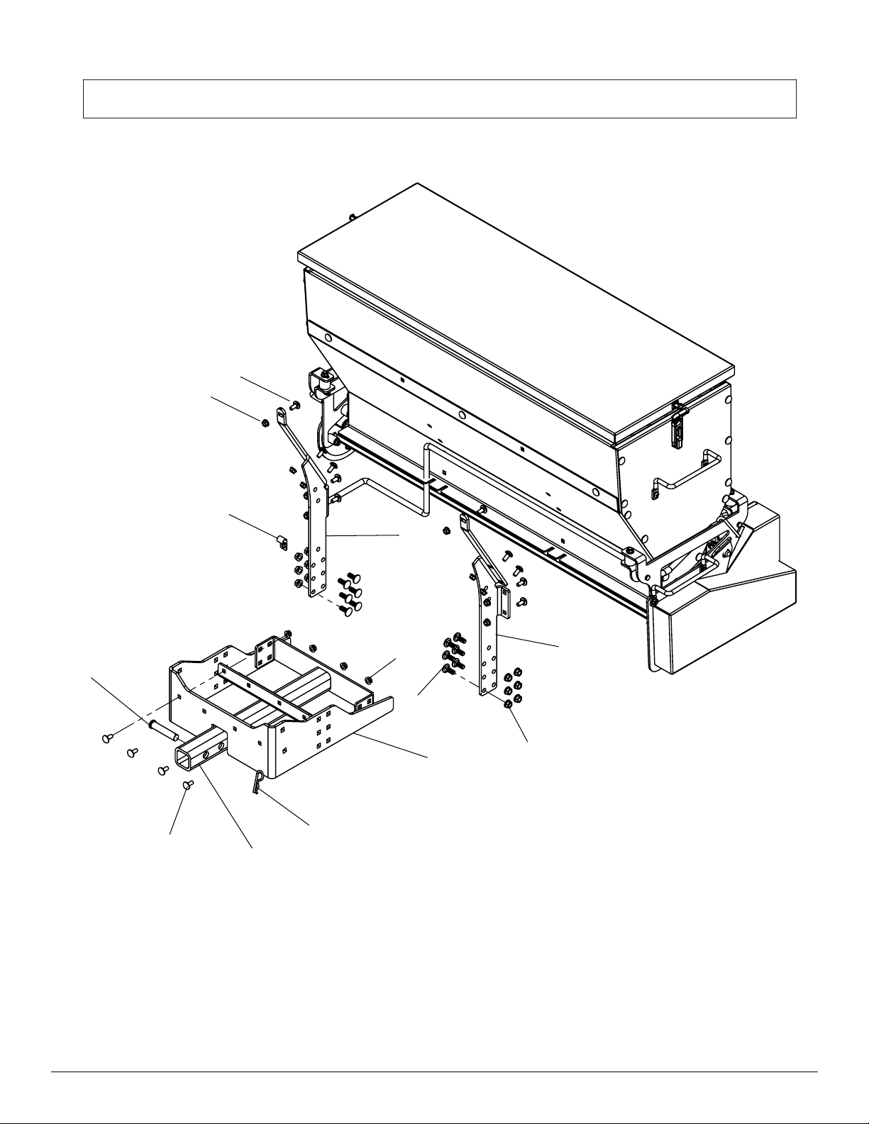
45-0593 Drop Spreader 2-In. Receiver

13
ITEM NO.
PART NUMBER
DESCRIPTION
QTY.
1
ST50454
Leg, Frame
1
2
ST50455
Leg, Frame
1
3
ST50533
Base, Regular profile
1
4
ST50531
2" Receiver Assembly
1
5
ST50373
Clevis Pin ø5/8" x 3"
1
6
ST43469
Spring Cotter Pin
1
7
ST50468
Clamp, 1/2"ID x .75W Vinyl Coated
1
8
ST65136
Bolt, 3/8" x 1" Carriage S.S.
12
9
ST65126
Nut, 3/8" Flange S.S.
12
10
ST65122
Bolt, 5/16" x 3/4" Carriage S.S.
14
11
ST65124
Nut, 5/16" Flange S.S.
14
Not Shown
ST50306
Spreader Safety Label
2
Not Shown
ST50400
Read Manual Label
2
Not Shown
ST50569
Do Not Ride Label
1
Not Shown
ST50251
TerraKing Label
1
Not Shown
ST50552
Reflective DOT-C2 Tape
2

14
45-0592 - Drop Spreader with 3-Pt. Hitch Mount
3
7 8
4 5
10
2
1
6
11
12
9
13
14
15
17
16

15
45-0592
REVISION HISTORY
Rev. B 03/24/2022
ITEM NO.
PART NUMBER
DESCRIPTION
QTY.
1
ST50454
Frame, Right Leg
1
2
ST50455
Frame, Left Leg
1
3
ST61500
3 Point Hitch A Frame
1
4
ST50533
Frame Base
1
5
ST50527
Frame Spacer
2
6
ST50464
3 Point Hitch Brace
2
7
ST43399
Top Pin, Cat 1
1
8
ST43398
Lynch Pin
3
9
ST50468
Clamp, 1/2"ID x .75W Vinyl Coated
1
10
ST65135
3/8" x 1-1/4" Carriage Bolt S.S.
4
11
ST65136
3/8" x 1" Carriage Bolt S.S.
16
12
ST65126
Nut, 3/8" Flange S.S.
20
13
ST65122
Bolt, 5/16" x 3/4" Carriage S.S.
10
14
ST65124
Nut, 5/16" Flange S.S.
10
15
ST50565
SMV Holder Bracket
1
16
ST50583
SMV mounting spade & Hardware
1
17
ST43647
SMV Sign
1
2
2
2
1
Not Shown
Not Shown
Not Shown
Not Shown
Not Shown
ST50552
Reflective DOT-C2 Tape
ST50306
Spreader Safety Label
ST50400
Read Manual Label
ST50569
Do Not Ride Label
ST50251
TerraKing Label
1
16
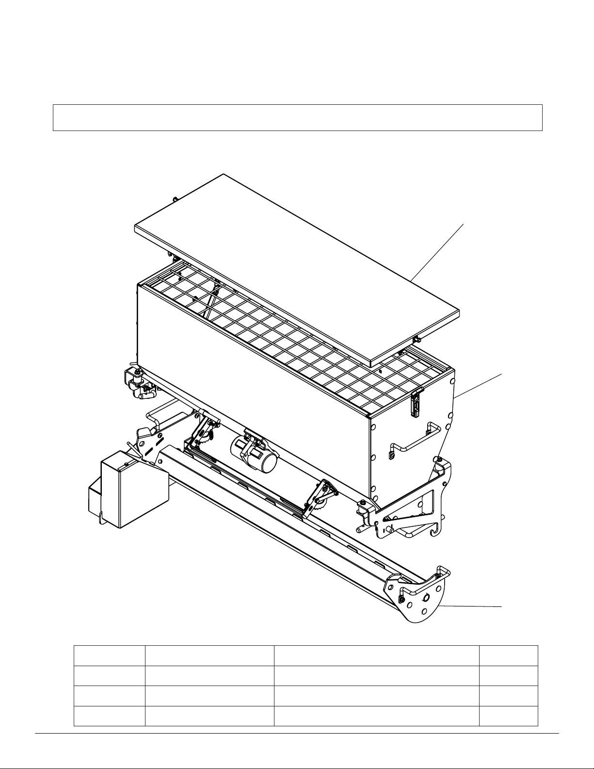
ITEM NO.
PART NUMBER
DESCRIPTION
QTY.
1
SA10018
Hopper Assembly
1
2
ST50478
Tray Assembly
1
3
ST50432
Lid Assembly
1
3
1
2
Drop Spreader Assemblies
REVISION HISTORY
Rev. A 10/27/2021

17
This Page Intentionally Left Blank

18
SA10018 - Drop Spreader Hopper Assembly
7
36
23
22
35
41 39 19
38
28
34
14
13
12
29
11
18
30
40
20
21
19 39
4
9
26
24 15
37
27
10
32
25
5
42
39
17
38 16
1
2
42
33
25
10
6
24
15
26
37
3
8
31
43
44
38

19
Motor Controller
SA10028
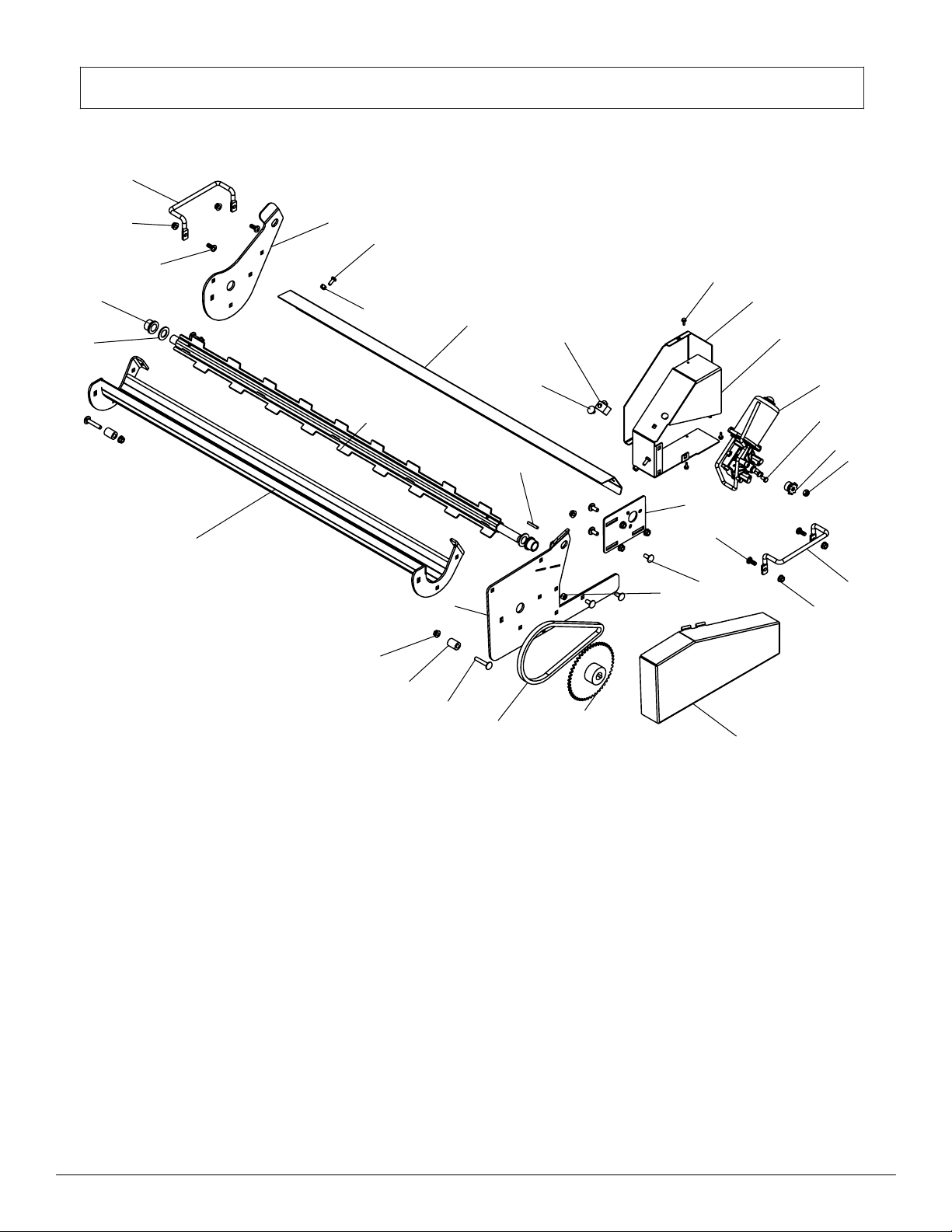
ITEM NO.
PART NUMBER
DESCRIPTION
Standard/QTY.
1
ST50827
Wall, Front Lower Hopper
1
2
ST50410
Wall, Front Upper Hopper
1
3
ST50408
Wall, Left Hopper
1
4
ST50412
Wall, Back Hopper
1
5
ST50409
Wall, Right Hopper
1
6
ST50479
Left Tray Hanger
1
7
ST50480
Right Tray Hanger
1
8
ST50425
Base, Vibration Mount Left
1
9
ST50426
Base, Vibration Mount Right
1
10
ST50447
Handle
2
11
ST50825
Vibrator, 40 Ibf
1
12
ST50557
Gate Handle
1
13
ST50558
Gate Latch Lever
2
14
ST50561
Handle Grip
2
15
ST50360
Spring
2
16
ST50450
Grate
1
17
ST50453
Clip
2
18
ST50449
Spring
2
19
ST50562
Linkage
2
20
ST50559
Selector, Gate Position
1
21
ST50560
Selector, Gate Position
1
22
ST50437
Gate, Flow Control
1
23
ST50436
Shoulder Washer USA
6
24
ST50359
Locking Pin 5/8"dia S.S
2
25
ST50451
Rubber Latch
2
26
ST50423
Rubber Isolator
4
27
ST50424
Rubber Bumper
2
28
ST50468
Clamp, 1/2"ID x .75W Vinyl Coated
3
29
ST65138
3/8" x 1-1/4" S.S Hex Bolt
4
30
ST65127
Nut, 3/8" Nylock S.S.
4
31
ST65146
Cap Screw 5/16" x 1-1/4" S.S.
2
32
ST65137
Pan Head Phil.#4 5/16"-18 x 3/4" S.S.
4
33
ST65121
Bolt, 5/16" x 1/2" Short Neck Carriage S.S
26
34
ST65124
Nut, 5/16" Flange S.S.
47
35
ST65122
Bolt, 5/16" x 3/4" Carriage S.S.
13
36
ST65099
Nut, 5/16"-18 Nylock S.S.
8
37
ST65168
1/4" x 1-1/2" S.S. Hex Bolt
4
38
ST65115
1/4"-20 S.S. Nylon Lock Nut
14
39
ST65120
Bolt, 1/4"-20 x 5/8" Hex S.S.
6
40
ST65148
10-24 S.S. Nylon Lock Nut
4
41
ST65147
10-24 x 3/4" Cap Screw S.S.
2
42
ST65130
10-24 #2 S/S Pan Screw
4
Not Shown
ST50828
Motor Harness
1
SA10018
REVISION HISTORY
Rev. B 03/24/2022
43
1
44
ST65224
1/4” x 1” Hex Bolt S.S.
4
Not Shown
ST50939
Motor Controller Harness
1
Not Shown
ST50832
Plug 120 Ohm
1
Not Shown
ST50833
3 pin Recpt Cap
1
Not Shown
ST80978
3 pin Plug Cap
1
20
9
6
27
24
20
14
17
19
22
8
7
18
6
27
24
3
29
26
4
2
1
27
11
25
16 15
5
10
12
21
23
24
28
13
ST50478 - Drop Spreader Tray Assembly
This manual suits for next models
1
Table of contents
Other TerraKing Spreader manuals


