UNIA TYTAN premium 11 Manual

AGROMET PILMET Sp. z o.o.
ul. Fabryczna 2
PL 49 –301 BRZEG
tel. + 48 77 444 45 86
fax. + 48 77 416 20 83
Tel. helpline + 48 77 444 45
11
www.uniagroup.com
MANURE SPREADERS
TYTAN premium 11; 13; 18
OPERATING AND MAINTENANCE
MANUAL SPARE PARTS CATALOG
Before commissioning the machinery you need to
read and understand the Operating Manual and
follow the safety recommendations included.

Operating Manual
TYTAN premium
- page 1 -
Developed by:
AGROMET PILMET sp. z o.o.
Design Office of
AGROMET PILMET Sp. z o.o. in Brzeg reserves the right to implement structural modifications
into the manufactured machinery, which can facilitate operation and improve work
quality.
Please list any notes and observations on the machinery structure and operation in the
attached
survey, and send it to the manufacturer’s address. They will allow further improvement
and modernization of the manufactured equipment.
Note!
Before you hit public roads you need to attach a vehicle marking plate on the machine’s
rear side.

Operating Manual
TYTAN premium
- page 2 -
TABLE OF
CONTENTS
I.
Work safety principles
- p. 3
II.
Limitations related to traveling on public roads
- p. 4
III.
Aggregation, loading, transportation
- p. 4
IV.
First start-up
- p. 4
V.
General and commercial information
- p. 5
VI.
Safety symbols
- p. 5
VII.
Noise and vibrations
- p. 7
VIII.
Operating Manual
- p. 7
1.
General information
- p. 7
2.
Equipment
- p. 7
3.
Purpose
- p. 7
4.
Technical characteristics of the spreader
- p. 8
5.
Structure and operation
- p. 9
5.
1.
Power transmission system
- p. 9
5.
2.
Floor conveyor
- p. 10
5.
3.
Braking system
- p. 10
5.
4.
Hydraulic installation
- p. 11
5.
5.
Electrical installation and lighting system
- p. 11
6.
Spreader utilization
- p. 13
6.
1.
Machinery preparation and adjustment for work
- p. 13
6.
2.
Coupling the machinery to a tractor
- p. 13
6.
3.
Loading and unloading the trailer
- p. 15
6.
4.
Principles of correct use of the machinery
- p. 15
6.
4.1.
Adjustment of the manure dose
- p. 15
6.
4.2.
Spreading adapter
- p. 15
6.
4.3.
Adjustment of the conveyor chains tension
- p. 17
6.
4.4.
Brakes regulation
- p. 18
6.
4.5.
Drive through jointed shafts
- p. 19
6.
5.
Faults in the machinery operation and their removal
- p. 20
7.
Maintenance and lubrication
- p. 22
8.
Disassembly and withdrawal from use
- p. 23
9.
Manure spreading standard
- p. 24

Operating Manual
TYTAN premium
- page 3 -
INTRODUCTION:
This Operating Manual, provided with the machinery, is intended to inform the user about
correct operation and exploitation of the spreader. Careful observance of the recommendation
included in the Manual will ensure safe and efficient machinery operation. In case of any problems
or doubts related to operation and
exploitation, please contact with an authorized seller or the manufacturer’s Sales Department.
I. OCCUPATIONAL HEALTH AND SAFETY
1. During any works carried out on the spreader’s mechanisms, that are jointed with a tractor
via a shaft, you need to turn the tractor’s engine off and take the key out of the ignition switch.
2. You must not operate or travel on the spreader or its drawbar when covers of mechanisms
and jointed-telescopic shafts are removed. Furthermore, you must not exceed the permitted
speed.
3. You must not leave the spreader on inclined surfaces or slopes without activating a
handbrake and securing the travel wheels with wedges.
4. It is dangerous to remain at the spreader’s back side during its operation as the manure may
contain various items, such us stones, wood, bricks, etc.
5. You need to be careful during any disassembly works, not to cause body injuries. In case of
injury you need to clean the wound immediately, disinfect it with hydrogen peroxide solution
and contact a doctor. An injured sport that is contaminated with manure can lead to infection
with tetanus bacteria.
6. Exceeding a permissible loading capacity can damage the machine and cause an accident
on the road.
7. You must not use the floor conveyor to unload heavy materials, such as rubble, gravel, sand,
etc.
8. Machinery operators shouldbe trained in the scope of applicable OHSand the HighwayCode
principles.
9. You need to observe all recommendations included in the Manual, and take special care in
doubtful cases.
10. Before you hit a public road you need to clean the machinery lights and attach a vehicle
marking plate on its rear side.
11. A manure spreader without a braking system, should be equipped with:
- wedges to be
placed under
wheels,
- security chains - if a spreader’s catch uncouples from the tractor’s
catch,
12. You must not load or unload the spreader (trailer) if it’s not coupled to the tractor.
13. When you go up and down the spreader use the intended safe ladder - with proper length
and location.
14. Whencarrying out assembly and disassemblyactions, you must always place the supporting,
safety devices and ladders in a position guaranteeing operational safety.

Operating Manual
TYTAN premium
- page 4 -
II. LIMITATIONS RELATED TO TRAVELING ON PUBLIC ROADS
The manure spreader is equipped with electric and pneumatic installations. It’s adjusted to
traveling on public roads with a tractor.
There is a bracket for a vehicle marking plate to be installed on the machinery’s rear side.
If you don’t have a vehicle marking plate, you can buy it in a manufacturer’s store.
NOTE: Before you hit the public roads you must connect the electric and pneumatic
installations wire of the spreader to the tractor, clean the
machinery’s lights and marking, check operation of the lights
and brakes. While traveling, you need to:
- follow the Highway Code regulations,
- restrain from exceeding the permitted speed of 25 km/h.
III. AGGREGATION, LOADING, TRANSPORTATION
1.
The machinery can be aggregated only to especially intended devices
2.
Take special care while aggregating the machinery!
3.
Before you uncouple the machinery, secure it against rolling down (a parking brake,
wedges under the wheels).
4.
The vehicle can be started-up only when safety devices are properly attached and
adjusted!
5.
There is a danger of tilt if the machinery is loaded unevenly, especially after uncoupling it
6.
If the machinery is loaded only partially, you may have certain difficulties with maneuvering
the tractor. In such a situation you must be especially careful while traveling.
7.
Remember that the tractor’s front axis is relieved, thus controllability of the vehicle is
hindered because of the load.
8.
Take additional load of the axis and total weight into consideration.
9.
Danger of tilting!
You can operate the spreader if the lateral surface inclination does not exceed 10°.
10.
Activate a proper gear while traveling down the slope (the same as the one that is
activated while going up the slope).
IV. FIRST START-UP AND RUNNING-IN OF THE MACHINERY
Before you start up the spreader for the first time, you need to:
- read and understand the Manual,
- complement the machinery regarding type of work,
- make sure that all screws are tightened and all chains are tense,
- lubricate or lubrication points according to table 4,
- carry out initial running-in of the spreader without load, in a parking position.
The running-in process must take two hours, including decreased rpm of the tractor’s drive during
the first hour. During the running-in process you must observe carefully whether the mechanisms
work smoothly, without any jams, cracks or excessive noise. When the initial running-in is completed,
make sure that the fixing bolts are tightened and the chains are tense. Remove all faults that you
notice. Final running-in process takes place within two days of operation, when all lubrication points
must be lubricated twice a day. When the running-in process is completed you need to check the oil
level in the gearbox and make sure again that all bolts are tightened and chains are tense.

Operating Manual
TYTAN premium
- page 5 -
NOTE:
During several first hours of operation you need to pay special
attention to correct tightening of the bolts.
When the workday is completed, you need to clean the manure spreader carefully, rinse it with
water, and when it’s dry - check for any damages of the paint layer and cover them with a thin
layer of oil.
Technical inspection should be carried out once a month or after 1500
2000 km.
V. GENERAL AND COMMERCIAL INFORMATION
Agricultural machines are provided with a guarantee if the provisions of the Operating Manual are
observed, referring to proper exploitation and maintenance. More detailed information on the
mode of submitting complaints are included in the guarantee cards, attached to each machine
together with the Operating Manual.
NOTE: The rated plate is located within the front part of the machinery, on the
frame beam, on its right side.
The spreader includes jointed-telescopic shafts, with transfered
torque of 540 N.
While coupling the jointed-telescopic shaft with the tractor and machinery,
the tractor’s engine and PTO must be absolutely turned off, and the key
must be taken out of the ignition switch.
A wide angle jointed shaft with a symbol listed in the table below is manufactured by Bondioli
& Pavesi, and it is provided with a safety symbol:
Technical details:
- symbol
7G7R101CEWR7R09
- rated torque
830 Nm
- rated power
47kW
- rated shaft length
1540 mm
NOTE:
You need to turn off the tractor’s PTO before turning and while carrying out the
transportation travels.
You must not implement any modifications or carry out repairs on your
own, otherwise the guarantee will become void.

Operating Manual
TYTAN premium
- page 6 -
Do not enter the load-carrying box when the
drive is turned on
Aggregation with a tractor equipped with a catch for single-axis trailers
(placed on the drawbar)
Designation of a transportation hook
Speed and direction of rotation of a jointed shaft
(located on the front wall)
VI. SAFETY SYMBOLS
Danger caused by broken-up fertilizer being spread
sideways. Third persons must be ordered to leave the
danger zone.
Danger of crushing caused by rollers cover lifted hydraulically.
Third persons must not remain at the reach of the cover.
Do not touch elements that can crush your limbs (e.g. elements of
the dosing device damper or its cover) if they can be still moving.
Safety sings and symbols should be protected from damage, dirt or paint. All
damaged or unclear sings and symbols must be replaced with new ones, which can
be purchased from the machinery manufacturer or seller.

Operating Manual
TYTAN premium
- page 7 -
VII. NOISE AND
VIBRATIONS
Average noise level during the spreader work does not exceed 79 dB(A). Measurement of
the noise level was carried out during a standstill, pursuant to attachment D of the PN-EN 1553:2002
standard. While working with the spreader, the operator should sit in the tractor’s cab, or wear
hearing protection.
There are no dangers caused by vibrations while working with the spreader as the operator’s
workplace is located in the tractor’s cabin, where the seat is amortized, and it has a proper ergonomic
shape. The value of vibrations applied to the operator’s body does not exceed 0,6 m/s2.
VIII. OPERATING MANUAL
1. General information
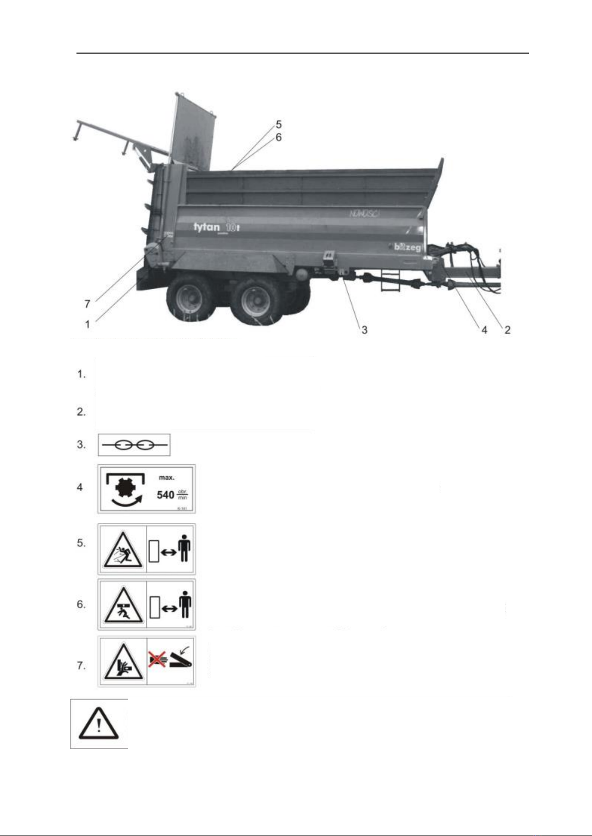
This Operating Manual describes manure spreaders with the following symbols:
Tytan 11 premium, Tytan 11 premium td, Tytan 13 premium td, Tytan 18 premium td. Tytan 11
“premium” spreaders are machines traveling on a single axis, while Tytan 11, 13 and 18
spreaders - “premium td” series - travel on an amortized tandem system. A working part of the
machines mentioned above is an adapter utilized for spreading organic material.
The spreader can be equipped with three types of the adapter. A vertical four-roll adapter, a
vertical two-roll adapter, and a horizontal-disc adapter. The spreader is first of all intended for
even spreading of manure, peat and compost. What is more, is can be used as a trailer with
automatic unloading for crops and other materials transportation, both within a holding and on
public roads. The spreader can work together with tractors that are equipped with an upper or
lower catch for single-axis trailers. Manufacturer’s guarantee conditions for fault-free operation of
the machinery, and information about units that carry out guarantee repairs are provided in the
guarantee card attached to a new spreader. Principles of providing users with spare parts are
described in the Spare parts catalog.
2. Equipment.
When purchasing the spreader check for completeness of the equipment,
including:
1. Operating manual
2. Guarantee card
3. Power take-off shaft
3. Intended use
The manure spreader is a universal multi-functional agricultural machine, which can
be used for the following works, e.g.:
a) spreading of manure, peat or compost, with fertilization doses
reaching 6-60 tons per hectare, depending on the kind and
quality of soil and type of cultivated plants (fig. 1).
b) transportation of crops and agricultural products (potatoes,
beetroot, seeds, cereals, etc.) with a possibility of automatic
unloading with a floor conveyor.

Operating Manual
TYTAN premium
- page 8 -
4. Technical specification.
Technical data of the Tytan premium spreader:
No.
Size
TYTAN 11
TYTAN 11
„td”
TYTAN 13
„td”
TYTAN 18
„td”
1.
Kerb weight [kg]
4550
4600
5245
5320
2.
Rated carrying capacity [t]
9
10
14
2.1
Carrying capacity in the field [t]
12
13
16
3.
Total length [m]
6.8
4.
Total width [m]
2.5
2.65
2.65
5.
Total height [m]
2.76
2.76
2.85
2.95
6.
Distance of the upper side
edge of the box from the
ground
2.39
2.40
2.65
2.95
7.
Length of the load-carrying
body
4.35 m
8.
Width of the load-carrying
body
2.00 m
9.
Height of walls of the
load-carrying body [m]
1.00
1.00
1.25
1.50
10.
Surface area of the load-
carrying body‘s floor
8.75 m2
11.
Load-carrying capacity [m3]
10
10
11
13.5
12.
Clearance from the ground [m]
0.34
0.315
0.45
0.45
13.
Wheel track [m]
1.90
1.90
14.
Number of land wheels [pc.]
2
4
15.
Dimensions of land
wheels’ tires
550/60x
22.5
400/60x
22.5
500/60x22.5
550/60x22.5
16.
Number of axles
1
amortized
2 amortized
17.
Air pressure in the
tires
3.25 bar
18.
Delivery of the tractor’s hydr.
pump
at least 45 l/m
19.
Maximum transportation speed
6.9 m
25 km/h
20.
Working speed
1.1 –2.2 m/s
4 –8 km/h
21.
Pressure on the catch [t]
1.6
1.2
1.6
1.8
22.
Tractor class, min. [KM]
100÷110
110÷120
130÷150

Operating Manual
TYTAN premium
- page 9 -
A -
A
5. Structure and
operation.
5.1 Power transmission system (Fig. 3.1)
Fig. 3.1 Power transmission system scheme.
1 - jointed-telescopic shaft; 2 - front bearing sleeve;
3 - jointed shaft; 4 - internal housing; 5 - jointed shaft;
6 - internal housing II; 7 - shaft with a coupling; 8 - vertical adapter.
5.2. Floor conveyor.
The floor conveyor is composed of closed chains connected via strikes, constructed from a hot-rolled
channel bar (Fig. 4).
The conveyor is driven by a hydraulic engine and a hydraulic transmission installed on the spreader’s
right side. The feed rate (dose) is adjusted in a stepless way, witha oil flow regulator, whichis located
above the spreader’s drawbar. The conveyor can feed forwards and backwards.
The conveyor is tensed with pressure springs, which at the same time play an amortization role, and
which must be pressed properly. Detailed information about the stretcher are described in point
6.4.3.
1 23
Fig. 4
Floor conveyor - a fragment of a chain with a striker.
1 - conveyor’s chain link, 2 - cover plate of a striker, 3 - a striker
7

Operating Manual
TYTAN premium
- page 10
-
Mechanism adjusting tension of the chains, individually for each chain, are located in the
front part of the load-carrying body.
When the conveyor feeds forwards (towards the tractor), you must be
careful so the moved material does not damage or push the front wall of
the load-carrying body.
The floor conveyor can be controlled only during its operation.
5.3. Braking system.
The manure spreader is equipped with a braking system, including:
-service brake - of a pneumatic type, controlled from the tractor’s driver cab
-parking brake - hand, started with a crank located at the front part of the trailer Distribution
of particular elements of the braking system is presented in Fig. 5 scheme.
Fig. 5
Braking system (scheme)
1 –air tank; 2 –brake control valve; 3 –pneumatic cylinder; 4 –B2
connector (for connection with the tractor’s pneumatic installation) ;
4a –connectors of the dual-line installation; 5 –air duct;
6 –handbrake crank; 7 –handbrake cable.
8 –air filter; 9 –braking power adjuster; 10 –spiral hose

Operating Manual
TYTAN premium
- page 11 -
The service brake, with rated load on the trailer, according to the Highway Code regulations, allows
to reach a delay in braking of at least 2.5 m/s2, with braking distance below 10 m. The auxiliary
parking brake holds the spreader uncoupled from the tractor on a surface inclined at up to 16%
(elevation or drop). Structure of the braking system ensures automatic activation of brakes of both
wheels in case of unexpected uncoupling of pneumatic installations of the trailer and tractor.
5.4. Hydraulic installation.
The hydraulic installation is coupled to the tractor with AGRIC push-in fittings. There are two
options of coupling, depending on how manypairs of hydraulic sockets the tractor is equipped with.
In a standard version there are two pairs of fittings, and in the second versions there is a possibility
to install a hydraulic divider to control particular hydraulic devices via a single pair of fittings.
Fig. 13
Hydraulic installation scheme
1 –plug valve; 2 –flow adjuster; 3 –hydraulic motor;
4 –rear cover cylinder; 5 –gear of the floor conveyor; 6 –floor conveyor; 7
–throttle valve of the rear cover;
5.5. Electrical installation and lighting system.
Electrical installation of the spreader’s trailer (Fig. 6) can be powered from a 12VDC source.
The trailer’s lighting system includes all elements of lighting and signalization (Fig. 7)
provided for in the Highway Code for transportation trailers.
Terminals symbols:
31 –chassis ground; 54 –brake light; 58R –navigation
light L –left traffic indicator; R –right traffic indicator;

Operating Manual
TYTAN premium
- page 12 -
31
58R
54
58R 31 54
58L
54 +
58R
54
58R
1
2
3
3
2
1.
Fig. 6
Electric installation scheme
1 –Traffic indicator light (light bulb 21W); 2 –Navigation light (light bulb 5W);
3 –Brake light (light bulb 21W); 4 –Front navigation light (light bulb 10W); 5 –
connector joint; 6 –Plug-in connector socket 5N;
Fig. 7
Lighting system (scheme).
1 –connector cable; 2 –Plug-in connector socket; 3 –front navigation lamp; 4
–front assembly lamp; 4a –traffic indicator light; 4b –rear navigation light;
4c –“STOP” light; 5 – retro-reflecting “triangular” device (red); 6 –retro-
reflecting device (orange), 7 –group of wires,

Operating Manual
TYTAN premium
- page 13 -
6. Machinery utilization and adjustment for work.
6.1. Machinery preparation and adjustment for work
The spreader is sent from the facility completely assembled, adjusted for manure spreading. While
preparing the spreader for work, you need to couple it to the tractor.
For that purpose, you need to place the drawbar at the tractor’s catch level (a catch for single-axis
trailers) using an adjustable support screwed to the front part of the frame. When the spreader is
coupled and the tractor’s catch is locked, you need to rotate the crank 4, which moves the movable
part of the support upwards or downwards, until you feel resistance. If the obtained clearance is
too small, you can free the flange 3 through removingthe pin 5, and place it in an intended transport
position.
While uncoupling the machine when the work is done, the actions related to adjustment of the
support must be repeated in a reversed order.
Fig. 8
Drawback
support
1 –Permanent pipe, 2 –Movable pipe, 3 –Flange, 4 –Adjustment crank, 5 –Pin;
6.2. Coupling the machinery to a tractor
The spreader can be coupled to a tractor only via the catch for single-axis trailers (Fig. 9). Coupling
via a different catch is dangerous for road traffic safety.

Operating Manual
TYTAN premium
- page 14 -
Fig. 9
Coupling the spreader to a tractor.
On a catch to single-axis trailers (hitch)
1 –spreader’s drawbar; 2 – catch for single-axis trailers ø50;
3 –drawbar’s catch string; 4 – jointed-telescopic shaft; 5 –shaft’s cover. On a
catch for single-axis trailers (upper catch)
1 –jointed-telescopic shaft; 2 –spreader’s drawbar;
3 –drawbar’s catch string.
4
5

Operating Manual
TYTAN premium
- page 15 -
6.3. Loading and unloading the trailer.
The trailer should be loaded with a crane, loader or conveyor. The load should be
distributed evenly throughout the whole surface of the load-carrying box floor. Loading of the
manure (peat or compost) should be realized from the rear to the front side of the trailer, what
exerts positive influence on quality of later spreading. Loading of other materials with utilization of
the trailer as a transportation mean, should take place in a reverse order, i.e. from the front to the
rear side of the trailer. While transporting loads that exert significant point pressure on the load-
carrying box floor, what should be avoided, you need to lay thick planks on the surface, providing
surface load, and protecting from damaging the floor and chain conveyor.
6.4. Principles of correct use of the machinery.
6.4.1. Adjustment of the manure dose.
During the fertilization process, the machine’s floor conveyor feeds in direction that is
opposite to the direction of travel, from the tractor to the spreading adapter. The conveyor can
feed in the other direction only in special circumstances, i.e. the machine is clogged or there is a
procedure of cleaning the spreading rollers from foreign elements, but not more than 30 cm.
The conveyor feeding direction depends on the hydraulic oil flow direction through the system,
and the feed rate is adjusted in a stepless manner, with a flow rate hand wheel.
There should be no pressure in sockets and plugs of the push-in fittings during
the coupling process. The coupling must be strong and reliable.
When the work is done, disconnect the cables in a reverse order.
6.4.2. Spreading adapter
Safety and reliability of the adapter’s operation depends to a significant extent on foreign
bodies located in the manure (e.g. stones, wood, etc.). Furthermore, strings present in the manure
can wrap the spreading rollers, causing a drop in the adapter efficiency. The entangled strings
must be immediately removed, otherwise a failure can occur. The wrapped string must be removed
with a sharp tool.
The adapter should be installed on the spreader’s frame with a crane. For this purpose, connect
hooks of the sling with the adapter’s catches located in its upper part.
If the spreading adapter is blocked, you must turn the hydraulic drive of the
floor conveyor off.
Bearing in mind significant oil pressure, which is necessary for proper operation
of the machine, the tractor must have a working system of external hydraulics
and a proper oil level.
A4VS and A2VS vertical adapters
The spreader can be equipped with two kinds of horizontal adapters, four-roller A4VS and two-
roller A2VS. The four-roller vertical adapter has spreading drums, inclined at a level of 15°. Two
internal drums have smaller diameter than the external drums, what causes lower rotational
speed of cutting knives located at the circumference, and this better break-up of the manure. The
two-roller vertical adapter has two spreading drums with a large diameter, inclined at the level of
15°.
Bigger diameter causes bigger working width. Worn-off knives can be replaced with new

Operating Manual
TYTAN premium
- page 16 -
ones. The drums are embedded on an intersecting axis gear with flexible clutches, and bearing
mounted from the top in ball bearings. The manure fed by the floor conveyor is received by the
rollers and spread on the field. While working with a vertical or horizontal adapter, the damper must
be taken maximally upwards. Safety and reliability of the vertical adapter’s operation depends to
a significant extent on foreign bodies located in the manure (e.g. stones, wood, etc.). Furthermore,
strings potentially present in the manure can wrap the spreading drums. The entangled strings
must be removed at they can lead to lower quality of manure spreading. The wrapped string must
be removed with a sharp tool. The adapter should be installed on the spreader’s frame with a
crane. For this purpose join the sling hooks with the adapter’s catch, located in its upper part, and
place it on guide pins of the spreader’s frame, and lock the locks coupling the adapter to the
machinery.
The shut-off valve is located on the adapter’s right side. It protects the rear cover of vertical
rollers from unexpected dropping during repairs and removal of foreign bodies, i.e. stones,
strings, etc.
The four-roll adapter is intended mainly for spreading manure.
The two-roll adapter has two discs, 950 mm in diameter each, which support sowing of loose
materials. This adapter can be utilized for manure, peat, chicken manure and lime spreading.
NOTE: Utilization of the two-roller vertical A2VS adapter for sowing of lime,
significantly increases consumption of the adapter’s working elements.
It is recommended to spread lime with a disc adapter.
Vertical disc adapter
The disc adapter is constructed from two discs with blades, three gearboxes with bevel
gears. There is a horizontal adapter - equipped with two horizontal spreading drums - located
above the disc adapter. Its task is to break up larger particles of the material falling on the
spreading discs. Threading of the worms is located symmetrically on the drum in such a manner
that the fertilizer is drawn inside the adapter during the spreading process. It is embedded in a
tight housing, and it rotates counter-clockwise to the direction of the floor conveyor feed. The
lime or fertilizer fed by the floor conveyor is broken up into fine particles by cutting knives, and
thrown on the spreading discs. While working with manure or compost, the rear damper must be
lifted maximally.
While working with lime or other loose material, the damper is opened at the height
of automatic piling of the fertilizer.
This adapter cooperates with a disc adapter, which spreads the falling and fermented
manure (compost), peat, sludge, chicken manure and lime.
Volumetric adapter
The volumetric attachment is constructed from two side walls and a hydraulically lifted flap. If
you want to mount the attachment, you need to demount the damper. Put the plugs of
hydraulic hoses of the attachment into the socket located on the pole at the right side of the
machinery.
Demounting the rear wall / damper
1. Lift the damper maximally upwards with the hydraulic means.
2. Attach the slings of the lifting device in the damper’s catches.
3. Remove the cylinder’s eyes from the damper’s pins.
4. Remove the damper from guides.
5. Lower the cylinders hydraulically to a bottom position

Operating Manual
TYTAN premium
- page 17 -
Dose of the spread manure depends on:
- feeding speed of the floor conveyor, resulting from the hydraulic oil flow rate through the
flow adjuster.
- spreader’s speed of travel on the field;
- volume weight of the applied fertilizer;
- working width;
Indicative values of fertilization in tones per one hectare (t/ha) are provided in the table on pages
23 - 26.
NOTE:
While spreading the manure, the load-carrying box’s damper must be lifted maximally with
hydraulic cylinders. Partial opening of the damper can cause certain resistance during
transportation of manure towards the adapter, causing damage to the conveyor, pushing the
damper out of the guides or damaging the hydraulic cylinders lifting the damper. The damper can
be opened partially while spreading loose materials; the minimum gap should be 400 mm.
While spreading manure, peat or compost use only lower
floor conveyor feeding speeds, in the range between 1 to 10 on the flow adjuster scale. If you
want to increase the dose of spread material, lower the working speed.
Higher speeds (10-12) serve for automatic unloading of the trailer. In order to get
the best spreading parameters (widths and uniformity) rotations on the tractor’s PTO should be
kept at the level of 520 - 550 rpm.
Lower rpm in the spreading procedure causes a significant drop in the machine’s working
parameters.
The ladder fixed at the load-carrying box’s side enables access to the interior in order to control
the filling level or carry out operational and repair activities.
6.4.3. Adjustment of the conveyor chains tension.
While utilizing thespreader, and first of all in the initial period, you must pay special attention
to maintenance of a proper tension of the conveyor chains. Backlash of the chains visible while
raising them perpendicularly to the direction of movement, at the half length of the load-carrying
box, should be as low as possible. Adjustment is realized via stretchers located in the machine’s
front part.
Fig. 11
Mechanism for tensioning chains of the floor conveyor.
If the work range of the stretcher does not allow further tensioning of the chain, you need to remove
a proper number of the chain links. You shorten the chain by cutting off at least two chain links,
multiplying the number in case there is a need to shorten the chain more. Always remove the same
number of links from all chains.

Operating Manual
TYTAN premium
- page 18 -
6.4.4. Adjustment of brakes (Fig. 5)
The brakes are adjusted separately from each of the four wheels of the trailer.
In order to check for backlash and adjust the brakes, you need to:
couple the spreader with a tractor and secure the tractor from rolling down; lift
the wheelset axis with a hoist;
protect the trailer against dropping and release the wheels’ brake;
using the handbrake crank 1, via the strings 2, shift the arms of the brake expander by 1/3 of
maximum movement, two wheels of the trailer should be braked then; carry out an analogical
action for the remaining wheels of the trailer, using a pneumatic cylinder;
if shift of the arms of the brake expander necessary to brake any wheel exceeds 1/3 of the
maximum movement, you need to adjust the brakes by changing mutual position of toothed bars
on brake expanders; in order to do it you need to partially untighten the castellated nuts tightening
the toothed bars;
when the adjustment is completed, press the toothed bars with castellated nuts and secure with
new cotter pins.
NOTE!
If the brakes are adjusted properly, the aggregate (tractor + trailer) with rated load, traveling at a
speed of 20 km/h, should stop at the distance of 10 m from the beginning of braking, while both
wheels should brake evenly. Having traveled the first 100 km, you must check and possibly adjust
the machine’s brake.

Operating Manual
TYTAN premium
- page 19 -
6.4.5. DRIVE THROUGH JOINTED SHAFTS
1.
Mounting and demounting of the jointed shaft can be
carried out only when the motor is turned off and the
key is taken out of the ignition switch!
2.
You must never turn the jointed shaft on if the motor is turned off!
3.
Nobody can be present near the working jointed
shaft!
4.
Take care of attachment and adequate condition of the protection pipe and the jointed
shaft cover!
5.
It’s possible that after turning the motor off, the
aggregate will be working due to force of inertia. You
must not approach the machine in such a situation.
Works on this part can be carried out only after the
drive is immobilized.
This manual suits for next models
2
Table of contents
Popular Spreader manuals by other brands

Trynex International
Trynex International TurfEx TT5000 owner's manual

Sulky
Sulky DX 20 Original instructions

Handler
Handler PT-6 FSS manual

Glasdon
Glasdon ICEMASTER 50 Instruction leaflet

Cub Cadet
Cub Cadet 125 lb Spreader & 10 Gallon Sprayer Operator's manual

The Handy
The Handy THS50 Operator's manual and parts list