Terrco 6200 User manual

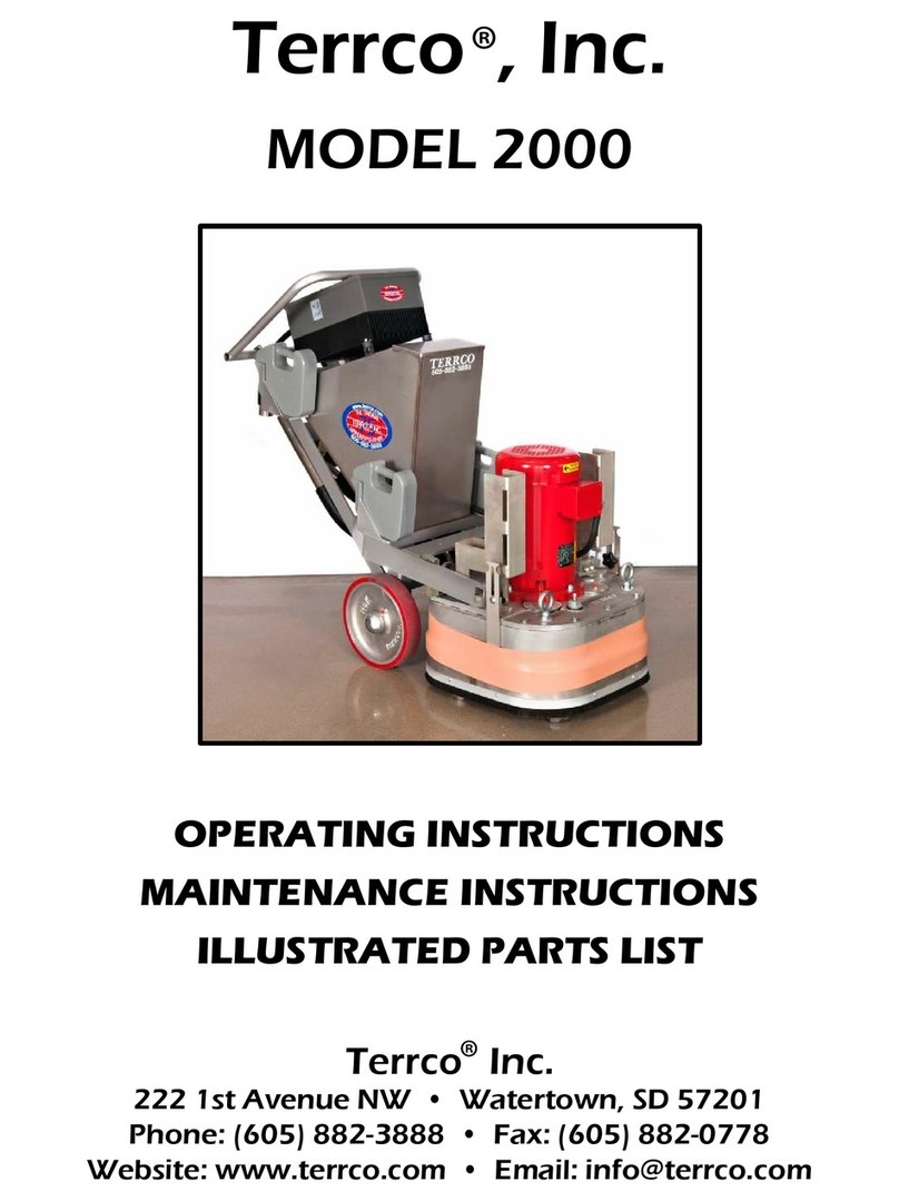
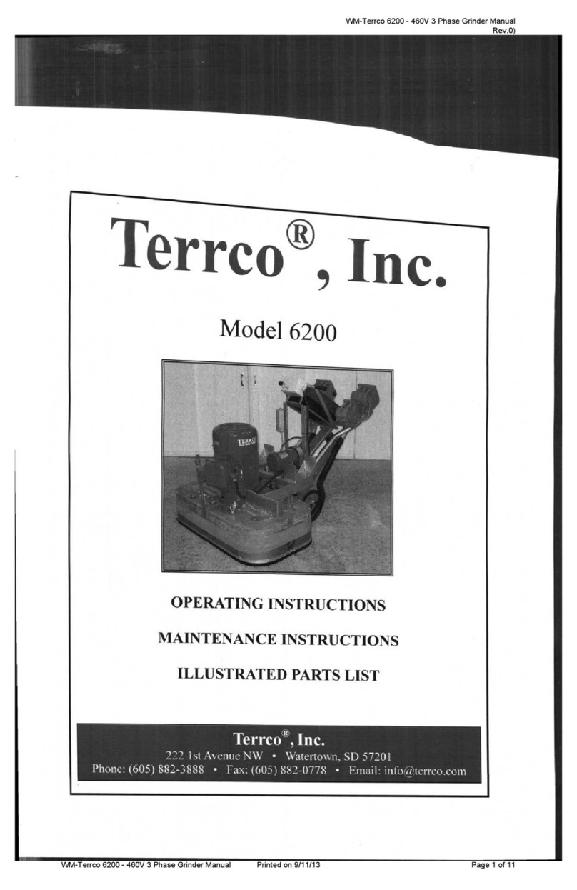
Terrco®, Inc.
Model 6200
OPERATING INSTRUCTIONS
ILLUSTRATED PARTS LIST
MAINTENANCE INSTRUCTIONS
Terrco®, Inc.
222 1st Avenue NW • Watertown, SD 57201
Phone: (605) 882-3888 • Fax: (605) 882-0778 • Email: info@terrco.com

Specifications: Production Rates:
Mastic removal Rate of 1,000 sq. ft. per
hour
Thin-Set removal rates of 1,000 sq. ft.
per hour
Thin-Mil coatings removal of 800 sq. ft.
per hour
Concrete polishing rates of 10,000 sq.
ft. per polishing pad
Terrco® Model 6200
Optimal for jobs exceeding 20,000 sq.
ft.
Despite the weight and size the 6200 is
easily maneuverable
Movable weights for easy one person
operation
Variable Speed Drive
Stainless Steel Guard with four vacuum
ports
Dry Setup
Handle Separates from Gear Case to
Allow Handle and Case to go through
Standard 36" Door
Ten 42 lbs. Pocket Weights to Control
Grinding Pressure
Terrco®, Inc.
222 1ST AVE. NW WATERTOWN, SD 57201
PHONE: (605) 882-3888 FAX: (605) 882-0778
EMAIL: [email protected]m
WEBSITE: www.terrco.com
HP/KW 40/30
Voltage 460
Phase 3
Drive Variable
Amp Draw 46
Breaker (Amps) 60-80
Stone Holder RPM 400-760
Sweep of Discs 53-1/2” (1397 mm)
Abrasive Pressure 1885 lbs (855 kg)
Width of Machine 55” (1397 mm)
Length of Machine 80” (2032 mm)
Height of Machine 54” (1372 mm)
Net Weight 2300 lbs (1043 kg)
Shipping Weight 2565 lbs (1163 kg)
Power Cord (6-4) 100 ft (30,5 m)

SAFTY PRECAUTIONS
-----------------------------------------------------------
This machine is intended for commercial use. It is designed ex-
clusively to grind and polish Terrazzo and concrete floors. Use
only recommended accessories and abrasives.
When the machine is in need of repair, use only Terrco parts.
All operators must read, understand and practice the following
safety precautions.
WARNING: Rotating grinding wheels can cause injury, keep
hands and loose clothing clear.
WARNING: Disconnect power at the machine before servicing
or changing grinding stones.
WARNING: Always check ground (earth) connection prior to
operating machine.
For Safety:
1: Have electrician hook up power to machine.
2: Always operate machine with ground fault protection.
3: Eye, hearing and respiratory protection advised.
4: Service and adjust guards for maximum protection. Never remove the guards.
5: Keep machine clean and properly serviced.


SAFETY PRECAUTIONS WHEN RUNNING
TERRCO GRINDERS
A.Have a qualified electrician hook up correct power
to the machine, grounded properly, with correct
breakers at electrical source.
B.When breaking down machine to change stones or to
check machine always disconnect power to the
machine.
C.Check for wear to ensure no exposed wires.
D.When grinding wet, employees must wear proper
footwear.
E.Always wear appropriate safety protection such as
eyewear, hearing and if needed respiratory
protection.
F.When grinding, watch for problems on the floor such
as bad joints, electrical covers, studs that can cause
injury to operator or machine.
G.Keep machines clean so any potential problems are
visible.
H.When using base machines, use guards for wet or
dry grinding.
I. Also when using base machines, operate with
flexible shaft and housing as parallel to motor as
possible to avoid kinks. Keep flex-shaft greased.

Operating Instructions
INTRODUCTION:
This manual has been prepared to assist you in
the proper operation and maintenance of your
machine. Please bear in mind that your
TERRCO® 6200 is a precision piece of
machinery manufactured to exacting standards.
In order for you to obtain maximum use of your
TERRCO® 6200, we suggest that you read this
manual completely and thoroughly before
attempting to operate your machine. A parts
diagram and parts reference sheet are included
to assist you in ordering the proper parts.
Always give the machine number and model
number when ordering repair parts.
PLELIMINARY PROCEDURES TO FOLLOW BE-
FORE PUTTING THE 6200 IN OPERATION FOR
THE FIRST TIME.
A. Delivery of the Machine
1. On delivery, the contractor should very
carefully examine the shipping crate to see that
no part of the machine is damaged. If damage
is noted, request an inspection immediately and
request a copy of the claim report. When
accepting the machine from the delivering
carrier, note the damage on the Freight Bill
before signing. TERRCO® WILL NOT honor
any claims for broken, damaged, or missing
parts that may have occurred in shipment, as
each machine is checked and inspected for the
same, before leaving our plant.
B. Installation and Replacement of Grinding
Stones
1. Move the counterbalancing weights to the
upper weight baskets.
2. Using the flop handle, tilt machine back
so that the caster wheel rests on the floor.
3. Clean mounting surface both on plug
stone and stone holder. On 2” or 3” diameter
plug stone, push stone in the hole and give the
stone a slight twist to be certain it is securely in
place.
4. Grasp machine handle and lower machine
to the floor slowly so that all stones are resting
on the floor. Make certain no stones have fall-
en or loosened while lowering the machine to
the floor.
C. Transport of Machine
1. With counterbalancing weights in the
upper weight baskets, tilt the machine so that
the caster wheel is firmly on the floor. You can
use the flop handle to pull the machine or you
can fold the flop handle over and push from
gear case side.
D. To operate the 6200
1. Disconnect electrical source.
2. Install stones per instructions in #1B.
3. After stones are installed, lower the
machine until it is in operating position.
CAUTION - Never attempt to start the machine
while lowering machine to the floor, as rear
stones will strike on corners resulting in thrown
stones and possible damage to the machine.
4. Before plugging into the electrical
system, check the voltage at the source. The
minimum acceptable voltage is (210/420 Volt,
60 HZ, 3 phase), or (380 Volt, 50 HZ, 3 Phase).
Anything lower than this can result in blown
heaters and possible motor burnout.
5. If the machine is to operate in an area
more than 100 feet from the source, it will be
necessary to use the next larger size cable (#4-
4) from the source to the 100 feet of #6-4 wire
cable that was furnished with the machine.
6. After you have the cable in place, relieve
pressure on the stones by applying your weight
on the handle and push the start button on the
starter switch, then releasing pressure on the
handle to lower the machine to the floor.
7. We recommend that the first pass over
the floor be made with the weights in the upper
weight baskets. After the floor is “roughed”
out, move the weights to the weight baskets
located on the gear case for maximum abrasive
pressure.
8. Be sure to periodically check stone wear,
to prevent grinding with the steel plugs, rather
than the stones.

General Maintenance for your TERRCO® 6200
A. The Lubrication of the Machine
1. The lubrication of the main gear case
a. The main gear case contains Mobilith AW-1 grease.
b. Gear case grease level must be checked once a year. The level of grease in the gear
case should be up to half the thickness of the helical gears. (Ref. No. 20 on the parts
diagram).
2. The Lubrication of the Wheel Bearings.
a. Use grease gun and grease with 1/2 shot once every six months on each wheel with
Mobilith AW-1 or equivalent.
3. Location of the grease fittings.
a. Eight fittings on bearing caps on top of gear case (Ref. No. 10). Lubricate these
fittings with three shots of Mobilith AW-1 or equivalent every six months.
B. Keeping Machine Clean
1. Daily schedule after each day’s grinding.
a. Tilt machine back on handle.
b. Clean under carriage with water using garden hose and nozzle.
c. Clean all grease fittings.
2. Do not let any cake-up of cement grinding paste occur as this could create an overload on
your machine as well as more weight to push.
C. Replacement of worn, damaged, or missing parts.
1. Advantages
a. If worn parts (bearings, gears, etc.) are not replaced promptly, serious damage to your
machine could occur.
b. Your machine will operate more efficiently with new TERRCO® parts.
2. Use only authorized TERRCO® parts as our warranty will not apply if other than factory
authorized TERRCO® parts are used.
D. Morflex Flexible Couplings
1. Bolts (Ref. No. 34) should be checked weekly for tightness. Loose bolts cause extreme
vibration and premature failure of rubber inserts in the couplings.
2. Your flexible couplings (Ref. No. 41) should be changed a minimum of once a year
whether you use you machine or not.
E. Stone Wear and Replacement.
1. Check your stones for wear periodically, as the stones may be worn flush with stone
holder plugs and the operator may be grinding with the steel stone spiders.


Ref. # Part # Description Qty Ref. # Part # Description Qty
1FE147B 40 H.P., 3 PH, 1770 RPM, 230/460V Motor 151 FEN26 Handle Assembly 1
22142 Capscrew 452 2038 Capscrew 4
32140 Lock Washer 353 1030 Lock Washer 4
4X85 90 Degree Cord Connector 154 2003 Nut 5
52111 Mounting Ring Bolts 455 HB88B Caster 1
6FE-130-6200 Motor Mounting Plate 156 FE72 Water Valve 1
7FE254 Pinion, 30HP Elec Motor, 1.875" 157 2012 Key 8
8FE-114 Motor Key, Electric 158 FE20B Wheel Shaft 2
93011 Machine Screw 32 59 2141 Wheel Bearing Spacer 4
10 T2118 Grease Fitting 45 Degree 860 DS236 Wheel Bearing Seal 4
11 FE-27 Bearing Cap 861 DS235 Wheel Bearing Cone 4
12 2008 Lock Nut 18 62 DS234 Wheel Bearing Cup 4
13 SM-43 Bearing Cone 863 DS5 Wheel Cap 2
14 SM-37 Bearing Cup 16 64 FE189 Valve Stem 2
15 2139 Capscrew 465 FE79 Water Tank Rod 1
16 2099 Capscrew 16 66 LW10 Water Valve Lever 1
17 1022 Lock Washer 30 67 2082 Cotter Pin 1
18 1025 Capscrew 30 68 SM172 Hose Bracket Clamp 1
19 FE252 Gear Case Cover 169 FS39 Clear Water Hose 1
20 FE125B Drive Gear, Electric 270
21 T2130 Capscrew 271 X84 Bracket 4
22 FE4B Driven Gear RH 472 FE263 Inverter Starter-40HP 1
23 SM16 Gear Shaft 873 LW76 Emergency Stop 1
24 SM72 Helical Gear Key 874 FE251 Rubber Mount 4
25 FEN17 Grease Vent Assy 175 FE246 Pocket Weight, Casting, 42 Lb. 10
26 SM15 Driven Gear LH 476 Lower Weight Basket 2
27 FE253 Gear Case 177 2018 Capscrew 1
28 FD40 Dowel Pin 678 FE271 Strap Bracket 2
29 FE259 Stationary Guard 179 SM182 Spring 1
30 FEN9 Splash Guard Lock Nut 380 FD43 Water Guide Bracket 1
31 FE153 Splash Guard Bolt 381 2080 Set Screw 1
32 SM171 Capscrew 32 82 SM186 Handle Spacer Collar 1
33 2027 Washer 32 83 DS7 Wheel 2
34 FE256 Upper Weight Basket 2
35 SM36 Bearing Cone 8
36 SM169 Grease Seal 8 Parts Not Pictured
37 SM89 Driving Spider 8SM424 50 Amp Male Plug 2
38 2148 Washer 4SM 425 50 Amp Connector 2
39 1007 Lock Washer 12 DS134 6-4 Cable, Feet 100
40 1033 Capscrew 12 X86 Straight Cord Connectors 2
41 SM88 Morflex Coupling 8FE266 Vacuum Pipes 2
42 SM192B Stone Spider-Plug 8FE262 Rubber Dust Seal 1
43 2027 Washer 32 FE270 Front Guard Bracket 1
44 SM171 Capscrew 32 LW78 Brush Strip 2
45 FR594 Plug Stone-2" Diameter (Not Included) 24
46 FE260 Movable Splash Guard Assy 1
47 SM57 Handle Grips 2
48 FE256B Lower Weight Basket 2
49 HB-25 Washer 16
50 FE29SS Splash Guard Strap 3
Model 6200 Parts List

MODEL 6200 HANDLE

ITEM NO. PART NUMBER DESCRIPTION QTY.
1 FEN 025 HANDLE BAR - 6200 1
2 FE 307 CONTROL ASSEMBLY 1
3 FE 251 VIBRATION MOUNT 4
4 FE 263 VARIABLE SPEED DRIVE - 40 HP 1
5 LW 076 EMERGENCY STOP 1
6 SM 057 HANDLE GRIP 2
7 SM 457 Y-PIPE RH 1
8 SM 457LH Y-PIPE LH 1
9 HB 088B CASTER 1
10 FE 474 UPPER BELT GUARD 1
11 FE 475 LOWER BELT GUARD 1
12 FE 294 V-BELT 1
13 FE 293 PULLEY 1
14 X-81 STRAIGHT CORD CONNECTOR 3
15 FE 292 2 HP MOTOR 1
16 FE 291 PULL PIN 2
17 FE 285 KEYLESS LOCKING HUB 2
18 FE 280 AXLE DRIVE PLATE 2
19 FE 290 WHEEL BEARING 6
20 FE 267 SELP PROPELLED WHEEL 2
21 FE 287 PILLOW BLOCK 2
22 FE 284 TRANSAXLE 1
23 T3047 HOSE BARB 1
24 FE 289 EXPANSION TANK 1
25 SM 113-SMALL BOX ENCLOSURE 1
T6010 CONTACTOR 1
T6110 OVERLOAD 1
26 X-80 90 DEG CORD CONNECTOR 3
27 SM 091-BUTTON START/STOP BUTTON 1
Other manuals for 6200
2
Table of contents
Other Terrco Floor Machine manuals

