SPE DFG250-1 User manual

DFG250-1
SINGLE SPEED
DIAMOND FLOOR
GRINDER
Operating Manual
This manual is provided to persons purchasing an
SPE machine and may not be reproduced in part or full
without written permission of
SPE International Ltd.
This manual provides the basic information required
and is only to be used as a guideline.
The SPE machines are manufactured and covered by
SPE design registrations granted and pending.
SPE International Ltd reserves the right to alter the
equipment design and specification as required
without notice.
The SPE product range is subject to amendment and
improvement as a result of on going research
Honeyholes Lane, Dunholme, Lincoln LN2 3SU, England
Tel: +44 (0) 1673 860709 Fax: +44 (0) 1673 861119
Email: sales@spe-int.com


DFG250-1
Operating Manual
DFG 250 Single Speed
Diamond Floor Grinder
OPERATING MANUAL
This manual covers to the best of our knowledge the operation and maintenance of the
DFG 250-1 diamond floor grinder. Before operation of the equipment the manual should be
read and understood by the operator. The safety regulations must be followed at all times.
Service of electrical components should be carried out by authorised personnel. Failure to
follow these instructions could result in damage to the machine and/or serious personal injury
or death.
WARNING
Failure to follow these instructions may result in serious personal injury or death. SPE
disclaims all responsibility for damage to persons or objects arising as a consequence of
incorrect handling of the machine and failure to inspect the machine fordamageorotherfaults
that may influence the operation prior to starting work.

DFG250-1
Operating Manual
INDEX
Page No
1 Starting Work
2 Changing Grinding Plate
Wet Grinding
Weight
3 Maintenance
4 Safety
5-6 Accessories
7 Spare Parts Breakdown
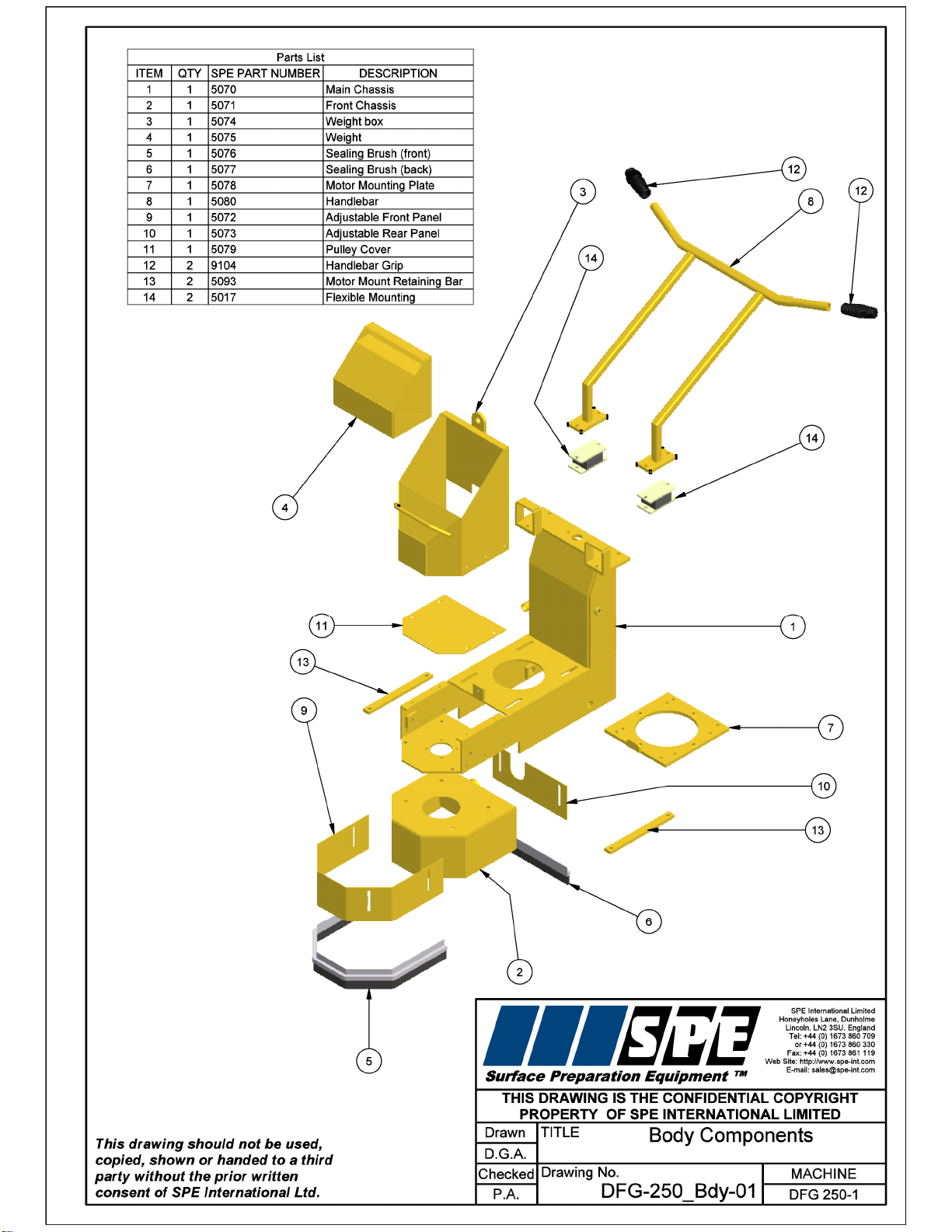
8 Body Components
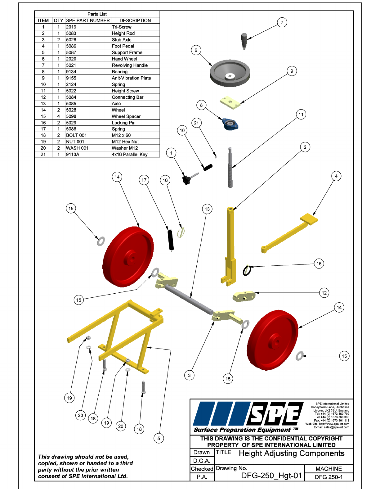
9 Height Adjusting Components
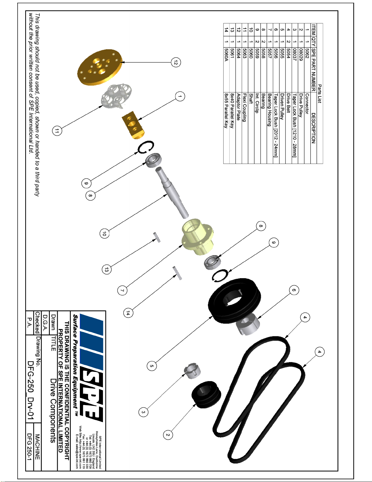
10 Drive Components
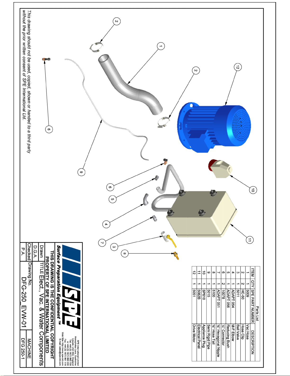
11 Electric, Vacuum & Water Components
12 Main Components Wiring Diagram
13 Electrical Components
14 Specifications
15 Noise/Vibration Assessment
16 Warranty
17 Declaration of Conformity
18 Conditions of Sale

DFG250-1
Operating Manual
STARTING WORK
BEFORE STARTING WORK CHECK SET UP OF THE MACHINE AND GRINDING
PLATE HAS BEEN COMPLETED.
1. Ensure the power supply is correct.
DFG 250 - this should be a 415v 16 amp supply from the mains or generated with a
minimum supply of 10 kva on 50 cycles
2. DFG 250 - the plug on the machine is a 5 pin 415v 16 amp red plug
3. Loosen set screws securing front and rear dust skirt enclosures to allow free movement
up and down.
4. Lower the machine on to the grinding plate by releasing foot pedal.
5. It is vital at this stage that the machine should be set to grind the floor along the same
plane. Incorrect set up will result in uneven diamond wear, deep grinding marks, vibration
and damage to the flexible coupling that support the heads.
6. Set the machine down on the floor to be prepared and check the level of the floor with a
spirit level. Place the spirit level on the front side of the machine and adjust the rear wheel
height using the black hand wheel until the level of the machine is the same as the level of
the floor. Then lock the hand wheel.
7. Set the dust skirts to the correct height approx 0.5mm clear of the floor and tighten up
screws.
8. Lift the floor grinder up using foot pedal ensuring the grinding head is clear of the floor
and fit either a dust extraction hose or a water supply. Examine grinding plate for any
damage and check allen screw bolts are tight. See page 2, Changing grinding plate for
torque setting
The floor grinder is now ready to commence work.
9. Connect the machine to the power supply and turn the red isolator switch to the ON
position. Red light will illuminate on the electric panel. Ensure foot pedal is locked into the
raise position.
10. Start motor up by pressing the green button on electric panel.
11. Lower the machine on to the floor using foot pedal whilst moving the machine either
forwards or backwards. Try to grind in a figure of eight pattern for best finish
NEVER ALLOW THE MACHINE TO REMAIN STATIONARY WHILST THE GRINDING
PLATE IS ROTATING AND IN CONTACT WITH THE SURFACE
12. When lifting machine to cease grinding the head should be lifted off the floor slowly
with the dust extraction still operating in order to allow the dust to clear from the work area
13. If the operator has any difficulty whilst operating the machine press the red stop button
located on electrical panel.
1

DFG250-1
Operating Manual
CHANGING GRINDING PLATE
1. Lift the DFG off the floor to its maximum height using foot pedal.
2. Disconnect from power supply.
3. Tilt the machine backwards on to its handles. The machine must be secured and
supported.
4. Make sure the grinding plate is cool to the touch.
5. Use an Allen key to undo the countersunk screws securing the diamond plate to the
flexible couplings.
6. Remove grinding plate and replace.
7. Ensure grinding plate is seated to coupling correctly prior to tightening counter sunk
screws diagonally to a maximum torque of 75Nm
8. Lower the machine back to an upright position.
9. Reset dust skirt and level machine –See starting work page 1
10. Reconnect to the power supply
CHECK FOR CORRECT WEAR RATE AFTER QUARTER OF AN HOUR AND AGAIN AT
HALF AN HOUR INTERVAL. - THIS WILL GIVE AN IDEA OF WEAR RATE
SEE ACCESSORIES SHEET FOR AVAILABLE PLATES –Pages 5-6
11. Adjust machine level as the plate reduces through wear.
WET GRINDING
When grinding wet a hose is connected to the water tap on the side of the machine where
an adjustment handle for the water supply is mounted. The water is ejected forward under
the grinding plate.
When grinding wet the machine should still not be allowed to stop moving whilst the plates
are in connect with the surface.
WARNING: Do not allow water to make contact with electrical components
WEIGHT
It is recommended that the weight is removed at the commencement of grinding and ONLY
ADDED if an increased pressure is needed on the surface.
2

DFG250-1
Operating Manual
MAINTENANCE
AFTER USE:
- Clean the machine to remove all build up of dust and surface residue. If using a hose
pipe or pressure washer take care that water is not directed onto electrical components and
switches.
(Note: Motors and switches are not waterproof)
- Ensure the height adjustment thread is cleaned and then lightly oiled. Periodically it
should be removed and the female, threaded section cleaned out and oiled regularly to
maintain a light, smooth height adjustment.
- The drive belts will give a long and trouble free operating life if basic procedures are
followed. The drive belts are tensioned by sliding the motor along the adjusting slots. It is
important that the drive belts are not over tensioned. Serious damage could be caused to
the drive shaft, drive shaft bearings and drive motor if the belts are excessively tight.
- All components should be checked daily for tightness and the drive belts for tension.
- The flexible drive couplings that support the grinding heads should be checked on a
weekly basis. The coupling should be firm without excessive movement
-Any excess vibration due to uneven head wear should result in the grinding head being
changed to eliminate damage to couplings and bearing assembly support units.
3

DFG250-1
Operating Manual
SAFETY
Only trained operatives should be allowed to work the DFG250-1 floor grinder.
Note: It is possible that the noise level produced by the Diamond Floor Grinder could
exceed 90dbA. Appropriate PPE must be worn and the equipment must be used in line
with guidelines laid down by the Health & Safety Executive.
Never leave the DFG250 unattended whilst in use. Always stop the motor and lift the
grinding head prior to leaving the machine.
Always ensure that all power leads and hoses are disconnected before attempting to
service the machine. Never tip the machine backwards until the grinding plate has
stopped rotating and the machine has been isolated at main supply.
Noise and vibration will occur at various levels dependant on the attachments and work
being completed. SPE have assessments conducted under test conditions detailed in the
operating manual see page 15. However it is recommended that additional tests are taken
on site to provide the operator with accurate information on using the equipment within the
guidelines laid down by the health and safety executive.
Note:
1) Never operate the DFG250-1 without belt guard fitted.
2) Never operate the DFG250-1 outdoors in wet conditions as the electrical
components are not waterproof.
4

DFG250-1
Operating Manual
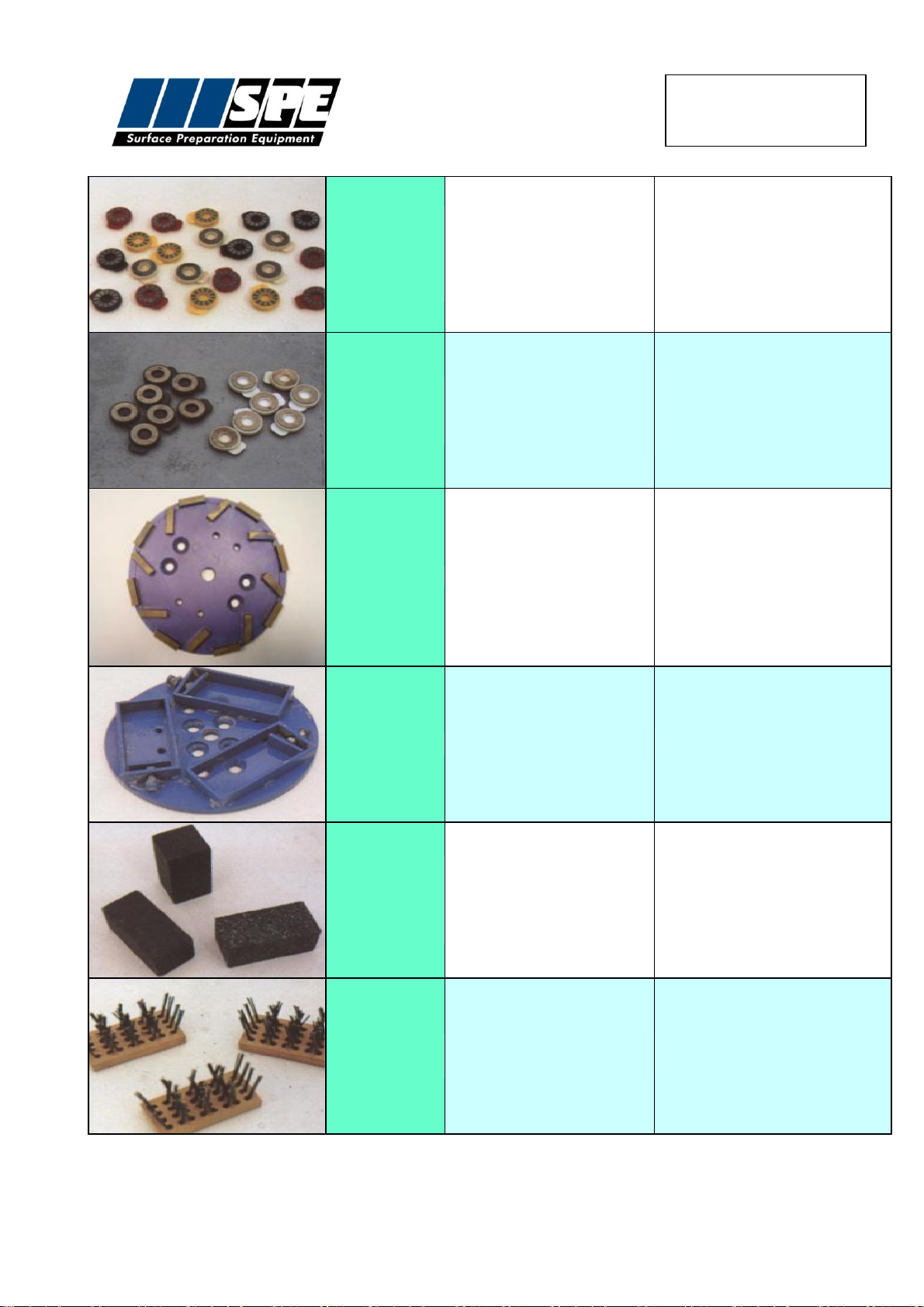
ACCESSORIES
Part No
Description
Application
6401
Economy grade 250mm
10 segment (blue)
Economical removal of most types of
adhesives and surface contaminants.
Excellent for using on rougher surfaces as a
first grind. Can be used wet or dry.
6402
Super Agressive 250mm
10 segment (red)
Designed for the removal of S/L and epoxy
coatings in a commercially viable way. Can
be used for the majority of aggressive
grinding applications and will give extended
wear on heads.
Can be used wet or dry.
6403
Standard Grade 250mm
16 segment (blue)
Removal and grinding of most types of
concrete floor in preparing for follow on
coatings. General all purpose head for most
grinding works.
Can be used wet or day.
6404
High performance 250mm
20 segment (blue)
Fast removal and grinding of most types of
plain and painted concrete floors. Will key
floors for coatings, removal of high spots, lip
edges etc. Suitable for first and second
stage grinding to terrazzo and aggregated
seamless floors.
Can be used wet or dry.
6405
Button head 250mm
16 segment (blue)
For the removal of the thicker adhesive on
sand / cement screed whether open or
closed. Will cope with large volume areas in
a cost effective manner. To be used with
softer elastomeric and thin film coatings.
6408
Polymer diamond backing plate
Backing drive plate for the polymer diamond
system.
Takes 16 polymer button inserts.
5
DFG250-1
Operating Manual
6420
6409
6410
6411
6412
6413
6414
GREEN ULTRA COARSE 16no
BLACK EXTRA COARSE 16no
BROWN COARSE 16no
RED MEDIUM 16no
YELLOW FINE 16no
WHITE EXTRA FINE 16no
BLUE ULTRA FINE 16no
Polymer diamond system to be used only on
the DFG 500 twin speed (slow speed option)
for second stage grinding and polishing of
terrazzo, stone and marble etc. The buttons
fit securely into the aluminium backing plate.
Wet use only.
6422
6423
COARSE STEEL POLYMER
16No
MEDIUM STEEL POLYMER
16No
Steel polymer diamond system to be used
on DFG 500 twin speed (slow speed option).
For second stage grinding and finishing of
cementitious, polyurethane and epoxy
based terrazzo, terrazzo tiles and concrete
flooring. Provides rapid action and long life.
Wet use only.
6403C
Fine grit 250mm 16 segment (purple)
Finishing and polishing of cementitious
polyurathane, epoxy based terrazzo,
terrazzo tiles and decorative aggregated
concrete flooring.
Can be used wet or dry.
6415
Carborundum grinding and wire brush
block holder drive plate.
Drive plate for the carborundum grinding
blocks and wire brush blocks.
6416
6417
6418
Carborundum grinding blocks
Fine
Medium
Coarse
For economical polishing and grinding
removal of high spots, over watered slabs,
rain damaged slabs, lip edges etc.
6419
6421
16 gauge round wire block
Spring steel block
General scarifying, removal of rubber carpet
backing, grease and oil build-up without
damage to substrate.
6

DFG250-1
Operating Manual
7

DFG250-1
Operating Manual
DFG250 SINGLE SPEED
ELECTRICAL COMPONENTS
QTY
DESCRIPTION
SPE PART NO.
1
Panel
SP58015
1
Back Plate
SP55815
1
Contactor
SPLC1D18N7
1
Start Switch
SPZB4BZ101
1
Stop Switch
SPZB4BZ102
1
Start Button
SPZB4BA3
1
Stop Button
SPZB4BS44
1
Panel Lamp
SPZB4BV5
1
Lens
SPZB4BV04
1
Overload
SPLRD16
1
Trip
SP60HD316
1
Gland
9258/200
1
Brass Bush inc. Nut
608-222
4
Rubber Mount
9245/250
1
Isolator 40Amp
SPFWA4/3C
1
16A 5Pin Surface Mtd Plug
SP610
13
DFG250-1
Operating Manual
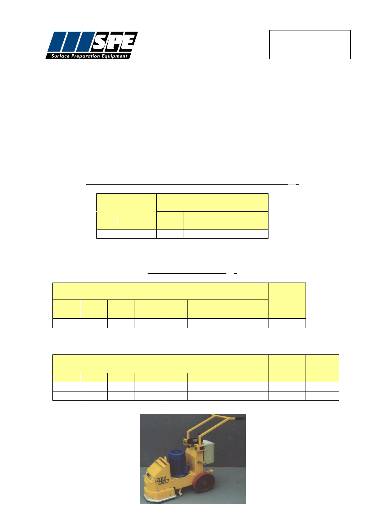
SPECIFICATION SHEET
ELECTRICAL REQUIREMENTS
Machine
Volts
Plug size
Cable Size
(mm)
Max Cable
Length
Transformer
Generator
DFG250-1
380/415
16 Amp 5 Pin
2.5 –4 core
75 metres
-
10 kva
Type
DFG250 Electric
Part Number
DFG250-1
Power Output
5.5 kw
Voltage
380/415
Cycles
50hz
Head Speed r.p.m.
1400
Motor Speed r.p.m.
2800
Machine Dimensions (mm)
Length
Width
Height
Weight (kg)
1120
670
1040
160
Ballast Weight (kg)
1x20
14
DFG250-1
Operating Manual
RECORD OF NOISE AND VIBRATION ASSESSMENT
Manufacturer:
SPE
Type:
Diamond Floor Grinder
Model No.
DFG250-1 Electric
Operation :
Concrete floor surface
Inserted Tool:
1 Diamond plate
Running Conditions:
1400 rpm
HAV Note:
Acoustic Associates
HAND-ARM VIBRATION
Frequency Weighted Energy Equivalent Accelerations (ah,w)
Measurement
Position
Acceleration (m/s2)
X
axis
Y
axis
Z
axis
Vecto
r Sum
Handle
2.29
3.54
2.37
4.84
NOISE LEVELS
Sound Power Level (LWA)
LWA at Octave Band Centre Frequency (Hz)
Sound
Power
Level
LWA
63
125
250
500
1000
2000
4000
8000
51.1
73.7
88.3
92.0
95.1
97.3
90.9
80.3
100.9
Operator's Ear
LAeq,T at Octave Band Centre Frequency (Hz)
Overall
Level
(LAeq,T)
LPeak
dB(C)
63
125
250
500
1000
2000
4000
8000
39.1
57.7
74.6
79.2
81
79.8
75.8
67.2
86.1
101.7
15
DFG250-1
Operating Manual
WARRANTY
The standard warranty period of this equipment is 12 months from the date below in
accordance with the company Conditions of Sale (copy attached).
Warranty start date:
As despatch date
Model:
DFG250-1
Serial no:
Customer name:
Customer Address:
Manufacturer:
SPE International Ltd
Honeyholes Lane
Dunholme
Lincoln
LN2 3SU
England
telephone:
+44 (0) 1673 860709
fax:
+44 (0) 1673 861119
Email:
sales@spe-int.com
Web site:
www.spe-int.com
Distributor:
16
Table of contents
Other SPE Floor Machine manuals


Popular Floor Machine manuals by other brands


NSS
NSS Predator CXC Information & operating instructions

Advance acoustic
Advance acoustic Proterra Instructions for use

Clarke
Clarke MA30 13 B 9087383020 Instructions for use

SapphireScientific
SapphireScientific SS-P 150 User instructions

Priority Manufacturing
Priority Manufacturing Pathfinder PF1500H Operator and parts manual

Nilfisk-Advance
Nilfisk-Advance B1500DC Instructions for use


