Bartell Innovatech Terminator Infinity 2.0 User manual

OIPB-I01029-Infinity2.0_v1.2
INNOVATECH PRODUCTS & EQUIPMENT. 4701 Allmond Ave, Louisville, KY 40209, USA
Telephone: 1-425-405-9100
RIDE-ON TERMINATORS
Terminator Infinity 2.0
COMPLETE MANUAL

P a g e | 2
OIPB-I01029-Infinity2.0_v1.2
Bartell Morrison Inc.
375 Annagem Boulevard
Mississauga, Ontario, Canada
L5T 3A7
Tel: (647) 953-4100
Fax: (647) 953-4101
Bartell Morrison USA LLC
200 Commerce Drive, Unit A
Freehold, NJ, USA
07728
Tel: (848) 225-8100
Fax: (848) 225-8101
SPE International Ltd
Honeyholes Lane
Dunholme, Lincoln, England
LN2 3SU
Tel: 01673 860709
Fax: 01673 861119
Innovatech
4701 Allmond Ave
Louisville, Kentucky, USA
40209
Tel: (425) 405-9100
Fax: (425) 405-9101
ORIGINAL LANGUAGE OPERATING MANUAL FOR
BARTELL RIDE-ON TERMINATORS
© 2017 Bartell Morrison Inc.
No part of this work may be reproduced or transmitted in any form or by any means,
electronic or mechanical, including photocopying and recording, or by any information
storage or retrieval system without the prior written permission of Bartell Morrison Inc.
unless such copying is permitted by federal copyright laws.
Address inquiries or reference permissions care of: Bartell Morrison Inc., 375 Annagem
Blvd., Mississauga, Ontario, Canada L5T 3A7
REV.
DATE
DESCRIPTION
APPROVED BY:
-
01/29/18
Initial release; applies to machines with S/N: INF2-XXXX
1
04/09/18
Updated fasteners
1.2
07/17/18
Updated Images, revised balloon numbering

P a g e | 3
OIPB-I01029-Infinity2.0_v1.2
SAFETY PRECAUTIONS
DANGER
EXPLOSION HAZARD
Never operate the machine in an explosive
atmosphere, near combustible materials, or
where ventilation does not clear exhaust fumes.
WARNING
BURN HAZARD
Never come into contact with the engine or
muffler when engine is operating or shortly after it
is turned off. Serious burns may occur.
WARNING
ROTATING HAZARD
Never place hands or feet inside safety guard
rings. Serious injury will result from contact with
rotating blades.
CAUTION
MOVING PARTS
Before starting the machine, ensure that all
guards and safety devices are in place and
functioning properly.
ATTENTION
READ OWNER’S MANUAL
Read and understand owner’s manual before
using this machine. Failure to follow operating
instructions could result in serious injury or death.

P a g e | 4
OIPB-I01029-Infinity2.0_v1.2
TABLE OF CONTENTS
1. INTRODUCTION 6
2. ABOUT THIS MANUAL 6
3. IMPORTANT SAFETY INSTRUCTIONS 7
o
1.
SAFETY INSTRUCTIONS FOR ALL TOOLS 7
o
2.
ADDITIONAL SAFETY RULES FOR RIDING FLOOR SCRAPERS 8
4. GENERAL OPERATING INSTRUCTIONS FOR THE TERMINATOR®9
5. SAFETY FEATURES 9
o1. AUTO STOP 9
o2. EMERGENCY STOP BUTTON 9
o3. SAFETY INSTRUCTIONS 9
6. TERMINATOR®INFINITY SPECIFICATIONS 10
o1. TOOLS AND SUPPLIES 10
7. VENTILATION REQUIREMENTS 10
8. GUARDS, WARNING NOTICES & SIGNS 10
9. SERVICE INSTRUCTIONS & PERSONNEL 11
10. REPLACEMENT PARTS & MATERIALS 11
11. UNCRATING AND PREPARING THE TERMINATOR®FOR OPERATION 11
o1. TO REMOVE THE TERMINATOR®FROM A CRATE WITH A FORKLIFT: 12
o2. TO REMOVE THE TERMINATOR®FROM A CRATE WITHOUT A FORKLIFT: 12
12. LOADING/UNLOADING PROCEDURES 12
13. OPERATOR CONTROLS 12
o1. DRIVE/JAW CONTROLS 12
o2. AUTO STOP 13
o3. EMERGENCY BRAKE 13
14. DISPLAY & INDICATORS 13
o1. BATTERY/HOUR METER 13
o2. EMERGENCY STOP 13
15. ELECTRIC MOTOR & BATTERIES 13
16. BLADE ASSEMBLY 13
17. TAKING UP FLOOR COVERINGS 14
18. TRICYCLE OR CASTER WHEELBASE AND TIRES 14
19. BATTERY SAFETY 14
o1. RECEIVING THE TERMINATOR®14

P a g e | 5
OIPB-I01029-Infinity2.0_v1.2
o2. LIFTING BATTERIES 14
o3. WEAR PROTECTIVE CLOTHING 15
o4. IC1200 SAFETY 15
20. SETTING UP A CHARGING AREA 15
o1. CONNECTING/DISCONNECTING CHARGER 15
o2. BASIC CHARGING FACTS 15
21. IC1200 CHARGER INFO 16
o1. LEFT DISPLAY 16
o2. RIGHT DISPLAY 16
22. MAINTENANCE PROCEDURES 16
23. PARTS LIST 17
24. WARRANTY 39

P a g e | 6
OIPB-I01029-Infinity2.0_v1.2
1. Introduction
The Terminator®Carpet and Tile Removal Machine is intended for use on large demolition
and asbestos abatement projects as well as smaller floor covering removal jobs. Designed
and built by experienced floor covering demolition and installation experts, the machine
incorporates several design features that are essential for efficient operation:
•Tricycle wheelbase and short turning radius allows for better turning ability - especially
in narrow spaces.
•Jaw position and tool position adjustments allow for changing the angle of the blade for
any application.
•Weight package options in the front and rear provide extra traction needed for tile and
glue removal.
•Built-in forklift transportation slots allow for easy loading and unloading at job sites.
If operated and cared for as instructed in this Manual, the Terminator®provides trouble-
free, safe, and efficient performance.
2. About This Manual
This Manual contains the information and procedures to assist you to operate and maintain
the Terminator®machine safely and correctly. Read this Manual before you operate or
service the equipment. If you need additional information or assistance, please get in touch
with our Customer Service Department:
Innovatech Products & Equipment Co.
4701 Allmond Ave
Louisville, KY 40209
(425) 402-1881 or 800-267-6682
Fax (425) 402-8547
NOTE: Throughout this Manual directional instructions (left, right, up, down, push, pull, etc.)
are given from the point of view of the operator performing the action.

P a g e | 7
OIPB-I01029-Infinity2.0_v1.2
3. Important Safety Instructions
WARNING: When using electric tools, basic safety precautions should always be
followed to reduce the risk of fire, electric shock, and personal injury, including the
following: READ ALL INSTRUCTIONS
1.
Safety Instructions for All Tools
• KEEP GUARDS IN PLACE and in working order.
• REMOVE ADJUSTING TOOLS AND WRENCHES. Form habit of checking to see that
keys and adjusting wrenches are removed from the Terminator®before turning tool on.
• KEEP WORK AREA CLEAN. Cluttered areas invite accidents.
•KEEP CHILDREN AWAY. All visitors should be kept a safe distance from the work area.
• WEAR PROPPER APPAREL. No loose clothing, gloves, neckties, rings, bracelets or
other jewelry to get caught in moving parts. Non-slip footwear is recommended. Wear
protective hair covering to contain long hair.
• ALWAYS WEAR SAFETY GLASSES. Also use a face or dust mask if operating in a
dusty environment. All users and bystanders must wear eye protection that conforms to
ANSI Z87.1. (CAN/CSA Z94.3)
• MAINTAIN EQUIPMENT WITH CARE. Keep equipment clean for best and safest
performance. Follow instructions for lubrication and changing accessories.
• DISCONNECT BATTERY before servicing.
• REDUCE THE RISK OF UNINTENTIONAL STARTING. Make sure handles are centered.
• USE RECOMMENDED ACCESSORIES. Consult the instruction manual for
recommended accessories.
• NEVER STAND ON TOOL. Serious injury could occur if the machine is tipped or rocked.
• CHECK DAMAGED PARTS. Before further use of the tool, a guard or other part that is
damaged should be carefully checked to determine that it will operate properly and perform
its intended function. Check for alignment of moving parts, binding of moving parts,
breakage of parts, mounting and any other conditions that may affect its operation. A guard
or other part that is damaged should be properly repaired or replaced. Do not use tool if
switch does not turn it on and off.
• NEVER LEAVE EQUIPMENT RUNNING UNATTENDED. TURN POWER OFF. Don’t
leave equipment until it comes to a complete stop.
• DO NOT OPERATE ELECTRIC TOOLS NEAR FLAMABLE LIQUIDS OR GASSES OR
EXPLOSIVE ATMOSPHERES. Motors in these tools may spark and ignite fumes.

P a g e | 8
OIPB-I01029-Infinity2.0_v1.2
2.
Additional Safety Rules for Riding Floor Scrapers
CAUTION: FAILURE TO HEED THESE WARNINGS MAY RESULT IN SERIOUS
PERSONAL INJURY OR DEATH AND SERIOUS DAMAGE TO THE
TERMINATOR®.
The Terminator®is to be operated only by qualified, trained personnel.
DON’T attempt to operate the Terminator®if you are not thoroughly familiar with the
operation of the Terminator®.
DON’T operate the Terminator®unless every guard, warning notice or sign is in place.
DON’T use the Terminator®on roofs or floors not designed to carry the weight of the
machine.
DON’T attempt to operate on anything but the designated voltage.
DON’T wedge anything against the motor fan to hold motor shaft.
DON’T operate equipment without guards in place.
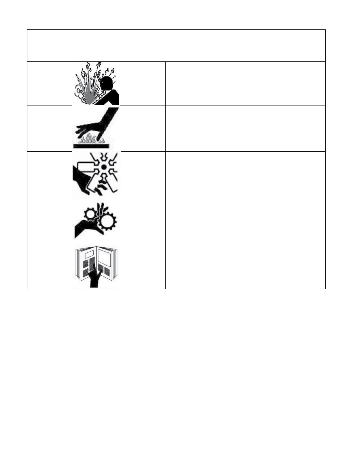
DON’T operate the Terminator®near an open flame or smoking materials
DON’T stand directly behind or in front of the Terminator®when power is enabled.
DON’T lift the hood, inspect the blade, or otherwise service or maintain the Terminator®
while power is enabled.
DON’T operate the Terminator®if the top cover is open.
DON’T overreach. Keep proper footing and balance at all times.
DON’T run the machine into piles of debris, as this may cause the machine to become
unstable and tip over.
DON’T sit on or stand next to, under or around the Terminator®when it is being transported
in a moving vehicle, whether by itself or with other equipment.
DON’T attempt to use the Terminator®on a non-horizontal surface or turn the Terminator®
around on a ramp or hill.
DON’T put your hands or feet in the blade area when the Terminator®is running.
DO turn the power off when not in use.
DO use personal safety equipment such as steel toe shoes, safety glasses, gloves, and ear
plugs.
DO use gloves when changing blades and removal tools. Tools may be hot and cause
burns.
DO familiarize yourself with all safety features and controls before each use.
DO use the Terminator®only for the purpose for which it was designed. Attempting to alter
the Terminator®will invalidate applicable warranties and possibly damage the machine.
DO reduce speed next to walls, machinery and other objects.
DO pre-survey the floor for cracks, ditches, trenches, electrical outlets or bolts, which could
catch the blade of the machine.
DO operate the Terminator®at a safe speed.

P a g e | 9
OIPB-I01029-Infinity2.0_v1.2
4. General Operating Instructions for the Terminator®
The Terminator®is designed to remove carpet, tile and glue residue from floors.
•When removing product, position removed product so it rolls to the side of the machine or
have someone on the side of the machine remove the product. NEVER WALK IN FRONT
OF OR BEHIND THE TERMINATOR®WHILE IT IS RUNNING.
• Sharpen blades or dice material into narrower widths if machine slows down or seems to
be struggling.
•Do not use the Terminator®within one foot of walls or stationary objects. Damage to
objects may occur if the Terminator®strikes them.
•Use safe, OSHA-approved tools and methods for sharpening blades.
5. Safety Features
The Terminator®is equipped with several features to help ensure your safety and the
safety of workers around you.
1. Auto Stop
The Terminator®has two drive levers located to the right and left of the operator seat
and a jaw height lever to the left of the operator seat. The drive levers control the
forward, reverse, left, and right directions of the machine; the jaw height lever raises
and lowers the jaw assembly. You must push (forward) or pull (reverse) and hold the
levers in position to drive the machine or move the jaw assembly in the direction
desired. When you release a lever, the Terminator®or jaw automatically STOPS and
will not move again until you push/pull and hold the levers again. However, these levers
are not meant as brakes. Block wheels with a floor block when stopping on a ramp and
use the emergency brake. Without the emergency brake the machine may roll forward
or backwards on any sloping surface.
2. Emergency Stop Button
To the right side of the operator seat is a red emergency stop button. This will remove
power from the motor and other electronic components. Warning! Removing power
from the Terminator®while on a hill or ramp can lead to a dangerous rollaway situation.
Always engage the parking brake before disconnecting power.
3. Safety Instructions
The Terminator®is designed for safe operation by trained, designated personnel. To
help ensure your safety as a designated operator, read these safety instructions before
you operate the equipment. Regardless of your experience with machinery, the
Terminator®has unique features and systems which you need to know about and
understand before you operate or service the machine.

P a g e | 10
OIPB-I01029-Infinity2.0_v1.2
6. Terminator®Infinity Specifications
1. Tools and Supplies
Maintenance tools and supplies are not provided with the machine. The following are
suggested items to have on the job site.
1. 4” or 7” Grinder
2. 10”-15” Crescent Wrench
3. 16-20 oz. Hammer
4. 3/8” or 1/2” Socket Set
5. Grease Gun
6. WD 40
7. 3/4" Open End and Box Wrench
8. Screw Driver Set
9. Safety Glasses
10. Ear Plugs
7. Ventilation Requirements
Charge the batteries only in well-ventilated areas. (See Battery Safety section)
8. Guards, Warning Notices & Signs
The guards, warning notices and signs are placed on the Terminator®for your protection. If
one of them becomes damaged or is lost, contact our Customer Service Department to
order a replacement.
Element
English
Metric
Length
66”
1676 mm
Width
26.5”
673 mm
Height
47”
1194 mm
Weight
2430 lbs
1105 kg
Tires (OD x W)
15” x 8”
381 mm x 203 mm
Motor Voltage
48 VDC
Motor Power
4 HP
3 kW
Batteries
6 VDC 400 Ah
Motor Operating Speed
0-3000 RPM
Hydraulic Oil Type
ISO 46
Hydraulic Oil Capacity
11 Gal
41.6 L
Hydraulic Relief Valve Pressure
2200 psi
15.17 MPa

P a g e | 11
OIPB-I01029-Infinity2.0_v1.2
9. Service Instructions & Personnel
Like other machinery, the Terminator®requires regular inspection and maintenance of the
batteries, motor, hydraulic system and other parts. To prolong the safe and efficient
operating life of the machine, clean and service it as instructed in the Maintenance section
of this manual.
Always use trained personnel to service the equipment. Never allow anyone to service the
equipment that has not been specifically trained to do so.
If you need help with a service or maintenance problem, contact our Customer Service
Department.
10. Replacement Parts & Materials
The Terminator®is designed and engineered to operate safely and efficiently with the parts
and materials installed on it in our factory. To ensure the continued safe and efficient
operation of the equipment, use replacement parts and materials that meet both of the
following requirements:
•Innovatech must solely authorize replacement parts and materials.
•Replacement parts and materials must be identical to the items originally provided with
the machine, except as authorized by Innovatech.
Never use “equivalent” or substitute parts, except as expressly authorized by Innovatech.
If you fail to adhere to these instructions, you may cause injury to yourself and/or others,
cause damage to the Terminator®, and invalidate applicable warranties.
If you are in doubt about any replacement parts or materials, call our Customer Service
Department for assistance.
11. Uncrating and Preparing the Terminator®for Operation
When you receive the Terminator®, inspect the outside of the crate completely, to detect
damage to the crate itself. If it is damaged, notify the carrier immediately and follow his/her
instructions to file a claim.
Carefully uncrate the machine and inspect it for damage that may have occurred during
shipping. If the shipment is damaged, notify the carrier immediately and file a claim in the
normal manner.
Check packing slip for complete shipment. If shipment is incomplete, notify our Customer
Service Department within 24 hours.
Remove the crate debris, set aside the blades and other packages, and prepare the
Terminator®for operation:

P a g e | 12
OIPB-I01029-Infinity2.0_v1.2
1. To remove the Terminator®from a crate with a forklift:
1. Forklift slots have been provided on the sides of the Terminator®for moving the
terminator with a forklift.
2. To remove the Terminator®from a crate without a forklift:
1. Take 2 x 4’s off the edge of the crate and between the wheels.
2. Place 2 x 4’s behind the crate of the rear of the machine.
3. Make a ramp with the 2 x 4’s and the crate material.
4. To enable power to the Terminator®, turn the key, and twist to release the red knob.
5. Pull back the left and right handles evenly and depress the foot pedal slowly. The
machine will start moving slowly backwards.
6. Ensure that both rear wheels come off the crate evenly. Failure to back off evenly
could result in the machine tipping over and harm to the operator.
7. As the machine moves back, ensure that the center wheel clears the crate. If the
center wheel does not clear the crate, raise the machine until the wheel clears.
8. Once the machine is on the ramp, slide it all the way to the bottom, then raise the
jaw up and set the center wheel down on the ground.
9. Whenever mounting or dismounting the Terminator®, ALWAYS disable the power by
pressing down on the red power knob.
12. Loading/Unloading Procedures
• Do not load or unload the Terminator®on uneven ground.
• Ensure ramps into moving vehicles are stable and square to the ground.
• Always turn off the Terminator®before transporting it.
•Load and unload the machine with a properly weighted forklift or lift-gate.
•Make sure all safety stops are installed on a lift-gate before loading or unloading.
•Never position yourself under/around the machine while moving it with other machinery.
•Park the machine with the jaw completely down after loading.
•Properly secure the machine with chains, tire chocks, and other necessary tie downs.
•Never ride in a moving vehicle next to a Terminator®. It may tip, causing severe injury.
13. Operator Controls
1. Drive/Jaw Controls
The drive and jaw controls (three levers) are located to the left and right of the operator
seat. The drive levers (left and right) control the direction of rotation of the rear wheels.
The jaw height lever (left) controls the vertical position of the jaw assembly.
•Push the left and right levers forward together, slowly at first, to move the machine
forward.
•Pull the left and right levers back together, slowly at first, and hold them in position to
move the machine in reverse.
•Push only the left lever forward to turn the machine to the right.
•Push only the right lever forward to turn the machine to the left.

P a g e | 13
OIPB-I01029-Infinity2.0_v1.2
•To adjust the jaw assembly down, push and hold jaw lever forward. To adjust the jaw
assembly up, pull and hold the jaw lever back.
2. Auto Stop
When you release the drive or jaw lever, the motor continues to run but the drive or jaw
motion automatically stops and will not start again until you push or pull the levers.
3. Emergency Brake
The Terminator®is supplied with an emergency brake to prevent unintended movement
when left unattended. The brake handle is located to the left of the operator seat. Pull
the handle up to engage the brake, push the handle down to release the brake. To
increase tension on the brake you can rotate the end of the handle in a clockwise
direction. Rotate the end of the handle counter clockwise to reduce the tension.
14. Display & Indicators
1. Battery/Hour Meter
The battery/hour meter displays battery life, run-time, and current voltage. At 30%
battery life, the light will turn yellow. At 10% battery life, the light will be red, indicating
very low battery levels and the need to charge. The text display will normally show total
hours to one decimal place, and an alternate mode will display the current voltage to
two decimal places. Please contact your service provider when changing the settings of
your battery/hour meter.
2. Emergency Stop
In case of emergency push down the red emergency button on the right side of the seat
platform to remove power from all electrical components. To restore power, turn the
button to the right and it will return to its original position.
15. Electric Motor & Batteries
The electric motor and batteries are located under the top cover. The electric motor
provides the power to the hydraulic pump to drive the Terminator®. The electric motor
requires little maintenance, inspect wire connections and check for debris to maintain its
efficiency and prolong its operating life.
16. Blade Assembly
Blades are available in different configurations and thickness. An assortment of blades is
included in the purchase price of the Terminator®. Extra blades are available upon request
from Innovatech Products & Equipment Co., Inc.
Installing a Blade:
1. Raise the jaw assembly to maximum up position.
2. Unwrap the pre-sharpened blades and select the blade thickness and length you
need for the job.
3. Loosen the 7 holding bolts.

P a g e | 14
OIPB-I01029-Infinity2.0_v1.2
4. Insert the sharpened blade.
5. Tighten bolts firmly, starting from the center and working out. Bolts should be snug
but not over-tightened.
17. Taking Up Floor Coverings
1. Insert the blade. (See Blade Assembly)
2. Lower the jaw assembly to the floor. Lift the caster wheel off the floor 1/4 inch. Use
previous procedures to drive forward.
3. As the Terminator®is removing flooring material, it is recommended to have another
person at the side of the machine removing accumulating debris.
18. Tricycle or Caster Wheelbase and Tires
The tricycle wheelbase is designed for a better turning ability. The wheel bearings on the
front caster roller require lubrication with grease every 30 hours of machine operation.
There are three fittings, two on the wheel and one on the housing. When running over
debris such as carpet, the carpet yarn will get caught between the wheel and the housing.
Clean out wheel and housing regularly.
The rear tires are solid rubber, tubeless, and require no maintenance. Over time, they may
wear out and need replacing. Before each job, inspect the rear tires and lug bolts. Tighten
the lug bolts as needed to 70 ft.-lbs. torque –it is important to keep the lug bolts tight.
The wheel hubs should be tightened from 310 to 350 ft.-lbs. Inspect and re-torque every 60
hours of operation. Lift the machine off the floor so no weight is on the wheel when re-
torqueing the pack nut.
19. Battery Safety
1. Receiving the Terminator®
After receiving the Terminator®, examine the covers and battery catch tray for signs of
damage. Attention should be given to the crate and pallet of the Terminator®when it
arrives for any damage that may have happened during shipment. If you see any
dented or crushed housing parts contact Innovatech for procedures to repair shipping
damage.
Only trained or authorized personnel should change, repair or charge batteries.
2. Lifting Batteries
Always use proper lifting equipment to reduce the risk of battery damage, shorting and
possible injury. An insulated lifting device used with an overhead hoist is the safest way
to move a battery. Chain hoists used to handle batteries should be equipped with a non-
metallic container or bucket to prevent the chains from dangling and possibly causing a
short by coming in contact with exposed cell connectors on the top of the battery.
Never lift batteries by the inter-cell connecting cables, the connectors will come apart
while the battery is in midair. Connectors on these cables are designed for maximum

P a g e | 15
OIPB-I01029-Infinity2.0_v1.2
current flow, not strength. Connect the lifting device to the negative terminal only if there
is not a lifting strap in place. Lifting by both terminals could cause the negative and
positive terminals to short.
3. Wear Protective Clothing
When working on or near batteries, always wear proper protective clothes including a
face shield, safety glasses, long sleeved shirt, and acid-resistant gloves. Do not wear
any metal jewelry including rings, as they can short circuit a battery and become
extremely hot if it accidentally contacts exposed intercell connectors.
4. IC1200 Safety
The charger may become hot while in use, please use care and hand protection if the
charger must be handled while charging.
20. Setting up a Charging Area
All owners of the Terminator®need to designate a charging area to charge the battery pack
at the end of a workday or while storing the Terminator®, this area should have all the
proper battery handling equipment.
1. Connecting/Disconnecting Charger
Always ensure the Terminator®is not running before connecting the battery charger
leads. The charger sockets are located in the bottom-left corner of the front panel, near
the foot rest.
It is recommended to use the charging cables provided as it is potentially dangerous to
use different gauges or lengths of cable and could reduce charging capacity. If other
extensions cables are to be used, they must be 3-wire cord no longer than 100 ft. (30m)
at 10 AWG or 25 ft. (7.5m) at 16 AWG, per UL guidelines.
When charging both chargers at the same time, ensure they are going to their own
dedicated circuits, as their combined amperage draw can reach 30A.
It is recommended to use both the primary (left inlet) and secondary (right inlet) chargers
for a total of 14 hours to achieve maximum battery capacity.
Live leads can cause arcing and sparks which could cause an explosion if battery gases
are present, please check that the main contactor/disconnector is not in the on condition
when you connect or disconnect the battery terminal plug. In addition, the battery
connector terminals will become pitted over time resulting in poor connections and
increased heat generation in the battery leads and connectors.
2. Basic Charging Facts
•The Terminator®is supplied with two Delta-Q IC1200 chargers.
•When a discharged battery is initially placed on charge, it will draw a current close to
the charger’s maximum output. As the battery voltage rises to its rated voltage the
charger output will automatically adjust to assure a safe and efficient charging rate.
•The IC1200 Charger is designed to start and stop so as not to over charge the
battery pack. The computerized control unit determines when the battery is fully
charged and then automatically ends the charge cycle.

P a g e | 16
OIPB-I01029-Infinity2.0_v1.2
21. IC1200 Charger Info
1. Left display
From the top to the bottom, there are three lights that function as follows:
1) Fault/Error Indicator: Solid Red = Charger fault
Flashing Amber = External error
Flashing Green = USB port active
Solid Green = Safe to remove USB
2) Battery Indicator: Flashing Green (half) = Low state of charge
Solid Green (half) = High state of charge
Flashing Green (full) = High state of charge
Solid Green (full) = Charge completed
3) AC Power Indicator: Solid Blue = AC power available
2. Right display
From the left to the right, there are two lights and one button that function as follows:
1) Charging Output Indicator: If illuminated, the charge output is active and a
potential risk for electrical shock is present.
2) Charge Profile/Error Display: Will display one of four possible codes to indicate
different failure states and aid in troubleshooting.
3) Select Charge Profile: Only needed when changing a charge profile on the
charger. All charger profile changes should be carried out by someone with
knowledge of the charger system.
22. Maintenance Procedures
1. Grease Caster Wheel at three fittings every 30 hours.
2. Check Hydraulic Oil once a month. Change every 18 months with NUTO H 46 or ISO 46
or if fluid is overheated 200°F or higher.
3. Change hydraulic filter every 60 hours.
4. Clean Caster Wheel and Back Tires with wire wheel when necessary.
5. Look for leaks, find and tighten fittings. Do not over-tighten fittings.
6. Check all hoses and clamps once a week.
7. Inspect rear tires and lug bolts. Tighten lug bolts as needed to 70 ft.-lbs. torque.
8. Check wheel hub every 60 hours of operation. Wheel hub pack nut should be torqued
from 310 to 350 ft.-lbs.

P a g e | 17
OIPB-I01029-Infinity2.0_v1.2
23. Parts List
Terminator Infinity 2.0

P a g e | 18
OIPB-I01029-Infinity2.0_v1.2
Front Panels & Seat Breakdown
Item No.
Part Number
Description
Qty.
101
11-0085
Pan Head Phillips Screw, #6-32 x 1/2”
4
102
12-0018-06
Lock Washer, M6
4
103
12-0026
Hex Head Cap Screw, M6-1.0 x 12mm
4
104
12-0043-16
Serrated Flange Cap Screw, M6-1.0 x 16mm
23
105
13-0257
GT50 Seat w/ microswitch
1
106
23-0155
Infinity Flanged Inlet Receptacle
2
107
53-0363
Uni-Frame Assembly
1
108
53-0370
Uni-Frame Front Side Panel
2
109
53-0397
Uni-Frame Seat Mounting Bracket
2
110
53-0418
Infinity Front Panel
1
111
96-0389
Infinity Seat Platform Assembly
1

P a g e | 19
OIPB-I01029-Infinity2.0_v1.2
Front Exterior Breakdown
Item No.
Part Number
Description
Qty.
201
11-0035
Flat Washer, 3/8”
8
202
11-0045
Adjustable Clevis Pin, 5/8” x 3” L
2
203
11-0052
Hitch Pin
8
204
11-0236
Clevis Pin, 1/2” x 3” L
2
205
12-0021-10
Nyloc Nut, M10-1.5
4
206
12-0034-40
Hex Head Cap Screw, M10-1.5 x 40mm
4
207
13-0378
Caster Wheel Replacement
1
208
31-0043
Hydraulic Fitting, 90 deg 4 JIC –8 SAE
2
209
34-0015
Hydraulic Ram (90 deg)
1
210
53-0117
Foot Rest, 1-piece
1
211
96-0386
Pivoting Jaw Assembly
1

P a g e | 20
OIPB-I01029-Infinity2.0_v1.2
Front Interior Breakdown
Item No.
Part Number
Description
Qty.
301
12-0018-06
Lock Washer, M6
2
302
12-0018-08
Lock Washer, M8
8
303
12-0026
Hex Head Cap Screw, M6-1.0 x 12mm
4
304
12-0032-25
Hex Head Cap Screw, M8-1.25 x 25mm
6
305
12-0032-30
Hex Head Cap Screw, M8-1.25 x 30mm
2
306
12-0035-06
Flat Washer, M6
2
307
12-0035-08
Flat Washer, M8
4
308
12-0043-16
Serrated Flange Cap Screw, M6-1.0 x 16mm
6
309
12-0051
Socket Head Cap Screw, M5-0.8 x 16mm
2
310
12-0053
Hex Jam Nut, M10-1.5
5
311
13-0385
Infinity Drive Lever Knob, 1/2"-13, 1 7/8” dia.
2
312
23-0157
Circuit Breaker, 80A 48V
1
313
24-0231
Junction Stud
1
314
35-0059
Infinity Jaw Lever
1
315
53-0427
Infinity Drive Lever
2
316
53-0429
Infinity Charger Bracket
2
317
53-0430
Infinity Charger Mount
1
318
81-0671
Infinity Primary On-board Charger
1
319
96-0384
Infinity Controls Assembly (L)
1
320
96-0385
Infinity Controls Assembly (R)
1
Table of contents
Other Bartell Floor Machine manuals
Popular Floor Machine manuals by other brands

Tennant
Tennant R3 ReadySpace Operator's manual

Superabrasive
Superabrasive Lavina 32 Pro user manual

Amano
Amano Pioneer Eclipse PE420GP Series Operator's manual

Tennant
Tennant S8 Operator and parts manual

Xtreme Polishing Systems
Xtreme Polishing Systems Genie Presto Pro Operator's manual

Nilfisk-Advance
Nilfisk-Advance SR 1700 2WD B user manual

Windsor
Windsor COMPASS CMPS 10070050 operating instructions

Tornado
Tornado ExSELLerate Series Dealer Training Guide

Sandia Plastics
Sandia Plastics Sniper 2-100 Operation and maintenance manual

Trelawny
Trelawny TCG500 operation & maintenance

Onfloor
Onfloor PRO SERIES 16 Safety, operation manual & parts list

Taski
Taski swingo 750E Instructions of use